
In the first project of this chapter, we are going to see a very simple case of M2M communication, where one ESP8266 Wi-Fi chip will send a trigger signal to another chip (via the cloud, of course), that will in response toggle the state of an LED. For the trigger, we'll use a simple push button connected to the first ESP8266.
Let's first assemble the hardware for this project. For the LED board, the hardware configuration is really easy: simply place the resistor in series with the LED, just as we already did in earlier chapters. Then, connect the resistor to pin 5 of the ESP8266, and the other pin to the ground.
This is the final result for the LED board:

For the board that will host the push button, first place the push button on the board, as well as the ESP8266. Then, connect the resistor to one side of the push button, and the other side of the resistor to the ground. Also connect pin 5 of this ESP8266 Wi-Fi chip to this side of the push button. Finally, connect the other side of the push button to the VCC pin of the ESP8266.
This is the final result for the board with the push button:

We are now going to configure both boards so they can communicate with each other. As I said earlier, we are going to use the IFTTT service to make the two boards talk to each other.
We are first going to configure the LED board so it can receive commands from the cloud. For that, we'll use the aREST framework once again:
- This sketch starts by importing the required libraries:
#include <ESP8266WiFi.h>
#include <PubSubClient.h>
#include <aREST.h>
- Next, we create the required clients to connect to the cloud:
WiFiClient espClient;
PubSubClient client(espClient);
- We also initialize the aREST library:
aREST rest = aREST(client);
- Next, we give a unique ID to the device:
char* device_id = "01e47f";
You also need to need to enter your Wi-Fi network credentials here:
const char* ssid = "wifi-name";
const char* password = "wifi-password";
- Next, we define a Boolean variable to hold the current state of the LED:
bool ledState;
We also define a function to toggle the LED, which we will implement later:
int toggle(String command);
- In the
setup()function of the sketch, we expose the toggle function to aREST, and also connect the chip to the Wi-Fi network:void setup(void) { // Start Serial Serial.begin(115200); // Set callback client.setCallback(callback); // Give name and ID to device rest.set_id(device_id); rest.set_name("led"); // Function rest.function("toggle", toggle); // LED state ledState = false; // Connect to WiFi WiFi.begin(ssid, password); while (WiFi.status() != WL_CONNECTED) { delay(500); Serial.print("."); } Serial.println(""); Serial.println("WiFi connected"); // Pin 5 as output pinMode(5, OUTPUT); } - In the
loop()function of the sketch, we simply keep the connection with the aREST cloud platform:void loop() { // Connect to the cloud rest.handle(client); } - At the end, we also need to implement the function to toggle the LED. We simply invert the state of the LED when the function is called, and then we also apply this new state to the LED:
// Toggle LED
int toggle(String command) {

  ledState = !ledState;
  digitalWrite(5, ledState);
  return 1;
}
You can also grab this code from the GitHub repository of the book:
https://github.com/openhomeautomation/iot-esp8266-packt
Then, modify the credentials inside the code, and upload it to the board on which the LED is located.
Now, we are going to see how to configure the board on which the push button is located, which will trigger an event at IFTTT whenever the button is pressed:
- This starts by including the ESP8266 Wi-Fi library:
#include <ESP8266WiFi.h>
- Next, you also need to define your Wi-Fi credentials:
const char* ssid = "wifi-name";
const char* password = "wifi-pass";
- You also need to insert your IFTTT key at this point:
const char* host = "maker.ifttt.com";
const char* eventName = "button_pressed";
const char* key = "ifttt-key";
- In the
setup()function of the sketch, we simply connect the ESP8266 to your Wi-Fi network:void setup() { Serial.begin(115200); delay(10); // We start by connecting to a WiFi network Serial.println(); Serial.println(); Serial.print("Connecting to "); Serial.println(ssid); WiFi.begin(ssid, password); while (WiFi.status() != WL_CONNECTED) { delay(500); Serial.print("."); } Serial.println(""); Serial.println("WiFi connected"); Serial.println("IP address: "); Serial.println(WiFi.localIP()); // Pin 5 as input pinMode(5, INPUT); } - In the
loop()function of the sketch, we check whether the button has been pressed:if (digitalRead(5)) { - If that's the case, we send a message to IFTTT. We first connect to their servers and create a request:
// Use WiFiClient class to create TCP connections WiFiClient client; const int httpPort = 80; if (!client.connect(host, httpPort)) { Serial.println("connection failed"); return; } // We now create a URI for the request String url = "/trigger/"; url += eventName; url += "/with/key/"; url += key; Serial.print("Requesting URL: "); Serial.println(url); - Once that's done, we actually send the request to IFTTT:
client.print(String("GET ") + url + " HTTP/1.1 " + "Host: " + host + " " + "Connection: close "); int timeout = millis() + 5000; while (client.available() == 0) { if (timeout - millis() < 0) { Serial.println(">>> Client Timeout !"); client.stop(); return; } } - To end the request, we read the data coming back from IFTTT and print it:
while(client.available()){ String line = client.readStringUntil(' '); Serial.print(line); } Serial.println(); Serial.println("closing connection"); } - You can now also grab the sketch from the GitHub repository for the book and upload it to the board.
However, for now, our two boards are not communicating with each other. This is why we are now going to go to IFTTT in order to create a recipe to link those two boards.
- On the IFTTT website, create a new recipe and choose the Maker channel as the trigger:

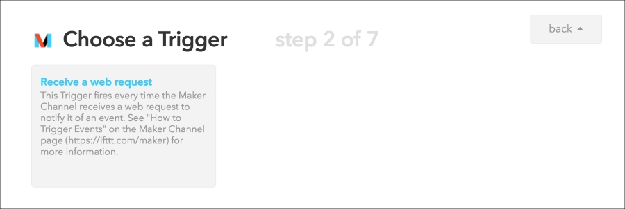
- Next, choose Receive a web request as the trigger type:
- As the event, enter
button_pressed, which is also what we entered inside the Arduino sketch:
- As the action channel, also choose the Maker channel:

- For the action, select Make a web request:

- For the action parameters, we basically need to call the function on the device we created. Therefore, simply enter the parameters just as seen in this screenshot:

- You of course need to modify the URL with the device ID you set inside the code. After that, create the recipe, which should now appear inside your IFTTT account.
- You can now finally test the project, as IFTTT is now making the link between our two boards. Just press on the push button, and should quickly see that the LED will come on. Note that this can take 2-3 seconds, as the information needs to go through the IFTTT servers first. You can also press the button again to switch the LED off. You have now built your first basic M2M communication project!