
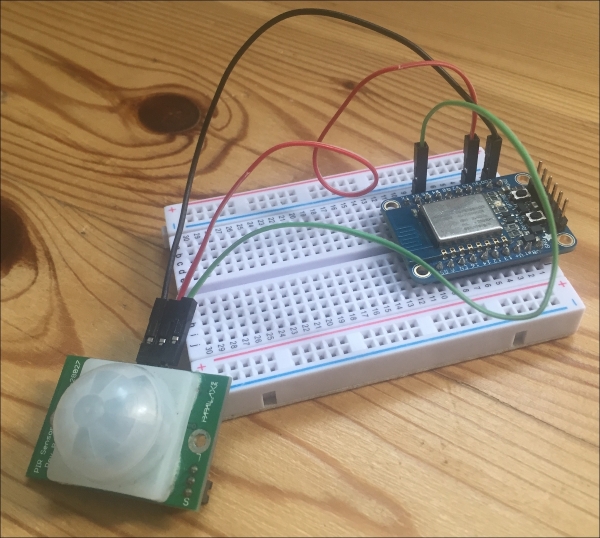
We are now going to assemble the different parts of this project. First, we are going to configure the motion sensor module. For this first module, after placing the ESP8266 board on the breadboard, connect the VCC pin of the sensor to VCC, GND to GND, and finally the OUT pin of the sensor to pin number 5 of the ESP8266.
This is the final result for this module:
Let's now deal with the temperature and humidity module. Place the sensor on the breadboard, and then connect the first pin to VCC, the second pin to pin number 5 of the ESP8266 board, and finally the last pin of the sensor to GND.
This is the final result for this module:

Let's now assemble the LED dimmer module. Here, we are going to use a simple LED as the output, but you can of course use this as the starting point of a module to control more LEDs in your home, or even lamps.
To connect the LED to the ESP8266, simply place the LED in series with the 330 Ohm resistor on the breadboard, the longest pin of the LED in contact with the resistor. Then, connect the other end of the resistor to pin 5 of the ESP8266, and connect the other end of the LED to GND.
This is the final result for this module:
