So, the first recipe of this chapter is about the making of the Armature by hands for our Gidiosaurus.
In this first recipe, we are going to build by hands the basic rig, which is the skeleton made only by the deforming bones.
However, first, let's prepare a bit the file to be worked:
- Start Blender and open the
Gidiosaurus_unwrap_final.blendfile. - Disable the Textured Solid and Backface Culling items in the 3D view Properties sidepanel, join the 3D window with the UV/Image Editor window, and click on the 11th scene layer to have only the Gidiosaurus mesh visible in the viewport.
- Go to the Object window under the Display subpanel and enable the Wire item. This will be useful in the process in order to have an idea of the mesh topology when in Object Mode and Solid viewport shading mode. However, for the moment, press the Z key to go in the Wireframe viewport shading mode.
- Press 1 on the numpad to go in the Front view, and press 5 on the numpad again to switch to the Ortho view.
- Save the file as
Gidiosaurus_rig_from_scratch_start.blend.
Let's start:
- Be sure that the 3D Cursor is at the origin pivot point of the Gidiosaurus mesh. Put the mouse pointer in the 3D view, press Shift + A, and in the Add pop-up menu, select Armature | Single Bone:

Adding the first Armature's bone
- Press Tab to go into Edit Mode and select the whole bone by right-clicking on its central part; move the bone upwards to the Gidiosaurus's hips area (G | Z | Enter or left-click to confirm), and then go in the Side view (3 key on the numpad) and center its position by moving it on the y axis:

Positioning the bone in Edit Mode
- Right-click on the Head of the bone to select it and by pressing G to move it, scale the bone size to fit the pelvis area:

Scaling the bone in Edit Mode
- Go to the Item subpanel under the 3D view Properties sidepanel, or in the Bone window under the main Properties panel to the right-hand side of the screen, and rename Bone (default name) as hips:

Renaming the bone
- Press Z to go in the Solid viewport shading mode, and then go to the Object Data window and enable the X-Ray item under the Display subpanel.
- With the tip of the bone selected (the Head), press the E key to extrude it. By this process, and by following the wire topology visible on the mesh as a guide, go upwards to build the Gidiosaurus spine (2 bones), chest (1 bone), and neck (1 bone); as much as possible, try to place the Heads (the tips/joints) of the bones aligned with the transversal edge-loops on the mesh's articulation:

Extruding the bone to build the spine
- Go again to the Object Data window under the Display subpanel, and enable the Names item (in the following screenshot, all the bones have been selected just to highlight them and their respective names). As you can see in the screenshot, the extruded bones get their names from the previous one, so we have hips, then hips.001, hips.002, and so on:

The bones' names
- Select the hips.001 bone and rename it spine.001; select the hips.002 bone and rename it spine.002.
- Select the hips.003 bone and rename it chest; select the hips.004 bone and rename it neck.
- Select the tip of the neck bone and extrude it; rename the new bone (neck.001) as head:

The renamed bones and the head bone
So, now we have built the spine - neck – head part of the Armature; actually, one thing is still missing: the bone to animate the mandible.
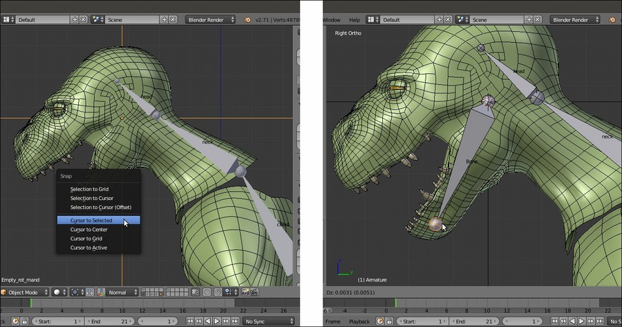
- Press Tab to get out of Edit Mode. In the Side view, enable the 15th scene layer on the 3D viewport toolbar, in order to show the Empty_rot_mand object; select it and press Shift + S to call the Snap pop-up menu. Then, select the Cursor to Selected item.
- Reselect the Armature and go again into Edit Mode. Press Shift + A to add a new bone; move its Head to resize and fit it inside the mandible of the Gidiosaurus:

The mandible's bone
- Rename it mand and in the Bone window under the main Properties panel, in the Relations subpanel, click on the Parent slot to select the head item from the pop-up menu with the bones list. Leave the Connected item unchecked:

The Parent slot and the pop-up menu to select the parent bone
At this point, we can already see some particular setting to be applied to the bones.
- Go to the Object Data window under the Properties panel and in the Display subpanel, switch from the default Octahedral to the B-bone button:

The bones visualized as B-bones
- Press A to select all the bones, and then press Ctrl + Alt + S (or go to the Armature item in the window toolbar, and then go to Transform | Scale Bbone) and scale the B-bones to 0.200 (hold the Ctrl key to constrain the scaling values; the B-bones scaling works both in Edit Mode and Pose Mode).
- Select only the chest bone and scale it bigger to 2.500; select the head bone and scale it to 4.000:

The B-bones scaled for better visualization
- Go to the Object window and under the Display subpanel, click on the Maximum Draw Type slot (set to Textured by default) and switch it to Wire.
- Press Ctrl + Tab to switch the Armature directly from Edit Mode to Pose Mode. Right-click on the chest bone to select it and go to the Bone window under the main Properties panel; in the Deform subpanel, set Segments under the Curved Bones item to 3:

The chest B-bone with 3 curved segments
- Select the spine.002 and spine.001 bones and set Segments to 2. Select the neck bone and set Segments to 3.
- Select the Gidiosaurus mesh, go to the Object window, and disable the Wire item under the Display subpanel:

The rig so far
- Press Ctrl + Tab to go out of the Pose Mode, and then Shift + S | Cursor to Selected to put the 3D Cursor at the rig/mesh/center of the scene pivot point.
- Press Tab to go into Edit Mode and press the 1 key on the numpad to go in the Front view; go to the Object Data window, under the Display subpanel, and switch back from B-bone to Octahedral (even if the visualization mode is different, the bones set as B-Splines still keep their curved properties in Pose Mode).
- Press Shift + A to add a new bone at the cursor position. Move and resize it to put it as the clavicle bone—almost horizontal and slightly backward oriented, on the left-hand side of the rig. Rename it shoulder.L and in the Parent slot under the Relations subpanel, select the chest item:

The shoulder.L bone
- In the Front view, select the Head of the shoulder.L bone and extrude it 3 times to build the bones for arm, forearm, and hand:

Extruding the shoulder.L bone to obtain the skeleton's bones for the arm
- Now, exit Edit Mode and right-click to select the Gidiosaurus mesh; enter Edit Mode, select one or more edge-loops at the elbow level, and press Shift + S | Cursor to Selected.
- Get out of Edit Mode, select the Armature; go into Edit Mode, select the joint between the arm and forearm bones and press Shift + S | Selection to Cursor:

Placing the elbow joint
- This is the easiest way to correctly align the rig joints with the mesh edge-loops. Do the same for the joint of the wrist and the bone of the hand; rename the bones as arm.L, forearm.L, and hand.L:

Fixing the position of the wrist joint and hand's bone
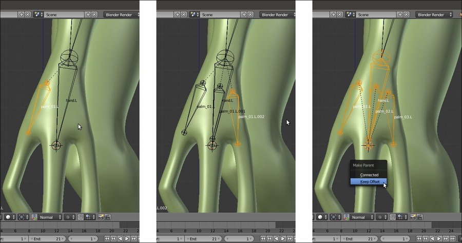
- Select the hand.L bone and use Shift + D to duplicate it; scale it smaller (S | 0.600 | Enter), rename it palm_01.L, and move it above the joining of the palm with the thumb. Use Shift + D to duplicate it 2 more times and move the new bones above the joining of the other two fingers; rename them palm_02.L and palm_03.L.
- Use Shift to select the three palm bones and, as the last one, the hand.L bone; press Ctrl + P | Keep Offset to parent them (not connected) to the latter one:

Adding the palm bones
- Select (individually) the Heads of each palm bones and extrude the bones for the fingers; center their joints with the 3D Cursor/Snap menu method and rename them properly (thumb, index, and middle):

The bones for the fingers
- Again with the 3D Cursor at the rig pivot point, add a new bone and shape it to fit inside the left thigh, the Tail at the top, close to the hips bone, and the Head at the knee location; select it and use Shift to select the hips bone, and then press Ctrl + P | Keep Offset. Extrude the bone's Head three times to build the leg – foot skeleton.
- Extrude also the bones for the toes and repeat the previously described process to center the joints, and then rename all the new bones (leg, calf, foot, toe inn, and ext):

The bones for the leg and toes
In the preceding screenshots, you can see that we have hidden the talons vertices in Edit Mode (H key), in order to have the possibility to easily select the last edge-loops on fingers and toes.
- Save the file as
Gidiosaurus_rig_from_scratch_01.blend.
Now that we have completed the main body rigging system, it's time to build the rig for eyes, eyelids, and tongue:
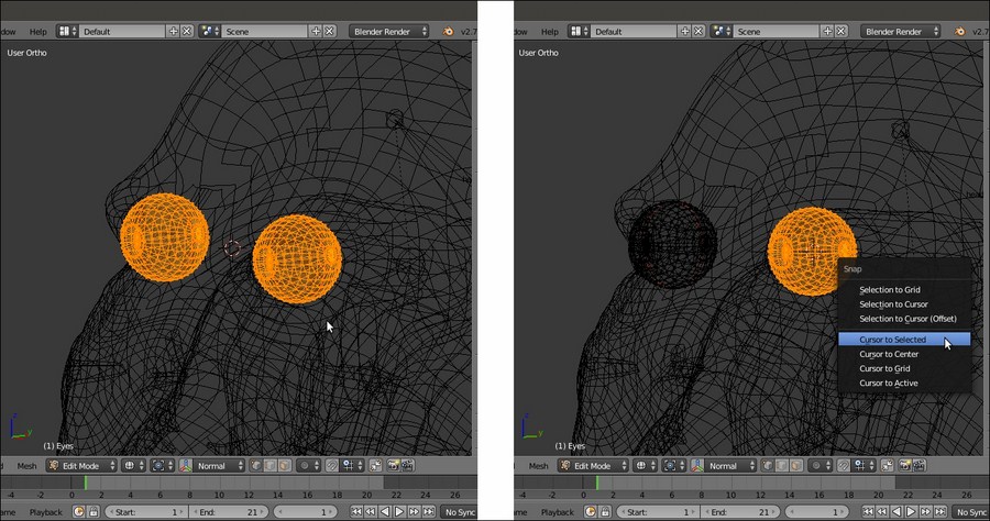
- Get out of Edit Mode and select the Eyes item in the Outliner; press the dot (.) key on the numpad to center the view on the selected object, the Z key to go in Wireframe viewport shading mode, and Tab to go into Edit Mode.
- Press the A key to select all the eye vertices and then box-deselect (the B key and the middle mouse button) the vertices of the right eye; use Shift + S to call the Snap pop-up menu and select the Cursor to Selected item to place the 3D Cursor at the center of the left eye mesh:

Placing the 3D Cursor at the center of the selected vertices
- Get out of Edit Mode, press the 3 key on the numpad to go in the Side view and reselect the Armature item in the Outliner; press Tab to go into Edit Mode, and then use Shift + A to add a new bone at the cursor position. Press G to grab the already selected Head of the new bone and move it close to the center of the eye to resize it smaller.
- Get out of Edit Mode and select the Eyes item; enter Edit Mode and deselect all the vertices except for the external last iris edge-loop. Then, press Shift + S | Cursor to Selected and get out of Edit Mode.
- Again, select the Armature, go into Edit Mode, be sure that the Head of the new bone is still selected, and press Shift + S | Selection to Cursor:

Placing the bone's head at the iris center location
- Rename the new bone as eye.L and in the Relations subpanel under the Bone window, parent it to the head bone (not Connected), or use Shift to select the eye.L and head bones and press Ctrl + P | Keep Offset.
- Now, select the Tail of the eye.L bone and press Shift + S | Cursor to Selected to put the 3D Cursor on it, and then press the period (.) key to switch the Pivot Point around the 3D Cursor; select the whole eye.L bone and use Shift + D to duplicate it, and soon after, click with the right mouse button to leave the duplicated bone untouched; rotate it 10 degrees clockwise on the cursor position (Shift + D | right-click | R | X | 10 | Enter).
- Rename the new bone as eyelid_upper.L.
- Reselect the whole eye.L bone and repeat the duplication procedure; rotate the new duplicate 10 degrees counterclockwise (Shift + D | right-click | R | X | -10 | Enter).
- Rename the new bone as eyelid_bottom.L (in the following screenshot, all the three new bones—eyelid_upper.L, eye.L, and eyelid_bottom.L—have been selected just to enhance their visibility):

The bones for the eye and eyelids
- Now, duplicate the head bone, resize it smaller, and move it to the joining of the tongue with the inner mouth; rename it from head.001 to tongue.001 and in the Relations subpanel, change its parenting from neck to mand.
- Select the Head of the tongue.001 bone and press the E key to extrude 4 new bones:

The tongue bones
- Rename them accordingly, and then use Shift to select from the tongue.001 to tongue.005 bones and press Ctrl + R; move the mouse pointer horizontally to roll them on their y axis by 180° (hold Ctrl to constrain the rolling to intervals of 5 degrees; alternatively, the roll value can also be set by typing it in the Roll button in the Transform subpanel under the 3D viewport Properties sidepanel).
At this point, the basic rig building process is almost done, even if it is only for the left-half part of the mesh:
- Get out of Edit Mode and press Shift + S | Cursor to Selected to place the 3D Cursor at the median pivot point of the Armature.
- Go back into Edit Mode, select only the left-half part bones and not the median ones (meaning: leave the hips, spine, neck, head, mouth, and tongue bones unselected), press Shift + D to duplicate them, and then right-click with the mouse button; press Ctrl + M, then the X key to mirror the duplicated bones on the x axis, in order to build the missing right-half part of the rig:

Mirroring the duplicated bones on the x axis
- With the duplicated bones still selected, go to the 3D window toolbar and click on the Armature item; in the pop-up menu, select the Flip Names item to automatically rename them with the correct .R suffix:

Renaming the suffix of the duplicated bones
As a very last thing for this recipe, we must verify that the alignment of the bones, especially the last duplicated ones, is correct and, just in case, recalculate the roll rotation, that is, the rotation around the y axis of the bone itself.
- In the Object Data window, under the Display subpanel, check the Axes item to make the bones orientation axes visible (only in Edit Mode and Pose Mode) in the 3D view.
- Select all the bones and press Ctrl + N to recalculate the rolling of all of them; in the Recalculate Roll pop-up menu, there are several different options: because basically the z axis of the bones must match from the left to the right side of the whole rig, with the Armature (and the mesh) oriented along the y global axis, as in our Gidiosaurus case, the first top item, Local X Tangent, can be a good start.
By the way, it is good practice to not trust this automated procedure alone, because sometimes it can give inconsistent results; so, do the following:
- After the recalculation, check that the axes of each bone are actually correctly orientated in a consistent way; effectively, there are some bones that didn't get consistently oriented, meaning that their x and z local axes are oriented differently from the other bones.
- In this case, select the incorrectly oriented bone, press Ctrl + R, and move the mouse to change the rolling; press the Ctrl key to constrain the rolling to intervals of 5 degrees. Alternatively, select the wrong bones, and then use Shift to select one bone that is correctly oriented and press Ctrl + N | Active Bone to copy the rolling from the last selected bone.
By enabling the X-Axis Mirror item in the Armature Options tab under the Tool Shelf, you can recalculate only the bones of one side; the other side bones will follow automatically.
If you want to make sure the bones' orientations are correct and everything is going to work in animation, just go into Pose Mode and rotate one bone, for example leg.L, and then click on the Copies the current pose of the selected bones to copy/paste buffer button (Ctrl + C), which is the first left one of the last three buttons to the right-hand side of the viewport toolbar; then, select the symmetrical bone, leg.R, and click on the last right button to paste the flipped pose (Ctrl + Shift + V); if the leg.R bone rotates correctly, then the orientation is OK:

Recalculating the roll of incorrectly oriented bones
- Now, go to the Object Data window under the main Properties panel and under Display, switch again the bones visualization from Octahedral to B-bone; select the bones and by pressing Ctrl + Alt + S, scale the B-bones smaller or bigger, depending on the visual effect you want to obtain:

The almost completed Armature in B-bones visualization
- Press Ctrl + Tab to pass directly from Edit Mode to Pose Mode and select the forearm.L bone; in the Deform subpanel under the Properties panel, set the Segments for the Curved Bones to 12, and then set the Ease In and Ease Out values to 0.000.
- Repeat this for the forearm.R bone and also for the calf.L and calf.R bones; repeat also for the arm.L, arm.R, leg.L, and leg.R bones.
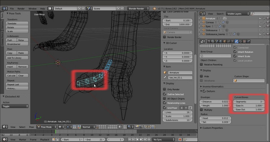
In the following screenshot, all the eight B-bones have been selected to make them more visible. By the way, the highlighted leg.R bone is the active one and shows the Curved Bones setting in the highlighted Deform subpanel to the right-hand side of the screen.

The Segments setting for the leg bone
- Select the toe_inn_02.L bone and in the Deform subpanel under the Properties panel, set the Segments to 6 and leave the Ease In and Ease Out values to 1.000.
- Repeat this for the toe_ext_02.L bone; then, do the same also to the toe_inn_02.R and toe_ext_02.R bones.
- Select the toe_inn_01.L bone and set the Segments to 3; leave the Ease In and Ease Out values to 1.000.
- Repeat for the toe_ext_01.L bone; then, do the same also to the toe_inn_01.R and toe_ext_01.R bones:

The Segments setting for the toes bones
- Save the file.
Although it's often a really time consuming task, the handmade rigging is quite self-explicative; it is, however, better to explain some of the concepts behind this.
The proper renaming of the bones is important, considering that each deforming bone will affect a vertex group sharing the same name on the mesh; although in some cases, as for the tongue bones, the bone naming process can be automated in some way, usually it is better to spend time in giving meaningful names to each bone, in order to avoid mistakes in the following skinning process.
It's also very important to build the hierarchy of the bones so that a bone at a higher level can lead all of the children bones, as it would be in a real skeleton (that is, for example, the hand bone leads all the fingers bones, the forearm bone leads the hand bone, and so on).
Parenting a bone and then obtaining the others by extruding and/or duplicating simplifies the work because an extruded bone is automatically parented to the bone it has been extruded from, and a duplicated bone obviously inherits the parenting of the original one; in the case of the tongue.001 bone, extruding the others has given us a chain with bones automatically parented and named as tongue.002, tongue.003, tongue.004, and tongue.005.
B-bones are both a visualization mode for the bones and a way of working; B-bones, in fact, can work inside a chain as splines, which means that the bones are curved according to the number of Segments and the values of the Ease In and Ease Out items. For the bones of the arms and legs, we have set the Ease In and Ease Out values to 0.000 (default is 1.000; maximum is 2.000), in order to have the B-bones rotating only on their y axis but remaining straight along their length, and hence, mimic the twisting by not only the rotation (pronation and supination of the lower arm) of both the Ulna-Radius and Tibia-Fibula articulation complexes, but also the (limited) rotation of Femur and Humerus.
In some way, B-bones can work as a kind of simulation for a very basic muscle system; in the following screenshot, you can see their effect on the skinned mesh for the forearm by rotating the hand.L bone on the local y axis (to enhance the visibility of the mesh surface's modifications, the wireframe over solid drawing item has been enabled in the Display subpanel under the Object window):

The effect of the rotation of the hand bone on the forearm B-bone and skinned mesh
Here is the effect of the rotation of the forearm.L bone on the Gidiosaurus high arm:

The effect of the rotation of the forearm bone on the upper arm b-bone and skinned mesh
The effect acts on the shin as well, by rotating the foot.L bone on the global z axis:

The same effect obtained on the calf b-bone by rotating the foot on its local y axis
Also, the same effect acts on the thigh by rotating the calf.L bone:

The same effect obtained on the leg b-bone by rotating the calf
Note that the Gidiosaurus is a digitigrade biped humanoid: the bones that, from our plantigrade point of view, look like the foot are actually the toes, while the almost vertical structure that we would call an ankle is the real foot (this is a very common condition among the majority of the terrestrial animals, both still alive and extinct).
