
UART stands for Universal Asynchronous Receiver/Transmitter. It is one of the first modes of communication to computers: it goes back to 1960, when it was used to connect minicomputers for teletypewriter machines (teletypes). The main purpose of UARTs is to transmit and receive the serial data just like a standalone integrated circuit; it is not a protocol as SPI (Serial Peripheral Interface) or I2C (Inter-Integrated circuit). It is typically used by manufacturers to connect microcontrollers to store and load programs. Every UART device has its own advantages and disadvantages. The following are the advantages of UART:
- Two wires only, so pretty straightforward one is transmit (TX) and another is Receive (RX)
- There is no need for a clock signal
- Error checking can be performed by parity bit
- If both sides are set up then the structure of the data packet can be changed
- Widely used due to the availability of its documentation throughout the internet
It has the following limitations:
- Testers cannot increase the data frame: it will be limited to 9 bits at most
- There is no way to set up multiple slave or master systems
- UART baud rates must be within 10%
In this section, we will using the USB to TTL (Transistor/Transistor Logic) adapter to perform UART communication by connecting to the serial port of the device's circuit board.
These adapters typically include four ports:
- GND: Ground (0V) supply
- VCC: Voltage Power supply, 3.3V (default) or 5V
- TX: Serial Transmit
- RX: Serial Receive
One big challenge attackers would face during a hardware hack is to identify the right serial ports. This could be done by using a multimeter to read the output of voltage to confirm the TX (typically voltage will keep fluctuating when device powered on), RX (initially it will fluctuate, but will be constant after a point), and GND (zero voltage).
In this example, we will use a well-known wireless router and connect UART to TTL to communicate to the hardware directly, as shown in the following image:

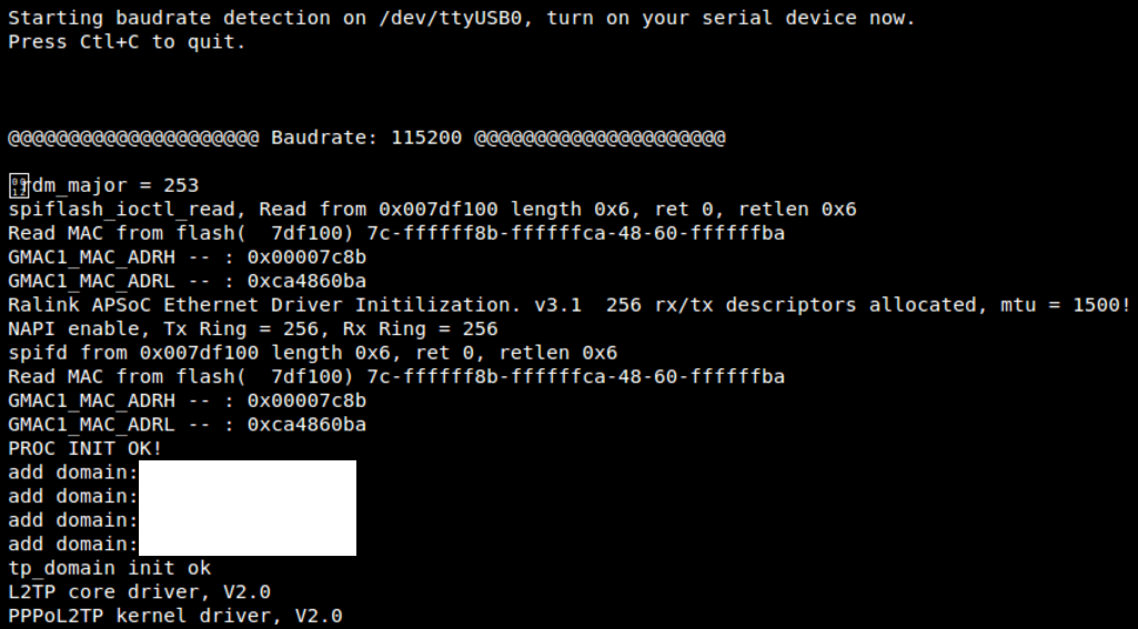
When the right TX/RX and ground is identified, we can go ahead to learn in Kali Linux about the device that is currently connected by running the baudrate.py Python file (https://github.com/PacktPublishing/Mastering-Kali-Linux-for-Advanced-Penetration-Testing-Third-Edition/blob/master/Chapter%2014/baudrate.py). If the serial device is connected, you should be able to see the following screen in your Kali without any issues. Most of the time, the configuration of 115200 baud rate works for routers:
Once the device is successfully read by our Kali Linux, we can start interacting with the device by running screen /dev/ttyUSB0 115200 in the command line, which should directly provide shell access as shown in the following screenshot. Testers have to note that in this example we have used a known router that provides straight root access, which might not be the same case in other devices. Devices manufactured in recent times, will prompt to enter username and password.

It is always a good way to understand the device from the debug logs: we have seen hardcoded credentials in plenty of IoT devices.