
Chapter 5: Implementing Node-RED Locally
In this chapter, let's use the standalone version of Node-RED. Node-RED consists of a development environment, an execution environment, and the application itself. You can understand the mechanism by using the standalone version that runs in the local environment.
Specifically, the most common reason for starting the standalone version of Node-RED is when using it on an IoT edge device. IoT edge devices have sensors that are usually applied to the "Things" part of the "Internet of Things." In this chapter, we will look at the sensing data within the edge device and create a sample flow.
Let's get started with the following four topics:
- Running Node-RED on a local machine
- Using the standalone version of Node-RED
- Using IoT on edge devices
- Making a sample flow
By the end of this chapter, you will have learned how to build a flow for handling sensor data on IoT devices.
Technical requirements
To progress through this chapter, you will need the following:
- Node-RED (v1.1.0 or above): https://nodered.org/
- Raspberry Pi: https://www.raspberrypi.org/
The code used in this chapter can be found in Chapter05 folder at https://github.com/PacktPublishing/-Practical-Node-RED-Programming.
Running Node-RED on a local machine
We can now create the flow for sensing data on an IoT edge device, and in this scenario, the local machine uses Raspberry Pi. The reason for this will be described in the Using the standalone verison of Node-RED section, but in summary, this tutorial is for IoT edge device.
I have already explained how to start Node-RED on Raspberry Pi, so you should now know how to run it, but if you need a refresher, please refer to the Install Node-RED for Raspberry Pi section in Chapter 2, Setting Up the Development Environment.
Now, follow these steps to start Node-RED on your Raspberry Pi:
- Let's start by executing Node-RED from the Raspberry Pi menu:
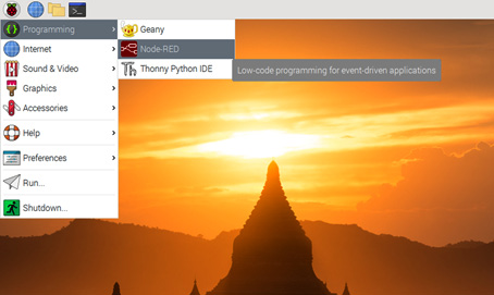
Figure 5.1 – Running Node-RED from the Raspberry Pi menu
- You can check the status of Node-RED on your terminal. If Started flows is shown, Node-RED is ready to use:
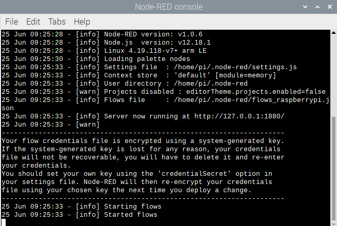
Figure 5.2 – Terminal of Raspberry Pi
- You can access the Node-RED flow editor with the localhost:1880 URL:

Figure 5.3 – Node-RED flow editor
Let's learn a few concepts before making use of the flow editor.
Using the standalone version of Node-RED
Now we will learn what the standalone version of Node-RED is and how it differs from other versions. We usually use the Node-RED flow editor as a standalone editor; however, we can also use the Node-RED flow editor on any cloud with container technologies such as Docker, Kubernetes, or Cloud Foundry. We will explicitly demonstrate the use of the standalone version with relatively common use cases to learn how to use it.
Let's think about situations where Node-RED is used.
Node-RED is a tool for creating applications made with Node.js. It is also the execution environment. If you can write an application in Node.js, that's fine.
So, why build an application with Node-RED?
One answer is to black-box each individual unit of data processing. This makes the role of each process very clear and easy to build and maintain.
Another answer is to avoid human error. Since each process is modularized as a node, you only need to understand the input/output specifications when using that process. This means you can avoid human errors such as coding mistakes and missing test specifications. This can be the advantage of no-code/low-code as well as Node-RED.
Next, imagine a concrete situation that uses Node-RED with the characteristics just described.
Think of a business logic that controls data and connects it to the next process. This is a common situation in IoT solutions.
The standard architecture for IoT solutions is built with edge devices and cloud platforms. It sends the sensor data acquired by the edge device to the cloud and then, on the cloud work to process the data, such as visualizing, analyzing, and persistent.
In this chapter, I would like to focus on that edge device part.
It is common for edge devices to want to prepare the acquired sensor data to some extent before sending it to the cloud. The reason for this that if you send all the acquired data, there is a risk that the network will be overloaded.
So, the standalone Node-RED exercise uses Raspberry Pi, which is a famous IoT infrastructure for consumers.
In this chapter, we will use the Grove Base HAT for Raspberry Pi and Grove Base modules. This is one of the standards for the IoT edge device platform and so we need to install the Grove Base driver to Raspberry Pi.
Important Note
This chapter gives an example using Grove Base HAT, which is relatively inexpensive and can be purchased (the link to this is mentioned in the next section), but any sensor device that can be connected to a Raspberry Pi can handle data on Node-RED.
When using a module other than the Grove Base HAT sensor device, use the corresponding node and read this chapter. (Implementation is required if there is no corresponding node.)
You can check the Node-RED library for the existence of a node that corresponds to each device:
Let's prepare to use Grove Base HAT on our Raspberry Pi by following these steps:
- Let's start by executing the following command on our Raspberry Pi:
$ curl -sL https://github.com/Seeed-Studio/grove.py/raw/master/install.sh | sudo bash -s -
- If everything goes well, you will see the following notice:
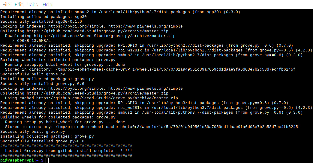
Figure 5.4 – Successful grove.py installation
- The next step is to enable ARM I2C. We can do this by executing the following command:
$ sudo raspi-config
- After executing the command, you will see the following configuration window. Please select Interfacing Options:
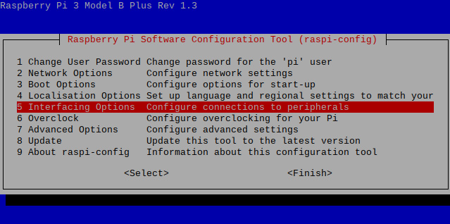
Figure 5.5 – Software configuration tool
- Select I2C:
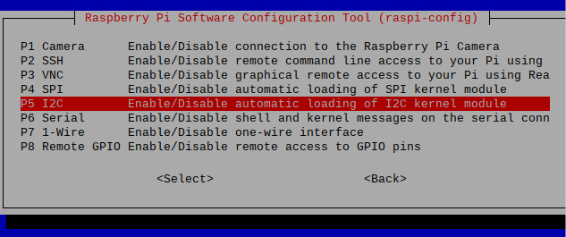
Figure 5.6 – Enabling I2C
- Once you select it, a Would you like the ARM I2C interface to be enabled? message will be shown in the same window. Please select Yes to accept it.
You have now successfully enabled I2C. Restart the Raspberry Pi and restart the Node-RED flow editor. In doing this, your Raspberry Pi has been made available to use the I2C interface, and for the next step, we need to connect the sensor devices and Raspberry Pi via the I2C interface.
Using IoT on edge devices
Now let's consider a case study on edge devices in IoT.
IoT has recently been adopted in several industries, for example, in the fields of weather forecasting and agriculture; however, the basic composition is the same. Various data acquired by the edge device is sent to the server-side platform, such as the cloud, and the data is handled and visualized on the server side, which is full of resources. There are various ways to visualize, but in the simplest case, it will be to output the necessary data values to the log as a standard output.
In this chapter, I would like to consider the edge device part in the use case of IoT. This is about handling the sensor data, acquired using the sensor module, before it goes to the server side for formatting and narrowing down.
What are the different kinds of sensors?
The following sensors are often used at the experimental level of IoT:
- Temperature
- Humidity
- Gyroscope (acceleration, angular velocity)
- Light
- Sound
- Pressure-sensitive
- Magnetic
Here we will consider the use case of outputting the acquired value to the log using a light sensor and a temperature/humidity sensor.
In order to get sensor data, you'll need a device. In this sample flow (application), Raspberry Pi is used, but it does not have a sensing function because it is just a foundation. With the old-fashioned board, you had to solder the sensor device/module, but the convenient thing about the Raspberry Pi is that there are many sensor module kits that can be connected with one touch.
As already introduced, we'll use the Grove series provided by Seeed, which has a sensor module and connection board for Raspberry Pi: https://wiki.seeedstudio.com/Grove_Base_Hat_for_Raspberry_Pi/
Let's prepare the Grove Base HAT for Raspberry Pi modules.
Important Note
If you don't have the Grove Base HAT for Raspberry Pi and want to run this tutorial, please buy it via the official site (https://www.seeedstudio.com/Grove-Base-Hat-for-Raspberry-Pi.html).
This is what the Grove Base HAT for Raspberry Pi looks like:

Figure 5.7 – Grove Base HAT for Raspberry Pi
We need to connect the Grove Base HAT and the sensor modules to the Raspberry Pi. To do so, follow these steps:
- Place the Grove Base HAT on your Raspberry Pi and screw it in:

Figure 5.8 – Setting the Base HAT on your Raspberry Pi
This is what the Grove - Light Sensor v1.2 - LS06-S phototransistor looks like:
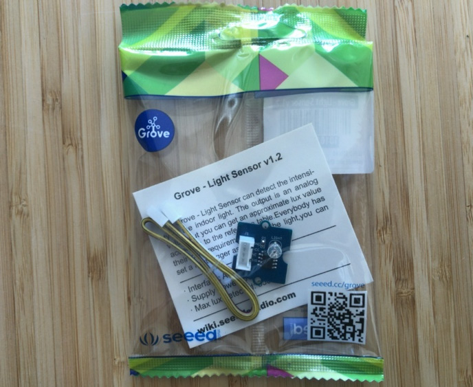
Figure 5.9 – Grove - Light Sensor v1.2
You can get it from https://www.seeedstudio.com/Grove-Light-Sensor-v1-2-LS06-S-phototransistor.html.
- Connect the Grove light sensor to the analog port of your Base HAT:
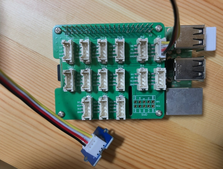
Figure 5.10 – Connecting the light sensor to your Base HAT
Important Note
Please be careful! This vendor, Seeed, has a similar module for temperature/humidity sensor SHT35, but it's not supported by the Grove Base HAT node. You need to use SHT31.
This is what the Grove - Temperature&Humidity Sensor (SHT31) looks like:
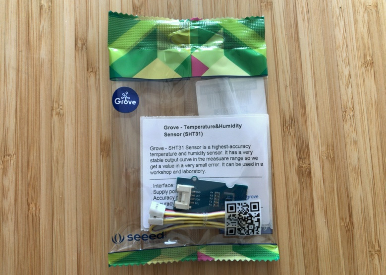
Figure 5.11 – Grove – Temperature&Humidity Sensor (SHT31)
You can get it from https://www.seeedstudio.com/Grove-Temperature-Humidity-Sensor-SHT31.html.
- Connect the Grove temperature and humidity sensor to the I2C port of your Base HAT:
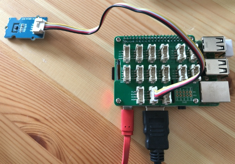
Figure 5.12 – Connecting the temperature/humidity sensor to your Base HAT
And that's it. Now your device is set up and we are ready to go on to the next step! In this part, we have learned about popular, simple use cases of IoT edge devices and next, we will make a flow for these use cases.
Making a sample flow
In this section, we will create these two sensor data output flows in the Node-RED flow editor.
You will use the sensor modules you have prepared to collect data and create a sample flow to visualize it on Node-RED. By using two different sensor modules, we can learn the basics of data handling in Node-RED.
Use case 1 – light sensor
The first is a light sensor. Let's create a flow (application) that detects light and outputs the value detected by a fixed-point observation to a log:
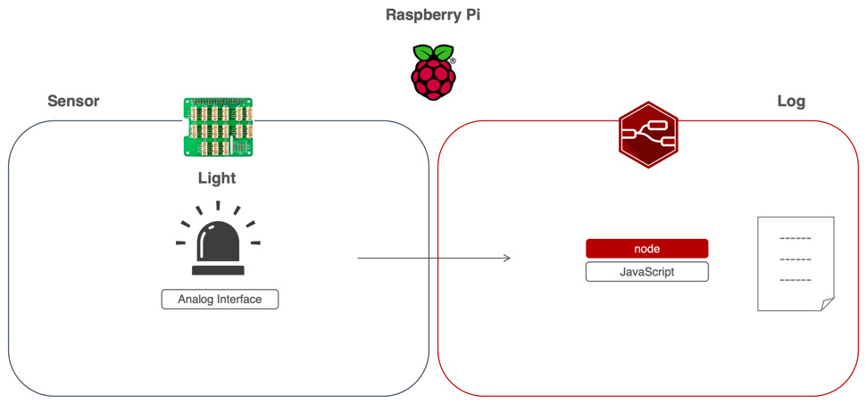
Figure 5.13 – Use case 1 – getting light sensor data
Connect the light sensor module to the Raspberry Pi and use the Node-RED flow editor on the Raspberry Pi to output the data obtained as a standard output.
Use case 2 – temperature/humidity sensor
The second one is a temperature/humidity sensor. Let's create an application (flow) that detects temperature and humidity and outputs the value detected by a fixed-point observation to a log:
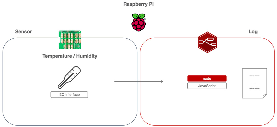
Figure 5.14 – Use case 2 – getting temperature/humidity data
Connect the temperature/humidity sensor module to the Raspberry Pi and use the Node-RED flow editor on the Raspberry Pi to output the data obtained as a standard output.
If you want to spot test these two use cases on your device, you need to connect a sensor that you can use to obtain sensor data.
You may have to prepare this before creating the flow.
This time, we will use Grove Base HAT, which is easy to use with Raspberry Pi, and as this setup was completed in the previous step, we are ready to access the data on Raspberry Pi. However, we have not yet prepared Node-RED. It is difficult to access this data with Node-RED as default. One way is to use a Function node and code the script from scratch, which is very difficult but not impossible.
For handling the sensing data recognized by Raspberry Pi on Node-RED, a "node" dedicated to Grove Base HAT is required.
The good news is that you can start using the node right away. This is because Seigo Tanaka, a Node-RED User Group Japan board member (https://nodered.jp/) and Node-RED contributor, has already created and released a node for Grove Base HAT. This is the node for the Grove Base HAT for Raspberry Pi:
node-red-contrib-grove-base-hat
You can read more about it here: https://www.npmjs.com/package/node-red-contrib-grove-base-hat.
If you need a refresher on how to install nodes that are published on the node library, please read the Getting several nodes from the library section in Chapter 4, Learning the Major Nodes.
The reason I refer you back to this is that the next step is to install the node for the Grove Base HAT from the library into your environment.
Let's enable the use of this Grove Base HAT node in our Node-RED flow editor:
- Click the menu at the top right and select Manage palette to open the settings panel:
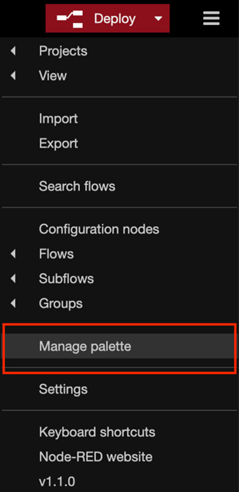
Figure 5.15 – Selecting Manage palette
- When the settings panel is opened, type the name of the node you want to use in the search window. We want to use node-red-contrib-grove-base-hat, so please type the following:
grove base
- After that, you can see the node-red-contrib-grove-base-hat node in the search window. Click the Install button:
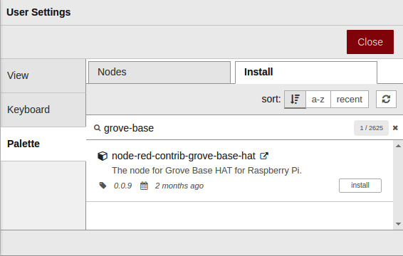
Figure 5.16 – Installing the node-red-contrib-grove-base-hat node
- After clicking the Install button, you will see a message asking you to read the documentation to find out more information about this node. Read the document if necessary, and then click the Install button on the message box:
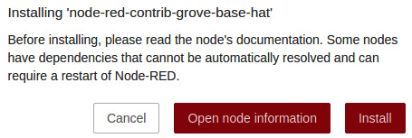
Figure 5.17 – A message window to read the node documentation
Now you are ready to use the node for Grove Base HAT. Check the palette in the flow editor. At the bottom of the palette, you can see that the Grove Base HAT node has been added:
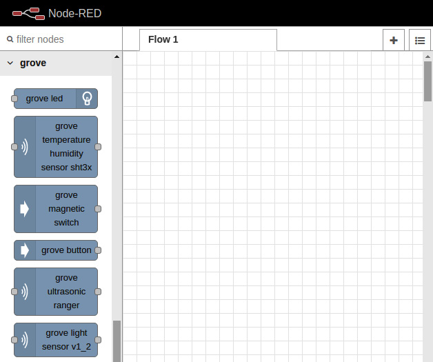
Figure 5.18 – Grove Base HAT nodes on your dashboard
There are many sensing modules that can be connected to Grove Base HAT. This time, only the light and temperature/humidity sensors are used, but there are other things that can be seen by looking at the types of nodes.
The procedure followed for the two use cases created here can also be applied when using other sensors. If you are interested, please try other sensors too. In the next section, we will make a flow for use case 1.
Making a flow for use case 1 – light sensor
In use case 1, Node-RED can be used to handle the illuminance obtained from the light sensor as JSON data. That data can be handled as JSON data, then be sent to the server side afterward, and various processes can be easily performed on the edge device.
The value obtained from the light sensor is received by Node-RED and the output is a debug log (standard output). We can set this using the following steps:
- Select the grove light sensor v1_2 node from the palette on the left side of the flow editor and drag and drop it into the workspace to place it:
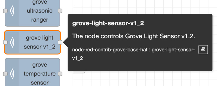
Figure 5.19 – grove light sensor v1_2
This node allows the value of the sensor device, which is continuously acquired on the Raspberry Pi via the Grove Base HAT, to be handled as a JSON format message object on Node-RED.
- After placing the grove-light-sensor-v1_2 node, place the inject node and debug nodes and wire them so that the grove-light-sensor-v1_2 node you placed is sandwiched between them:
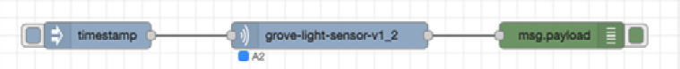
Figure 5.20 – Placing nodes and wiring them for the light sensor
- Next, check the settings of the grove-light-sensor-v1_2 node. Double-click the node to open the settings panel.
- There is a selection item called Port in the settings panel. A0 is selected by default.
This Port setting is to specify which connector on the Grove Base HAT gets data from the connected module.
- Earlier, we connected the Grove light sensor to the Grove Base HAT. If the connection is made according to the procedure in this tutorial, it should be connected to port A2, so select A2 as the node setting value. If you are connecting to another port, select the port you are connecting to:

Figure 5.21 – Select A2 as the port if you connected the sensor to A2 of Base HAT
- After checking and setting Port on the settings panel, click the Done button in the upper-right corner to close the settings panel.
That's it! Don't forget to click the deploy button.
You should remember how to execute a flow from a inject node, because you learned about this in the previous chapter. Click the switch on the inject node to run the flow. The data for the timing when the switch is clicked is outputted as a log, so please try clicking it a couple of times.
Important Note
Do not forget to display the debug window to show that the value of the acquired data will be the output to the debug window. Node-RED does not automatically show the debug window even if the debug output is activated.
The resulting output in the debug window looks like the following:

Figure 5.22 – Result of the light sensor flow
You can see that the result was output to the debug window.
Congratulations! With this, we have successfully created a basic flow (application) that handles the value of our first light sensor with Node-RED.
You can also download this flow definition file here: https://github.com/PacktPublishing/-Practical-Node-RED-Programming/blob/master/Chapter05/light-sensor-flows.json.
Making a flow for use case 2 – temperature/humidity sensor
In use case 2, Node-RED can be used to handle the temperature and the humidity obtained from the temperature/humidity sensor as JSON data. The data, which can be handled as JSON data, can be sent to the server side afterward, and various processes can be easily performed on the edge device.
The value obtained from the temperature/humidity sensor is received by Node-RED and is outputted as a debug log (standard output):
- Select the grove temperature humidity sensor sht3x node from the palette on the left side of the flow editor and drag and drop it into the workspace to place it:
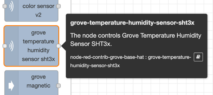
Figure 5.23 – grove temperature humidity sensor sht3x
This node allows the value of the sensor device, which is continuously acquired on the Raspberry Pi via Grove Base HAT, to be handled as a JSON format message object on Node-RED.
- After placing the grove-temperature-humidity-sensor-sht3x node, place the inject and debug nodes, respectively, and wire them so that the grove-temperature-humidity-sensor-sht3x node you placed is sandwiched between them:
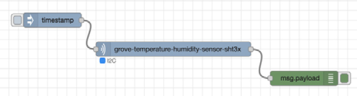
Figure 5.24 – Placing the nodes and wiring them for the temperature and humidity sensor
- Next, check the settings of the grove-temperature-humidity-sensor-sht3x node and double-click the node to open the settings panel.
Actually, this node has no values to set (strictly speaking, the name can be set, but the presence or absence of this setting does not affect the operation):

Figure 5.25 – Already set to the I2C port
You can see on the settings panel that the port is designated as I2C (not changeable). If you have connected the Grove temperature and humidity sensor to the Grove Base HAT according to the procedure in this document, the module should be correctly connected to the I2C port. If it is connected to a port other than I2C, reconnect it properly.
- After checking Port on the settings panel, click the Done button in the upper-right corner to close the settings panel.
That's it! Don't forget to click the deploy button.
- Click the switch on the inject node to run the flow. The data for the timing when the switch is clicked is outputted as a log, so please try clicking it a couple of times.
Important Note
As noted in the previous section, do not forget to display the debug window to show that the value of the acquired data will be the output to the debug window. Node-RED does not automatically show the debug window even if the debug output is activated.
The resulting output in the debug window looks like the following:

Figure 5.26 – Result of the temperature/humidity sensor flow
You can see that the result was outputted to the debug window.
Congratulations! With this, we have successfully created a basic flow (application) that handles the value of the second sample, the temperature/humidity sensor, with Node-RED.
You can also download this flow definition file here: https://github.com/PacktPublishing/-Practical-Node-RED-Programming/blob/master/Chapter05/light-sensor-flows.json.
Well done! Now you have learned how to handle the data obtained from the illuminance sensor and temperature and humidity sensor in JSON format on Node-RED.
Summary
In this chapter, you learned how to create a sample flow (application) by comparing Node-RED to a real IoT use case. We experienced using the sensor module and Raspberry Pi to exchange data with Node-RED, so we had a feel for IoT.
The flow steps created here will help you create different flows with other sensor modules in the edge device in the future.
In the next chapter, we will use the IoT use case as we did this time, but we will create a practical sample flow (application) on the cloud side (server side).