
Chapter 7: Creating a Clap Switch
When it comes to automating the home, one of the most desired features is often the ability to switch electronic devices on and off remotely (Colon, 2020). To address this, in this chapter – which covers the fifth project in this book – we will learn how to build a wireless electronic remote control to turn an LED on when two successive clapping sounds are detected using a simple microphone (clap switch). The next two successive clapping sounds detected will turn the LED off. The importance of having a switch clap remote control is that an electronic appliance can be turned on and off from anywhere in a room. This characteristic makes it of particular interest to the elderly or people with a motor disability.
This chapter will cover the following main topics:
- Connecting a microphone to a microcontroller board port
- Coding your clap switch sketch
- Coding a clap switch with two clapping sounds
- Coding a clap switch with a timer between claps
- Improving the project performance
After completing this chapter, you will be able to apply what you have learned to projects that need to read data from an analog source, process this data to convert it to digital data, and thus be able to use it to automate processes.
Technical requirements
The hardware components that will be needed to develop the clap switch are as follows:
- One breadboard
- One electret microphone FC-04 module
- Seven male-to-male jumper wires
- One LED
- One 220-ohm resistor
- A 5-volt power source
These components are very common, and there will be no problems in getting them easily. On the software side, you will require the Arduino IDE and the GitHub repository for this chapter: https://github.com/PacktPublishing/DIY-Microcontroller-Projects-for-Hobbyists/tree/master/Chapter07
The Code in Action video for this chapter can be found here: https://bit.ly/3h2xjQu
To supply the power source, you can use power adapters (Figure 7.1) that fit into the breadboard rails (these power adapters or breadboard power supplies are common and can be purchased at a low price in online stores), can be jumpered to provide 3.3 or 5 volts, and include an on/off button:
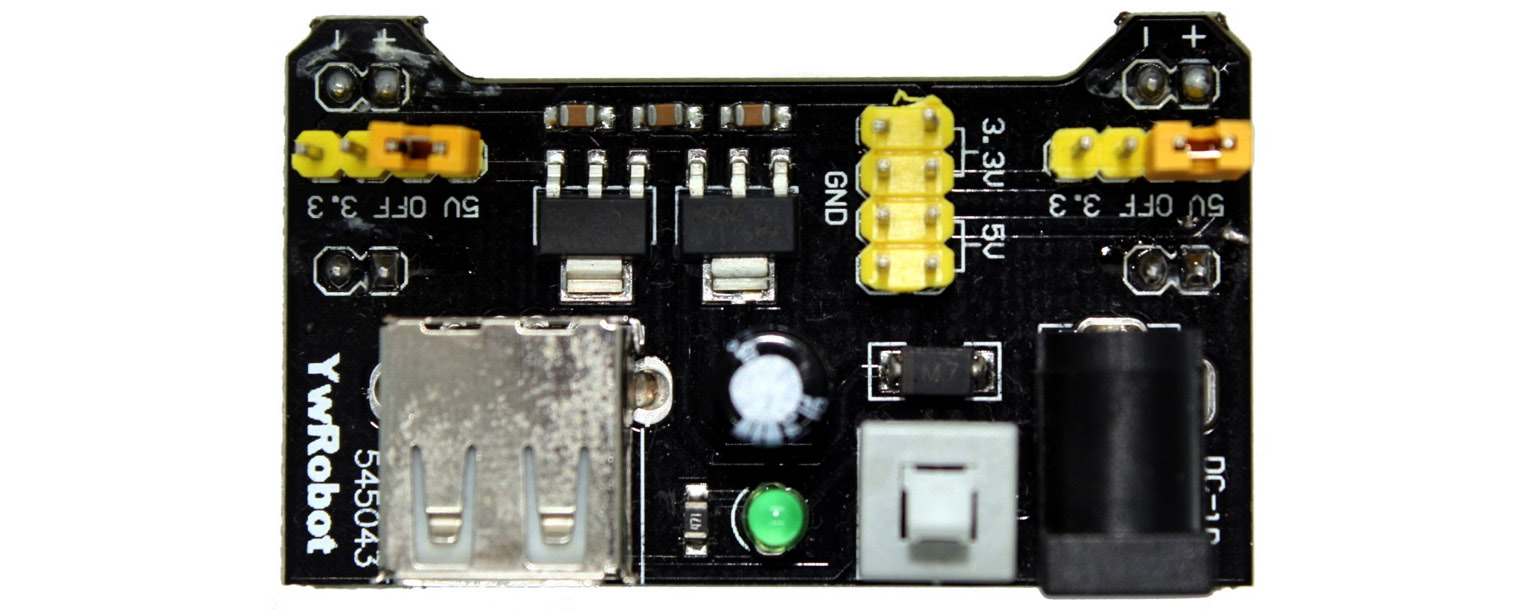
Figure 7.1 – Power supply
Additionally, you can use a 9-volt battery. Using these batteries is one of the most common options since the 9-volt voltage is appropriate to power up projects with microcontrollers such as the Blue Pill STM32.
Connecting a microphone to a microcontroller board port
In this section, we are going to learn about the hardware components needed to build a clap switch using the STM32 Blue Pill and the microphone FC-04 module.
However, before we begin connecting the components, we must understand the basics of a microphone.
Understanding the electret microphone module
A clap switch uses a microphone to sense the environment while waiting for an event that will trigger an action. In this section, we will understand how to apply this functionality in a project.
We will use a generic microphone module, which is a breakout board with an electret condenser microphone (as shown in Figure 7.2):
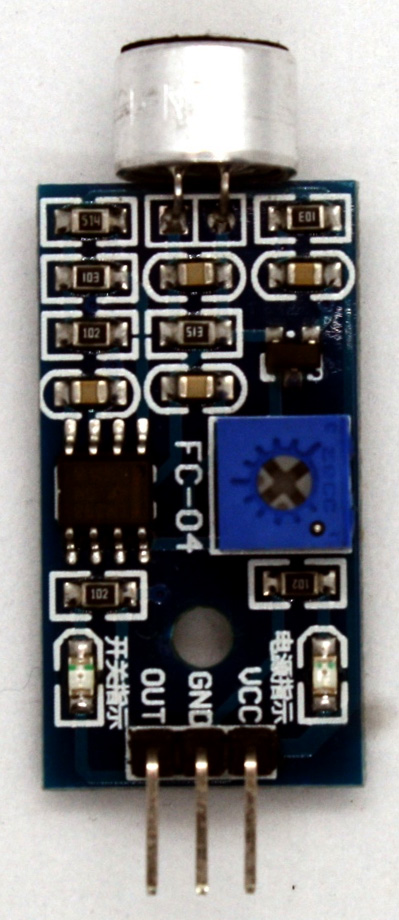
Figure 7.2 – Electret microphone board
Condenser microphones are composed of a diaphragm membrane on a plate, and both are conductors. Condensers are essentially capacitors formed of conductors and insulation between them. Therefore, when there is a smaller distance between these two conductors, a higher capacitance is obtained.
Important note
Capacitance is the property or capacity that an electronic component has to collect and store energy in the form of an electrical charge.
The microphone receives the sound, making the diaphragm vibrate. The vibration varies the distance between the conductors and changes its capacitance to produce a voltage charge, which in turn requires a lot of voltage to maintain, making traditional microphones ineffective for projects with microcontroller boards (such as the Blue Pill or the Curiosity Nano) in reducing power consumption. To address the issue of the high amount of power consumption, electret microphones were developed. Electret microphones use a unique polarized material charged during their manufacturing process, thus not requiring external voltage (Fox, 2020). With an understanding of microphone basics, we will now move on to the steps to connect a microphone to a microcontroller board.
Connecting the components
Now we are going to connect the electronic components to the breadboard, do the wiring, and finally connect everything to the STM32 Blue Pill:
- In connecting the components, place the electret microphone, the resistor, the LED, and the STM32 Blue Pill on a breadboard with enough space to add the wiring layer, as shown in Figure 7.3. The hardware connections for this project are very straightforward:

Figure 7.3 – Components on the breadboard
- Next, to power up the clap switch with an external power source, connect the 5-volt pin to the red rail on the breadboard and a ground pin to the blue track, as shown in the following photo (Figure 7.4):
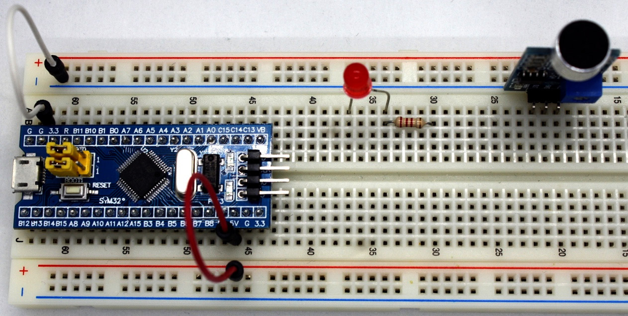
Figure 7.4 – Connections to the power supply
- Connect the ground (GND) pin of the sensor to the blue rail (the holes next to the blue lines) of the breadboard or a GND terminal of the SMT32 Blue Pill. Next, you need to connect the voltage (VCC) pin to the red rail (the holes next to the red lines) of the breadboard, or the 5V bus of the Blue Pill, as shown in the following figure. The sensor generates an analog output, so it must be connected to an analog input on the Blue Pill card and connect the output pin of the sound sensor to pin A0 of the Blue Pill, as shown in Figure 7.5:
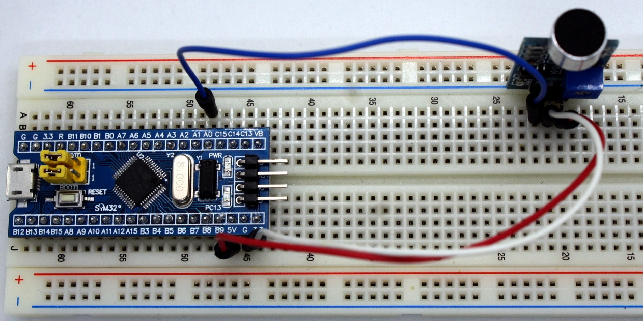
Figure 7.5 – Microphone connection
In this way, the acquisition of the analog signal that comes from the sensor will be achieved, and the microcontroller will convert it into digital.
- To configure the LED, connect the cathode of the LED to a GND pin of the Blue Pill and the anode to pin 13 of the Blue Pill. The resistor must be between these two as this is a digital output pin (see Figure 7.6):
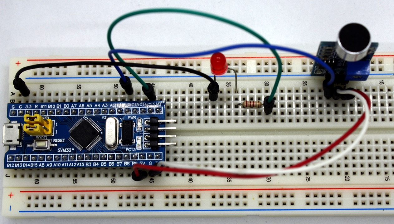
Figure 7.6 – LED setup
Finally, you need to use a power source such as batteries or the ST-LINK connected to the USB port of the computer to power up the board. The ST-LINK will also serve to upload the scripts to the microcontroller board. Figure 7.7 summarizes all the hardware connections:
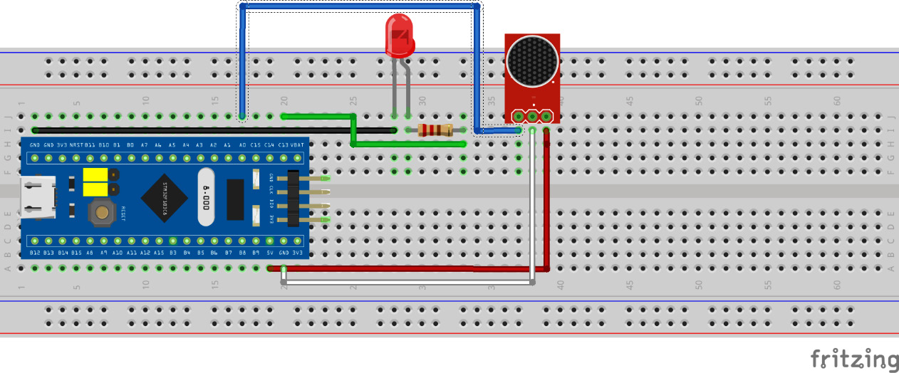
Figure 7.7 – Circuit for the microphone sensor connection
The previous figure shows all the connections between the STM32 Blue Pill and the electronic components. This figure summarizes the connection steps we just completed.
Figure 7.8 presents the schematics for this project:
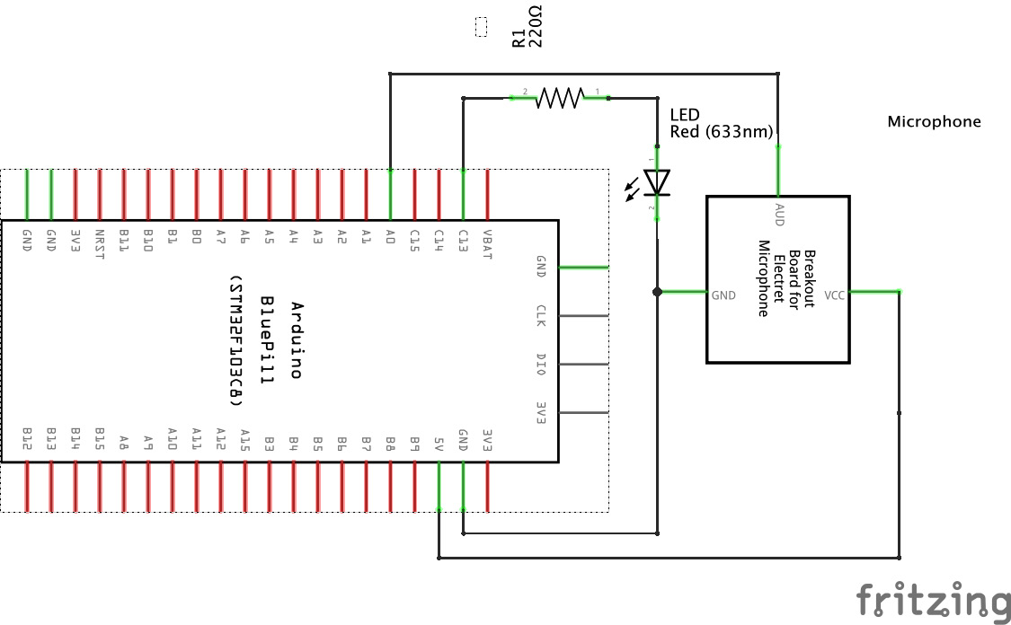
Figure 7.8 – Schematics for the microphone sensor connection
The schematics figure shows the electric diagram for the complete project. Figure 7.9 shows how everything is connected in our do it yourself (DIY) clap switch:
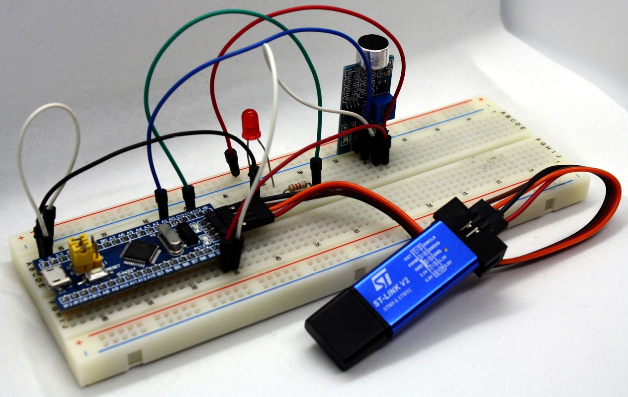
Figure 7.9 – Clap switch device
Figure 7.9 shows how all the finished hardware connections will look.
Now, let's move on to the next section, which will detail the essential parts of the C code to complete the functionality of the clap switch.
Coding your clap switch sketch
In this section, we will develop the program to identify a clap sound from a microphone. This sound will turn an LED on and off. Let's get started:
- As a first step, we need to define which pins of the Blue Pill card pins will be used for input and output. Then, we need to assign the sound threshold level for the microphone to detect the sound; this value is in the range 0-1023. We are using a value of 300, so the sound captured by the microphone is loud enough to identify a clap and not any background noise (we will show how to select an appropriate threshold in the Improving the project performance section).
As can be seen in the following code snippet, the analog reading pin will be 0 (labeled A0 on the Blue Pill), and the digital output pin will be PC13 (labeled C13 on the Blue Pill):
const int MicAnalogPin = 0;
const int LedDigitalPin = PC13;
const int ClapThreshold = 300;
Constant value variables are being used with the const keyword to assign its value. Another way to do it is with a preprocessor macro using #define, as shown in the following code snippet:
#define MicAnalogPin 0
#define LedDigitalPin PC13
#define ClapThreshold 300
The difference between both forms is that with #define, the compiler replaces all occurrences with the values before compilation to avoid memory usage in the microcontroller and will always have a global scope. In contrast, const is a constant value variable stored in the microcontroller memory and has a limited scope.
Based on best programming practices, the recommended option for type safety is the use of constant variables, given that the #define directive substitutes the macro value disregarding the scope, which can lead to data type problems. In contrast, const will always be of the same data type that was defined in its declaration.
- Next, in the setup() part, we need to start the serial data transmission and assign the speed of the transfer (9600 bps as a standard value):
void setup() {
Serial.begin(9600);
}
- We also need to configure which pins the microcontroller will use as input and output. These values were previously defined in the constants. In the following code, the assignment is made to the microcontroller card:
void setup() {
Serial.begin(9600);
pinMode(LedDigitalPin, OUTPUT);
pinMode(MicAnalogPin, INPUT);
}
- Now comes the loop() part in the sketch. It contains two main parts: the reading of the analog input pin and the clap detection to turn on the LED.
- The analogRead() function reads the value of the previously defined input pin:
void loop() {
int SoundValue = analogRead(MicAnalogPin);
Serial.print("Sound value: ");
Serial.println(SoundValue);
}
- Now we have the read value from the microphone in the SoundValue variable; the next step will be to compare its value with the defined threshold. If the sound input by the microphone is higher than the threshold, the LED will light up, and a 1-second pause will occur, in which you can observe that the LED is lit. If the detected sound does not exceed the threshold value, the LED will be instructed to remain off. In both cases, the serial console will display the status of the running script:
void loop() {
int SoundValue = analogRead(MicAnalogPin);
Serial.print("Sound value: ");
Serial.println(SoundValue);
if (SoundValue > ClapThreshold) {
Serial.println("A clap was detected");
digitalWrite(LedDigitalPin, HIGH);
delay(1000);
} else {
Serial.println("No clap detected");
digitalWrite(LedDigitalPin, LOW);
}
}
Now we have the complete code for the first sketch to detect the sound of a clap and turn on a LED. Next, we can see the complete sketch, which is available in the Chapter7/clap_switch folder in the GitHub repository.
Now that the sketch is complete, you can upload it to the Blue Pill board. To test that our project works, just give a clap to see how the LED turns on. Do not forget that the breadboard must be powered, either by batteries or connected to the computer.
So far, we have learned how to read an analog value (sound) from a microphone with a microcontroller. During the main loop, the device keeps listening to the microphone to detect whether any sound (we will assume the detected sound is a clap) is louder than the defined threshold; if so, an LED lights up. If not, the microcontroller will keep the LED off.
Next, we are going to modify the sketch to indicate to our clap switch to wait for two claps before turning on the LED. For better organization, we will create a copy of the code to compare with the original sketch or in case we need to revert to the previous version when experiencing an issue with the new code.
Coding a clap switch with two clapping sounds
In this section, we will modify our program to identify two clapping sounds from the microphone. This will allow us to be more precise before activating the remote control:
- Once we define the constants, we define two variables: the integer type, to count the number of claps, and the Boolean type, to know the status of the LED (on or off). For a better reading, we have highlighted the changes to the original variables' declaration of the sketch:
const int MicAnalogPin = 0;
const int LedDigitalPin = PC13;
const int ClapThreshold = 300;
int ClapNumber = 0;
bool LedState = false;
As you can see, the clap count is set to 0, and the LED status to false (off), which means that true will be on.
- We will leave the setup() section unchanged and continue to the loop() section, where we have the most important logic changes. We will modify the instructions that are within the conditional sentence that verifies whether the sound registered by the microphone is louder than the defined threshold:
void loop() {
int SoundValue = analogRead(MicAnalogPin);
if (SoundValue > ClapThreshold) {
ClapNumber++
delay(500);
}
}
This conditional block does not require an else sentence. Also, the instruction to turn on the LED has been removed. If a clap is detected, the clap counter will be incremented by 1 and will wait for a half-second pause before the Blue Pill re-senses the microphone.
- We need to know whether the total number of claps is 2, so we must write another condition in our sketch to ask whether the ClapNumber variable already has the two claps registered; if so, it must turn on the LED:
void loop() {
int SoundValue = analogRead(MicAnalogPin);
if (SoundValue > ClapThreshold) {
ClapNumber++;
delay(500);
}
if (ClapNumber == 2) {
digitalWrite(LedDigitalPin, HIGH);
}
}
Now we are ready to test the new sketch on our device, compile it, and load it. We can test the code with two consecutive claps, with a short pause between them (remember the delay that we programmed).
- As you can perceive, the LED turns on, but it does not turn off. For turning off the LED again, we are going to program the functionality to turn off when the user gives two more claps. For this, we will require the other variable that we define: LedState. In it, we will store whether the LED is on or off:
void loop() {
int SoundValue = analogRead(MicAnalogPin);
if (SoundValue > ClapThreshold) {
ClapNumber++;
delay(500);
}
if (ClapNumber == 2) {
if (LedState) {
digitalWrite(LedDigitalPin, HIGH);
} else {
digitalWrite(LedDigitalPin, LOW);
}
ClapNumber = 0;
LedState = !LedState;
}
}
When the microcontroller detects two claps in a row, the first thing it will do is check the state of the variable that stores the LED state using the next conditional sentence, if (LedState). As it is a Boolean type variable, it can be analyzed directly into the if statement without the need for additional operators. If the variable has a TRUE value, it triggers the if block, and if it is FALSE, it executes the else block. So, the preceding code turns on the LED if the variable is TRUE and turns it off if it is FALSE. Finally, within the same condition of two claps detected, the ClapNumber variable is reset to 0 claps to restart the counter and wait for two new claps. The value of the LedState variable is changed utilizing a negation operator, inverting the value of the Boolean variable; if the state was ON, the command would turn it into OFF and vice versa.
With this previous step, our project for detecting two continuous claps and turning on an LED is complete. The full sketch is shown as follows and is also available in the Chapter7/double_clap_switch folder in the GitHub repository. With the complete sketch for detecting two continuous claps, we can already test it with its new functionality. In the beginning, the LED will be off. When you clap twice, with a short pause between them, it will light up; clapping twice again will turn it off.
Finally, we are going to add a timer to our sketch to indicate to our clap switch to wait only 30 seconds between the two claps before turning on the LED. The same as this section, we will create a copy of the code and work with the new code.
Coding a clap switch with a timer between claps
Now, we will add a timer to limit the waiting timeframe between the first and second claps:
- Define two new variables, both of the unsigned long type, to store the time of each clap. The changes to the previous sketch are highlighted:
const int MicAnalogPin = 0;
const int LedDigitalPin = PC13;
const int ClapThreshold = 300;
int ClapNumber = 0;
bool LedState = false;
unsigned long FirstClapEvent = 0;
unsigned long SecondClapEvent = 0;
These two highlighted variables will store the milliseconds when a clap is detected: one for the first time and another for the second time.
- The setup() section remains unchanged, and we will continue to the loop() section to introduce the timer changes. We will add a conditional inside the conditional sentence for detecting a clap:
void loop() {
int SoundValue = analogRead(MicAnalogPin);
if (SoundValue > ClapThreshold) {
ClapNumber++
delay(500);
FirstClapEvent = (ClapNumber == 1) ? millis() : FirstClapEvent;
}
}
If a clap is detected, we verify whether it is the first clap; in this case, we assign the FirstClapEvent variable value to the millis() function. This function returns the milliseconds since the STM32 Blue Pill executed the sketch. Otherwise, the variable value remains the same.
- After we identify the two claps, we will assign millis() to the SecondClapEvent variable. Now, we need to write another condition in our script to ask whether the time between both claps is less than 30 seconds:
void loop() {
int SoundValue = analogRead(MicAnalogPin);
if (SoundValue > ClapThreshold) {
ClapNumber++;
delay(500);
FirstClapEvent = (ClapNumber == 1) ? millis() : FirstClapEvent;
}
if (ClapNumber == 2) {
SecondClapEvent = millis();
if (SecondClapEvent - FirstClapEvent < 30000) {
if (LedState) {
digitalWrite(LedDigitalPin, HIGH);
} else {
digitalWrite(LedDigitalPin, LOW);
}
ClapNumber = 0;
LedState = !LedState;
FirstClapEvent = 0;
SecondClapEvent = 0;
}
}
}
Now we can test the code with two consecutive claps, with a 30-second timeframe between them. The full sketch is shown as follows and is also available in the GitHub repository folder: Chapter7/double_clap_switch_timer.
Now that we have completed the sketch with all its functionality, just load and execute the sketch to test and validate the functionality.
In the next section, we will learn how to test the system and provide a useful tip to improve the work with analog data.
Improving the project performance
I mentioned earlier that we were going to talk about the threshold value. In general, solutions for projects with analog read set the threshold value to 200, but as you remember, we are using a value of 300 to ensure we are reading a clap, not background noise.
If you want to know more precisely the value of your clap's sound, then you can use the example script that the IDE provides us. To access this sketch, we must go to the File menu, then to Examples, and choose Basics. In that section, we will find the AnalogReadSerial sketch, as shown in Figure 7.10:
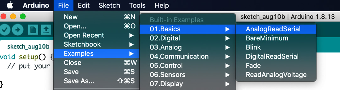
Figure 7.10 – Analog serial reading example
Selecting that menu option will open the AnalogReadSerial.ino sketch:
void setup() {
Serial.begin(9600);
}
void loop() {
int sensorValue = analogRead(0);
Serial.println(sensorValue);
delay(1);
}
The previous code introduces an instruction that we have not used so far in this project, which is Serial.println(). This code displays the data in ASCII format in a console called the serial port so that it is understandable to people and it includes a line break.
By loading and executing the script, we can open the serial monitor of our Arduino IDE to see the values that our microphone is generating (in the range 0-1023). You just need to try some test claps to find out the value of the sound of your clap and use that as a more personalized threshold.
The previous code blocks sense a microphone to detect two clap sounds and turn on and off an LED. The system waits for a 30-second timeframe between each clap sound before turning on or off the LED.
Congratulations, you have now built a wireless electronic remote control!
Summary
So, what have we learned in this project? Firstly, we learned how to connect the microphone module, LED, and resistor to the STM32 Blue Pill microcontroller board, which would be controlled by the STM32 microcontroller. We then wrote a piece of code to read an analog value and analyze it in our microcontroller. Subsequently, we sent a digital signal to turn the LED on or off depending on the embedded rules in our STM32. Lastly, we physically tested the device to understand the real-life operation.
This project gives us the skills to begin to create a remote control to automate home appliances and use them according to our needs. For example, you can add a relay module and connect it to a lamp so you can turn it on and off from the comfort of where you are without the need to reach the lamp switch.
In the next chapter, we will learn how to use the serial monitor feature to analyze the outputs that our sketch generates while it is running. We will do so by building a gas sensor project with the help of the STM32 microcontroller.
Further reading
- Colon, A. (2020). The Best Smart Home Devices for 2020. PCMAG: https://www.pcmag.com/news/the-best-smart-home-devices-for-2020
- Fox, A. (2020). The Complete Guide to Electret Condenser Microphones. My New Microphone: https://mynewmicrophone.com/the-complete-guide-to-electret-condenser-microphones/