
Chapter 9: IoT Temperature-Logging System
In recent years, the use of the internet has increased. This same increase has allowed the internet to evolve. Now we speak of things connected to this network; devices for everyday use that were not originally designed to have connectivity. This evolution has created the concept of the Internet of Things (IoT), which is defined by Morgan in Forbes (2014) as the "interconnection to the internet of commonly used devices that can complete tasks in an automated way."
The IoT is present in practically all fields of daily life, from health to education, known as the Internet of Medical Things (IoMT) and the Internet of Educational Things (IoET), respectively.
In this chapter, you will be introduced to the world of creating IoT applications with a temperature logging application for an STM32 Blue Pill board using an ESP8266 Wi-Fi module. With this knowledge, you will be able to build projects that can connect to the internet and present their data from sources such as sensors remotely.
In this chapter, we will cover the following main topics:
- Connecting a temperature sensor to the Blue Pill board
- Coding a temperature reading system
- Learning to connect the ESP8266 module
- Coding a program to send the sensed temperature to the internet
- Connecting the STM32 Blue Pill board to the internet
By the end of this chapter, you will be able to understand the operation of one of the most popular Wi-Fi modules for creating IoT applications, the ESP8266, and also be familiar with how to connect the STM32 microcontroller card to the internet and send the data obtained from the temperature sensor.
Technical requirements
The hardware components that will be needed to develop the temperature-logging system are as follows:
- 1 solderless breadboard.
- 1 Blue Pill STM32 microcontroller board.
- 1 ST-Link/V2 electronic interface needed for uploading the compiled code to the Blue Pill board. Bear in mind that the ST-Link/V2 requires 4 female to female jumper wires.
- 1 DS18B20 temperature sensor module.
- 1 ESP8266 Wi-Fi module.
- 1 FTDI adapter board.
- 1 LED.
- 1 220 ohm resistor.
- 7 male to male jumper wires.
- 5 female to female jumper wires.
- A 5 V power source.
As usual, these components are very common, and there will be no problems in obtaining them. On the software side, you will require the Arduino IDE and the GitHub repository for this chapter: https://github.com/PacktPublishing/DIY-Microcontroller-Projects-for-Hobbyists/tree/master/Chapter09
The Code in Action video for this chapter can be found here: https://bit.ly/3vSwPSu
The following section presents an introduction to the temperature sensor module and its main features.
Connecting a temperature sensor to the Blue Pill board
In this section, we are going to learn the hardware components needed to build a temperature-logging sensor using the STM32 Blue Pill and a temperature module.
To build an electronic device that measures temperature, you will need a sensor that monitors the environment and records temperature data. A microcontroller card is also necessary to be able to read the data from the sensor and to be able to display the information to users. We will begin by having a look at the temperature sensor module.
Introducing the DS18B20 temperature sensor module
Let's get to know the main hardware component's details to build the temperature log: the DS18B20 sensor. It is a digital temperature sensor that can measure air temperature, liquids (using a waterproof version), and soil.
Important note
The DS18B20 temperature sensor has a unique 64-bit serial code, allowing multiple sensors to be connected using just one digital pin (1-wire protocol) from the STM32 microcontroller card.
We will use a generic breakout module that already includes a voltage LED and the required 4.7 kΩ pull-up resistor (as shown in Figure 9.1):

Figure 9.1 – DS18B20 digital temperature sensor breakout board
It is a one-wire sensor, which means the sensor requires only one pin port for communication with the controller. Temperature is measured in degrees Celsius from –55 °C to +125 °C with an accuracy of +/-0.5 °C (between -10 °C and 85 °C). The main advantage of using this sensor instead of a thermally sensitive resistor (thermistor) is that we receive from the sensor a stream of bits on a digital pin instead of receiving voltage on an analog pin.
Now that we know about the temperature sensor, let's move on to the following subsection to connect it to the STM32 Blue Pill on the solderless breadboard.
Connecting the components
We will connect the electronic components to the solderless breadboard, do the wiring, and finally connect everything to the STM32 Blue Pill. The following are the steps to be performed:
- Place the temperature sensor and the STM32 Blue Pill on a solderless breadboard with enough space to add the wiring layer, as shown in Figure 9.2:
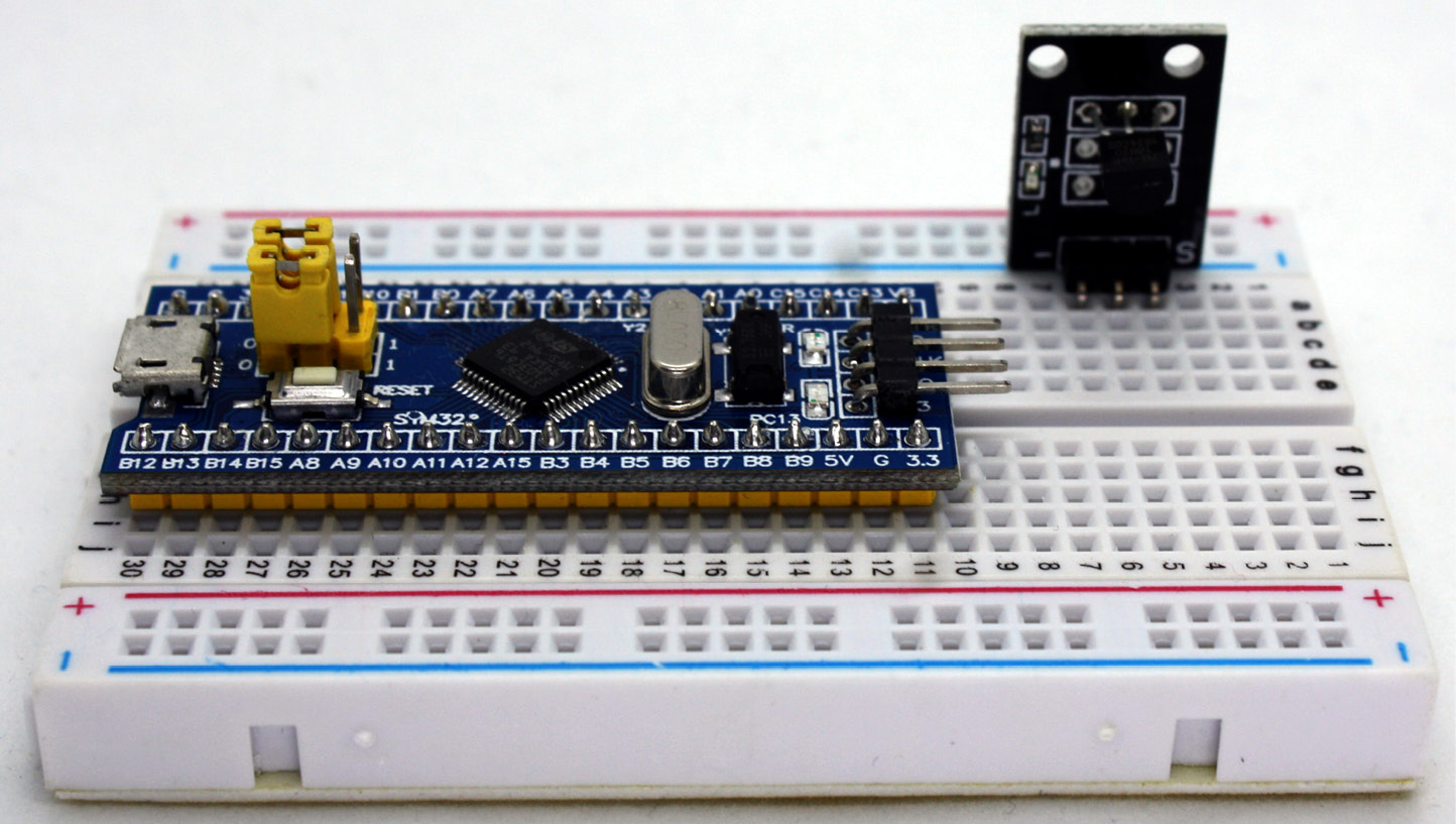
Figure 9.2 – Components on the breadboard
- Next, we will power up the temperature-logging system with an external power source. To do this, connect the STM32 Blue Pill's 5 V pin to the red rail on the solderless breadboard and a ground pin to the blue track, as shown in the following photo (Figure 9.3):

Figure 9.3 – Connections to the power supply
- Connect the ground (GND) pin of the sensor to the blue rail of the solderless breadboard or a GND terminal of the STM32 Blue Pill. Next, you need to connect the voltage (VCC) pin to the red rail of the solderless breadboard, or the 5 V bus of the STM32 Blue Pill, as shown in the following photo. The temperature sensor generates a digital output, so it must be connected to a digital input on the STM32 Blue Pill card. Connect the signal pin (S) of the temperature sensor to pin B12 of the Blue Pill, as shown in Figure 9.4:

Figure 9.4 – Temperature sensor connection to the Blue Pill
- Finally, you need to use a power source such as batteries or the STLink connected to the USB port of the computer to power up the board. As usual, we will use the STLink to upload the scripts to the microcontroller board. Figure 9.5 summarizes all the hardware connections:
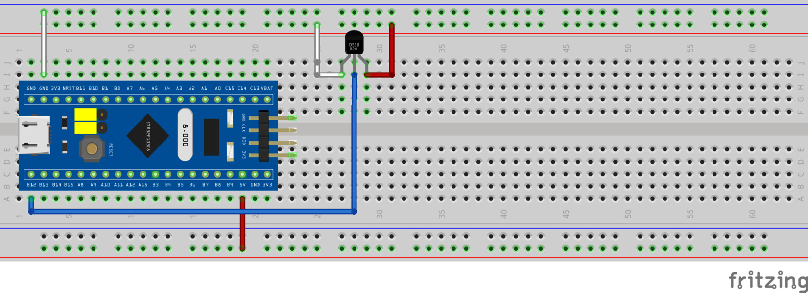
Figure 9.5 – Circuit for the temperature sensor connection
The previous diagram shows all the connections between the STM32 Blue Pill and the electronic components and summarizes the connection steps we just completed.
Figure 9.6 presents the schematics for this project:

Figure 9.6 – Schematics for the temperature sensor connection
The schematics diagram shows the electric diagram for the complete project. Figure 9.7 shows how everything is connected in our temperature-logging system:
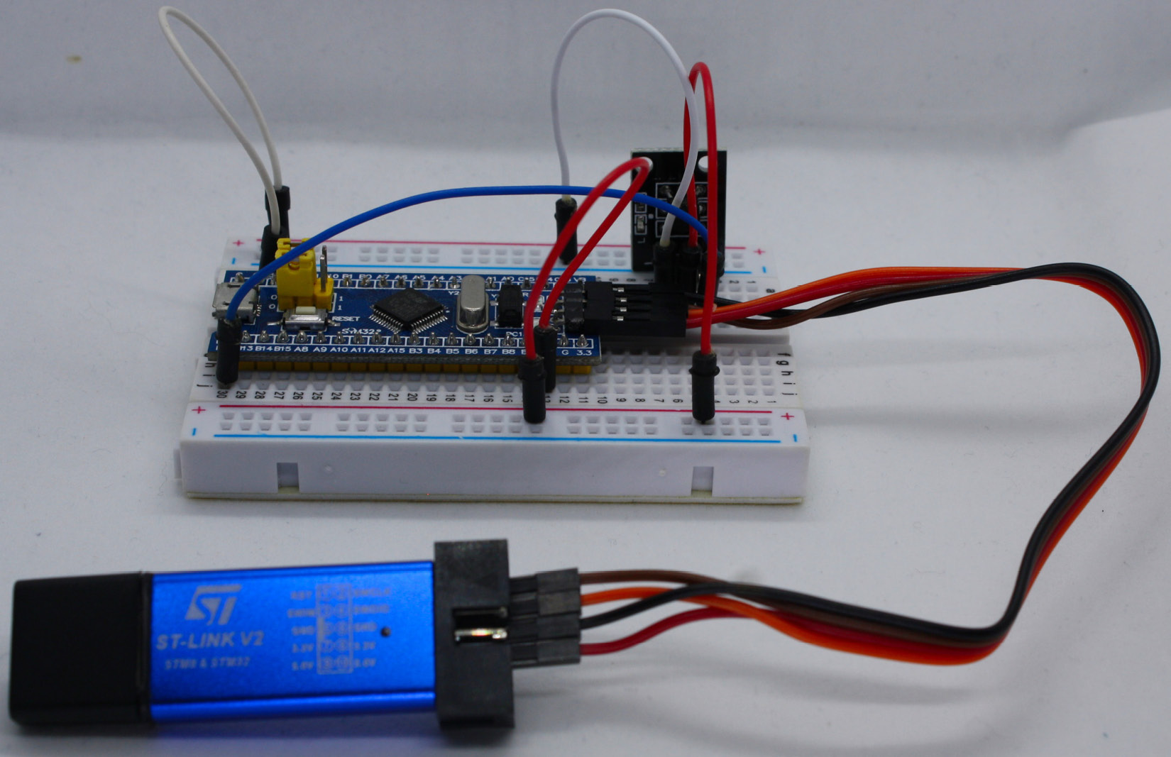
Figure 9.7 – Temperature-logging system
This section introduced you to the DS18B20 temperature sensor. We discovered its specifications and advantages versus other kinds of sensors for measuring temperature. Then you learned how to wire it on the breadboard to the interface with the STM32 Blue Pill.
It is now time to move on to the next section, which will present the C code to complete the first functionality of the IoT temperature logging.
Coding a temperature reading system
In this section, we will develop the program to take temperature readers from a sensor. As mentioned, the DS18B20 sensor works with the 1-wire protocol, so we will use the Arduino IDE libraries to program it. Let's get started:
- As the first step, we are going to install the OneWire library. Open the Arduino IDE, and then go to the Tools menu and then Manage Libraries (see Figure 9.8):

Figure 9.8 – Library manager
- Next, we will search the library by entering the word OneWire in the search box. We will install the one created by the 1-wire protocol developers, so please install the one from Jim Studt and his colleagues (see Figure 9.9):

Figure 9.9 – Installing the OneWire library
- Next, we are going to add the Dallas Temperature library. For this, we enter ds18b20 in the search box and install the library developed by Miles Burton and collaborators (see Figure 9.10). This library is also available from the sensor producers, Dallas Semiconductor (now Maxim):
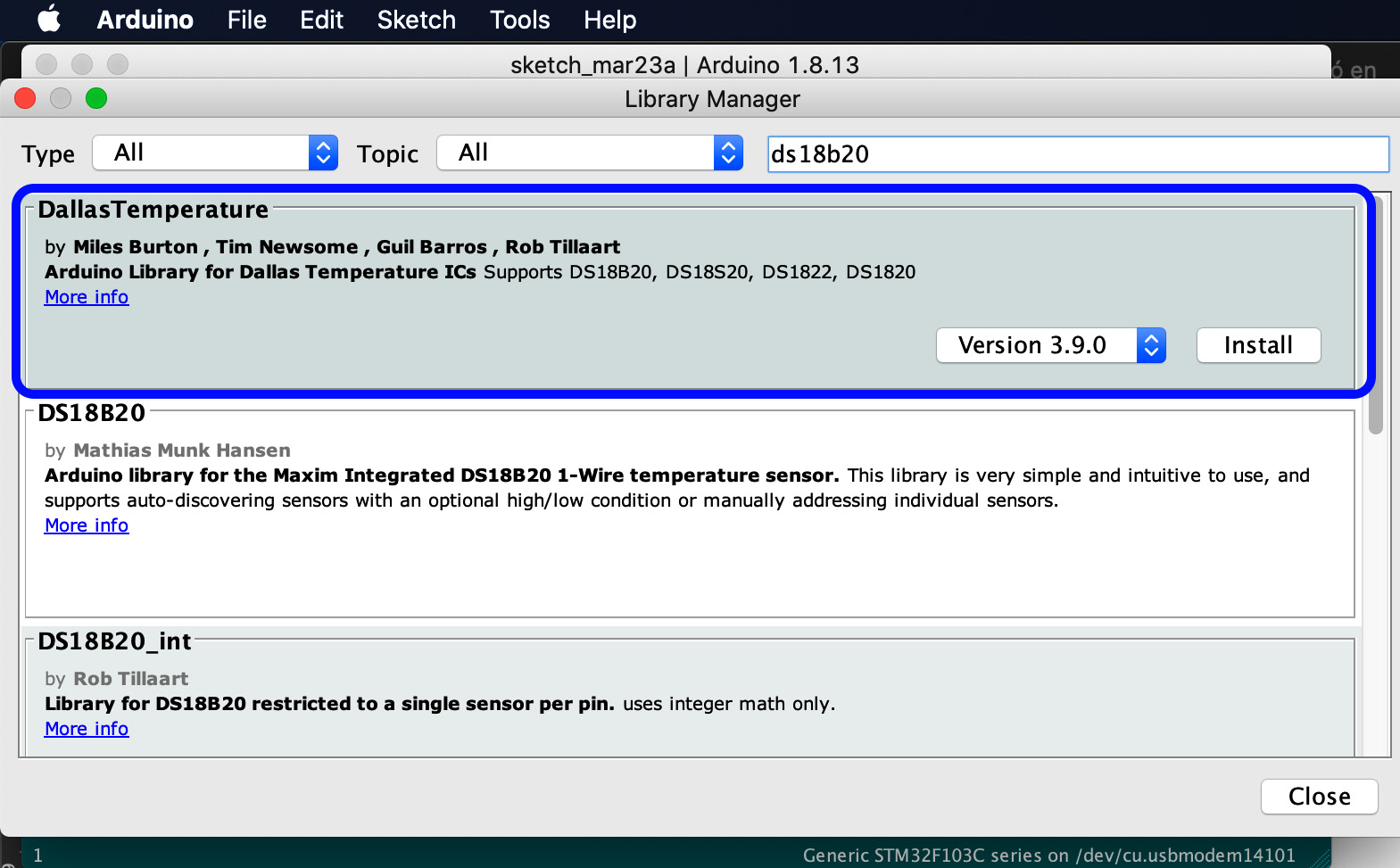
Figure 9.10 – Installing the Dallas Temperature library
Another way to install the libraries without using the built-in function of the Arduino IDE is to download the libraries from their repositories on GitHub manually. After downloading, please place them in the Arduino/Libraries folder. Next, find the repositories for the libraries at the following links.
OneWire: https://github.com/PaulStoffregen/OneWire.
Maxim (former Dallas) Temperature: https://github.com/milesburton/Arduino-Temperature-Control-Library.
- Let's write the code. We need to include the previously installed libraries and define which pin of the STM32 Blue Pill card pins will be used for input:
#include <DallasTemperature.h>
#define PIN_1_WIRE PB12
OneWire pinWire(PIN_1_WIRE);
DallasTemperature sensors(&pinWire);
As you can see in the preceding snippet, the One Wire Bus will be PB12 (labeled P12 on the Blue Pill). Also, an instance has been created to carry out the communication, and the instance's reference is passed to the temperature sensor.
- Next, in the setup() part, we need to start the serial data transmission and assign the speed of the transfer (as usual, we will use 9,600 bps as the standard value):
void setup() {
Serial.begin(9600);
}
- We also need to start reading the sensor:
void setup() {
Serial.begin(9600);
sensors.begin();
}
- Now comes the loop() part in the sketch. The requestTemperatures() function reads the value of the temperature sensor after reading the value shown on the console:
void loop() {
sensors.requestTemperatures();
int temp = sensors.getTempCByIndex(0);
Serial.print("Temperature = ");
Serial.print(temp);
Serial.println(" °C");
delay(1000);
}
Important note
If the DS18B20 temperature sensor's read value is -127, this means that something is not well connected. Verify all the wiring. Perhaps the pin connections are wrong or it is simply a case of slack cables.
We have the complete code for reading the temperature. Next, we can see the complete sketch, available in the Chapter9/temperature_reading folder in the GitHub repository.
Now that the sketch is complete, you can upload it to the Blue Pill Board. You can see in the Serial monitor the temperature that the sensor is measuring (as shown in Figure 9.11):
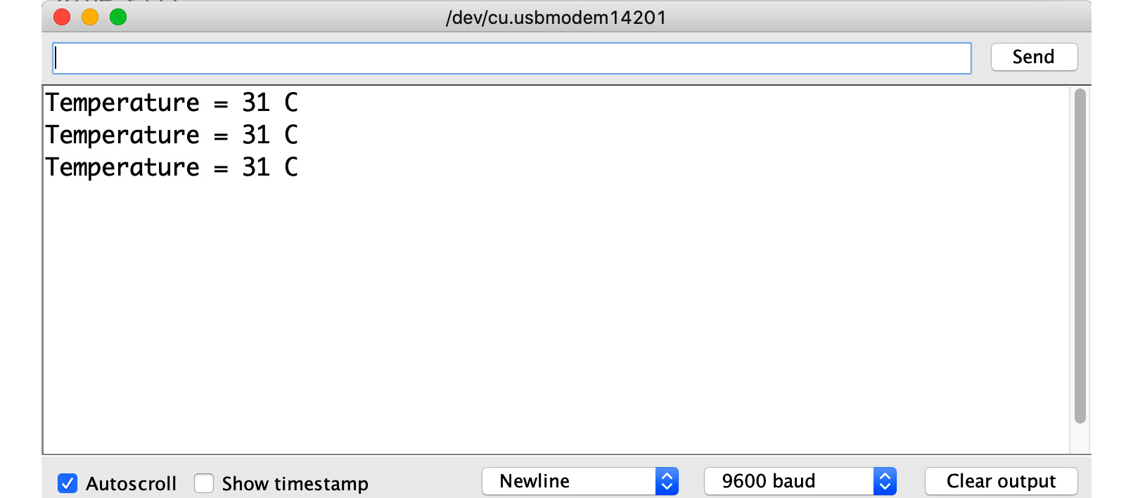
Figure 9.11 – Serial monitor temperature readings
So far, we have learned to measure the environment temperature from a sensor. During the main loop, the device keeps sensing the sensor and displays its data gathered on the serial monitor.
Next, we are ready to learn about the ESP8266 sensor module and how to connect it to load the required scripts for internet connection
Learning to connect the ESP8266 module
As we learned at the beginning of the chapter, an electronic device to be considered an IoT device must have an internet connection and make its data available through this medium.
Due to the aforementioned requirement, we will use a module that will give our temperature-logging system the ability to connect to the internet. This component is the ESP8266 Wi-Fi module.
Now, we are going to learn the hardware components needed to connect the STM32 Blue Pill to the internet using the ESP8266 Wi-Fi module. The first thing will be to know and understand the Wi-Fi module.
An introduction to the ESP8266 Wi-Fi module
The ESP8266 is a microcontroller with integrated Wi-Fi communication, and its main advantage is its very low cost compared to other chips with similar characteristics. By itself, it can work as a microcontroller, such as Arduino or Blue Pill, but it is widely used as a Wi-Fi module for other microcontrollers that do not have a built-in internet connection. This project will use it as the main microcontroller to manage the internet connection and temperature measurement. After the ESP8266 receives a remote interaction from the internet, it will connect to the STM32 Blue Pill to demonstrate the connection between both microcontrollers.
This chapter will use the ESP-01 module, which includes in a breakout board the ESP8266 chip, Wi-Fi antenna, flash memory, LEDs, and pins to connect to solderless breadboards without the need for soldering (as shown in Figure 9.12), just with a few jumper wires:

Figure 9.12 – ESP-01 breakout board with an ESP8266 Wi-Fi
The ESP-01 enables Wi-Fi communication using the TCP/IP stack over the serial port using AT commands by default from the factory.
The ESP8266 module has three types of operation:
- Station (STA).
- Access Point (AP).
- Both.
- In AP mode, the module acts as an access point on a Wi-Fi network to connect other IoT devices. In the STA type, our modules can be connected to a Wi-Fi access point of a network. The latter mode allows the SP-01 to operate as AP and STA. In this chapter, we will override the AT firmware of the SP-01 to use firmware coded by ourselves as a C script.
With a knowledge of basic features composing the ESP8266, including the ESP-01 module, let's move on to the following subsection to learn how to connect it to the STM32 Blue Pill.
Connecting an ESP8266 Wi-Fi module
In this subsection, we will learn to interface the ESP-01 for uploading our C scripts. In the end, we will have an electronic device with the ability to connect to a Wi-Fi network.
One of the most critical issues when prototyping with the SP-01 is that the pins are not physically compatible with a solderless breadboard, so we will need jumper cables to accomplish the connections.
The pin configuration of the SP-01 is as follows:
- GND corresponds to the ground.
- GPIO2 general-purpose input-output. It is digital pin number 2.
- GPIO0 general-purpose input-output. It is digital pin number 0.
- RXD is the pin where the serial port data will be received. It works at 3.3 V. It can also be used as a GPIO digital pin. This will be number 3.
- TXD is the pin where the serial port data will be transmitted. It works at 3.3 V. It can also be used as a GPIO digital pin. This will be number 1.
- CH_PD is the pin to turn the ESP-01 on and off. If we set it to 0 V (LOW), it turns off, and it turns on at 3.3 V (HIGH).
- RESET is the pin to reset the ESP-01. If we set it to 0 V (LOW), it resets. VCC is where we feed the ESP-01. It operates at 3.3 V and supports a maximum of 3.6 V. The current supplied must be greater than 200 mA.
As you can see, the SP-01 does not have analog pins, but it does have four digital pins available to work with: GPIO0, GPIO2, RXD (GPIO3), and TXD (GPIO1). To program the SP-01, we require a USB-Serial adapter (also called FTDI or TTL) and, at the same time, we can power it.
Figure 9.13 shows the connections between the SP-01 and the FTDI adapter:

Figure 9.13 – An ESP8266 connected to the Blue Pill
The following are the steps for connecting the ESP8266 to the FTDI, according to the previous diagram:
- Connect the ESP8266's RXD pin to the FTDI's TXD pin.
- Connect the ESP8266's TXD pin to the FTDI's RXD pin.
- Connect the ESP8266's GND pin to the FTDI's GND pin.
- Connect the ESP8266's CH_PD pin to the FTDI's 3.3 V pin.
- Connect the ESP8266's 3.3 V pin to the FTDI's 3.3 V pin.
To complete steps 4 and 5, you will need a solderless breadboard. Figure 9.14 shows what the connection between the FTDI and ESP-01 module looks like after everything was connected:

Figure 9.14 – Wi-Fi module connections
Important note
To load a program in the ESP-01, we must have the GPIO0 pin at a low level (LOW = GND) and the GPIO2 pin at a high level (HIGH = VCC). We must remember that the ESP8266 works with 3.3 V logic levels, so the GPIO2 pin is HIGH by default since it has an internal pull-up. Therefore, it can be left disconnected.
Finally, Figure 9.15 shows how all the finished hardware connections appear, including the temperature sensor:

Figure 9.15 – IoT temperature-logging system
Recapping what we have learned in the chapter, we now know how to obtain the ambient temperature using the DS18B20 temperature sensor and the STM32 microcontroller. We met the Wi-Fi module SP-01 and interfaced with an FTDI adapter to program and power it.
It is time to go to the next section, which will present the C code to connect the temperature sensor to the internet using the SP-01.
Coding a program to send the sensed temperature to the internet
Now, we need to develop the software for connecting the temperature sensor to the internet using the ESP8266 Wi-Fi module. Let's begin:
- Open the Arduino menu and select Preferences.
- Add https://arduino.esp8266.com/stable/package_esp8266com_index.json to the Additional Boards Manager URLs field. You will need to separate the text with a comma from the link of the STM32 module that we installed in the first chapters.
- Install the esp8266 platform. Go to the Tools menu and select Board followed by Boards Manager (see Figure 9.16):

Figure 9.16 – Installing the esp8266 platform
- Including the libraries will be the first step in the code:
#include <DallasTemperature.h>
#include <ESP8266WiFi.h>
#include <ESP8266WebServer.h>
- setup() will contain all the programming logic. We need to start the serial data transmission and assign the speed of the transfer (this time we will use 115,200 bps). At the same time, we will initialize the sensor readings:
void setup() {
Serial.begin(115200);
sensors.begin();
}
- Next, we are going to add the Wi-Fi credentials and start a web server. When the server receives a request to read, this will call a function named read_sensor:
void setup() {
Serial.begin(115200);
sensors.begin();
WiFi.softAP(ssid, password);
Serial.print("Connected, IP address: ");
Serial.println(WiFi.localIP());
server.on("/", [](){
Serial.println("Incomming connection to server");
server.send(200, "text/html", strFrm);
});
server.on("/read", read_sensor);
server.begin();;
}
- When the web server starts, an HTML button will be displayed as a command from the user to read the temperature from the sensor.
String strFrm = "<form action='read'><input type='submit' value='Read sensor'></form>";
- Finally, after the user presses the button, the server will execute the read_sensor() function. This function will read the sensor value and display it to the user over the internet:
void read_sensor() {
Serial.print("Reading the sensor: ");
sensors.requestTemperatures();
int temp = sensors.getTempCByIndex(0);
Serial.println(temp);
server.send(200, "text/plain", String("Temperature: ") + String(temp));
}
- The loop() part in the sketch will keep the internet connection waiting for the user commands:
void loop(void) {
server.handleClient();
}
Now, you can upload it to the ESP8266. To test the program, just open any web browser and open the IP assigned to our device. Figure 9.17 shows the temperature reading over the internet using the ESP8266 Wi-Fi module:
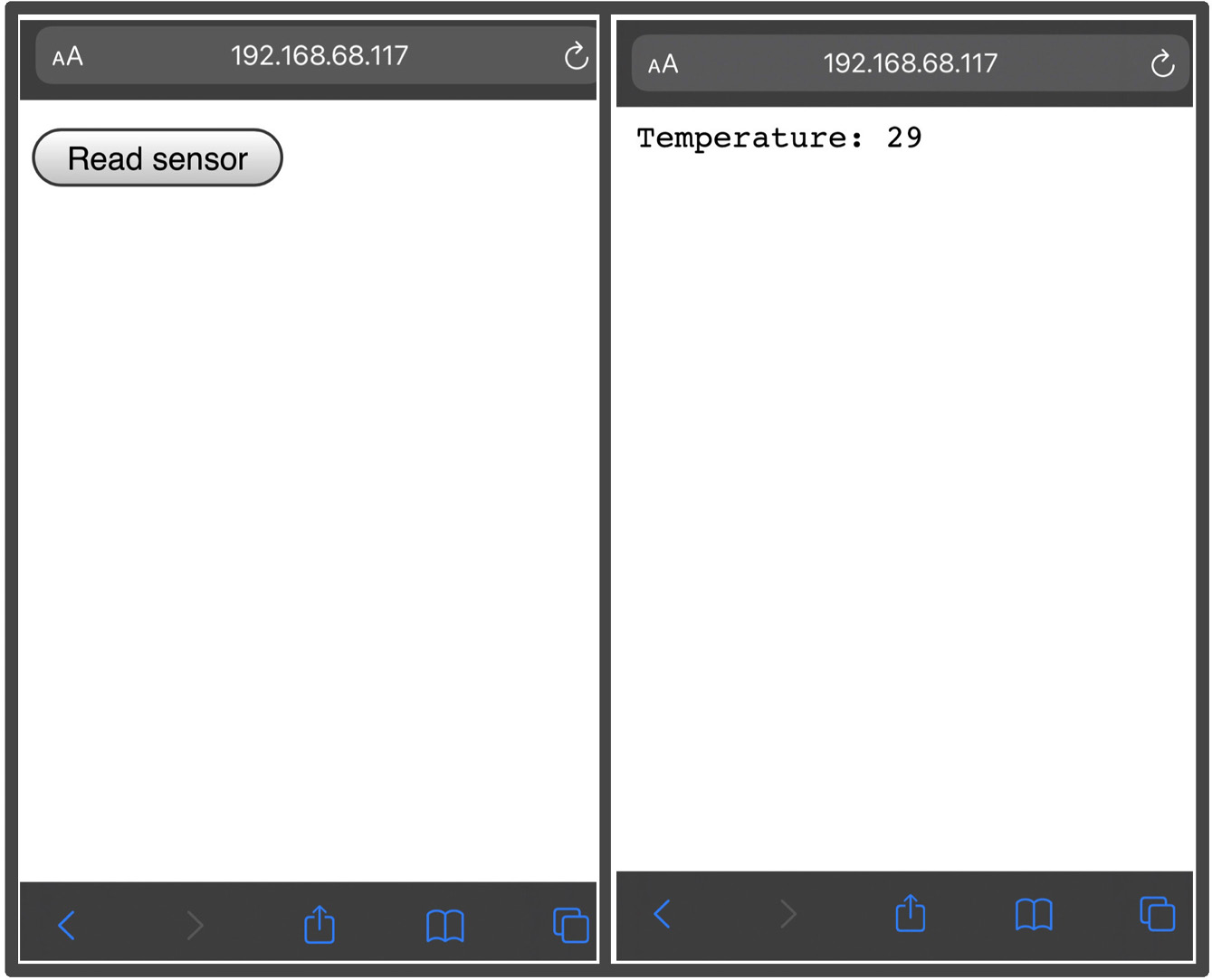
Figure 9.17 – Reading a temperature sensor over the internet
This time, we have the complete code for connecting the temperature sensor to the internet. We can find the complete sketch in the Chapter9/wifi folder in the GitHub repository.
We will make the first approach for the STM32 Blue Pill microcontroller to obtain data from the internet in the next section.
Connecting the STM32 Blue Pill board to the internet
The previous code snippets sense a sensor to measure the temperature and send the sensed data to the internet.
When the user requests the temperature from the web browser, the STM32 microcontroller will receive a request to blink an LED and consequently link it to our IoT environment created with the ESP8266 Wi-Fi module.
Figure 9.18 shows the connections required to interface the STM32 and the SP-01:
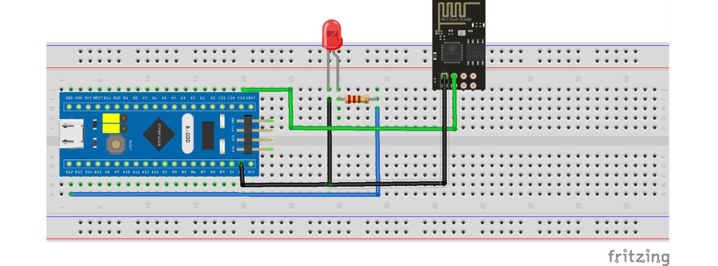
Figure 9.18 – Connecting the STM32 to the internet
Figure 9.19 shows the actual device connections between the STM32 and the SP-01:
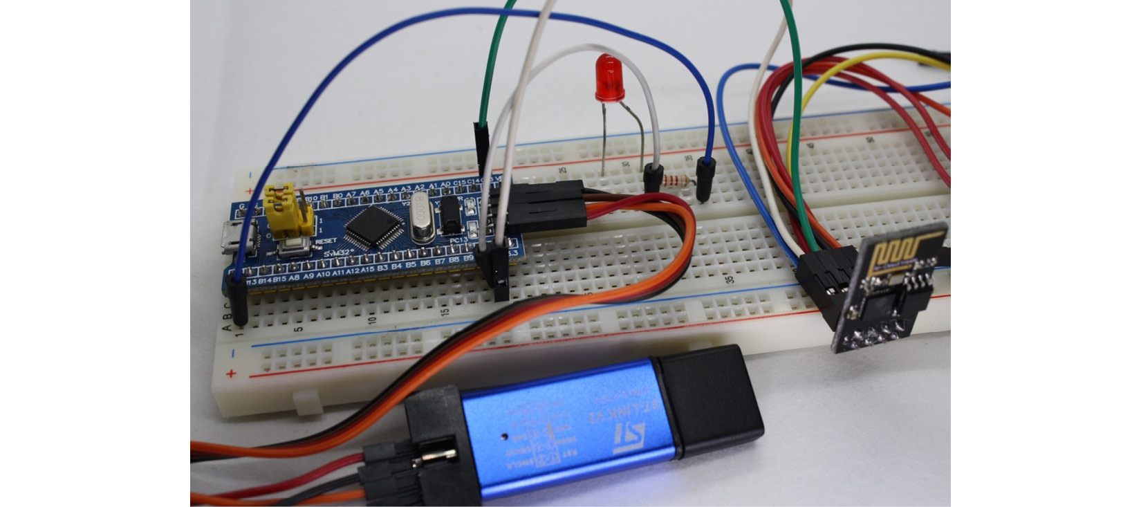
Figure 9.19 – Physical connections between the STM32 and SP-01
To complete the connection between the STM32 and the SP-01, we need to add a few lines of code to the Chapter09/wifi script:
const int toInternetPin = 0;
In the preceding line, add a constant to store the input pin used to receive the data from the internet. Then, in the read_sensor() function, add the following line to send the value 1 (HIGH) each time the user ask for the temperature:
digitalWrite(toInternetPin, HIGH);
To finish, upload the Chapter09/internetblink script to the STM32 Blue Pill microcontroller in order to read a digital input and send a digital output to blink a LED. This script will not be explained here because it uses a set of instructions that are well-known to the reader.
Open a web browser and go to the IP address of our server and press the Read sensor button. You will see the temperature and the LED blinking.
Congratulations! You have finished learning how to connect a temperature sensor to the internet using the ESP8266 Wi-Fi module ESP-01 and how to open a connection between the STM32 Blue Pill and an internet request.
Summary
What have we learned in this project? Firstly, we learned how to connect a temperature sensor to the STM32 Blue Pill microcontroller board. We then wrote the code to read the temperature and send it to our microcontroller. Subsequently, we learned how to connect a Wi-Fi module to our STM32 and code a sketch to connect the board to the internet.
This project has given us the skills to begin to create an IoT application, a great skill in this hyper-connected world. In the forthcoming chapters, you will be able to apply what you have learned since they consist of projects that require an internet connection. In Chapter 10, IoT Plant Pot Moisture Sensor, you will learn about measuring the moisture of a pot through a sensor and sending it to the cloud. We will visualize the sensor data on a web page.
Further reading
- Morgan, J. A Simple Explanation of "The Internet of Things". Forbes. 2014: https://www.forbes.com/sites/jacobmorgan/2014/05/13/simple-explanation-internet-things-that-anyone-can-understand/