
Chapter 11: IoT Solar Energy (Voltage) Measurement
Solar energy is considered one of the most promising renewable energy sources in the face of global warming challenges. It has been considered one of the best alternatives to reduce the dependency on fossil fuels and meet the growing demand for electricity (Ryan, 2005). To achieve this, sunlight is converted into electricity, and the sunlight is collected through solar panels.
In this chapter, you will continue creating IoT software for the STM32 Blue Pill microcontroller board using a voltage sensor to measure the solar energy collected by a solar panel. The application will send the sensed data to the internet using the NodeMCU ESP8266 microcontroller board.
In this chapter, we will cover the following main topics:
- Connecting a solar panel to the Blue Pill board
- Reading data from a voltage sensor module
- Coding a program to send the sensed data to the internet
- Showing sensor data results over the internet
After this chapter, you will have solid skills for developing IoT applications and improving your portfolio because it is a core element in Industry 4.0. The first skill you will learn is reading the solar panel voltage from a sensor connected to the STM32 Blue Pill. Furthermore, you will learn how to send the information read to the internet over the NodeMCU 8266 development board. Finally, you will find out how to visualize sensor values on a mobile IoT application.
Technical requirements
The hardware components that will be needed to develop the solar energy measurement system are as follows:
- One solderless breadboard.
- One Blue Pill microcontroller board.
- One NodeMCU microcontroller.
- One ST-Link/V2 electronic interface for uploading the compiled code to the Blue Pill board. Bear in mind that the ST-Link/V2 requires four female-to-female jumper wires.
- One B25 voltage sensor.
- One solar panel.
- Male-to-male jumper wires.
- Female-to-male jumper wires.
- Power source.
All the components can easily be found at your preferred electronics supplier. Remember, you will require the Arduino IDE and the GitHub repository for this chapter: https://github.com/PacktPublishing/DIY-Microcontroller-Projects-for-Hobbyists/tree/master/Chapter11
The Code in Action video for this chapter can be found here: https://bit.ly/2U4YMsT
The next section presents an introduction to the solar panels and the B25 voltage measurement sensor and how to interface them to the STM32 Blue Pill microcontroller board.
Connecting a solar panel to the Blue Pill board
Firstly, we need to learn about two components: the solar panel and the voltage measurement sensor. After learning the basics, we can build our solar energy measurement system.
Introducing the solar panel
Sunlight carries energy. When sunlight collides with a semiconductor, some energy is changed into moving electrons, generating current. Solar cells (also known as photovoltaic panels or PV panels) were created to take advantage of all the sunlight that reaches our planet. When sunlight reflects off a PV panel, the current output is constant; this is known as direct current (DC) electricity. This DC can be used to charge batteries and power microcontrollers such as the STM32 Blue Pill.
The following screenshot shows a solar panel for use with electronic components, such as our solar energy demonstration system:

Figure 11.1 – Solar panel
To facilitate the connection and operation with this solar panel, we will solder a pin header to the panel so we can directly connect jumper wires to it. The following figure shows the pin header and how the PV panel looks after being soldered:

Figure 11.2 – Soldering of pin header to the solar panel
You can also find solar panels on the market that already have integrated cables to facilitate their use, such as the one shown in the following figure:
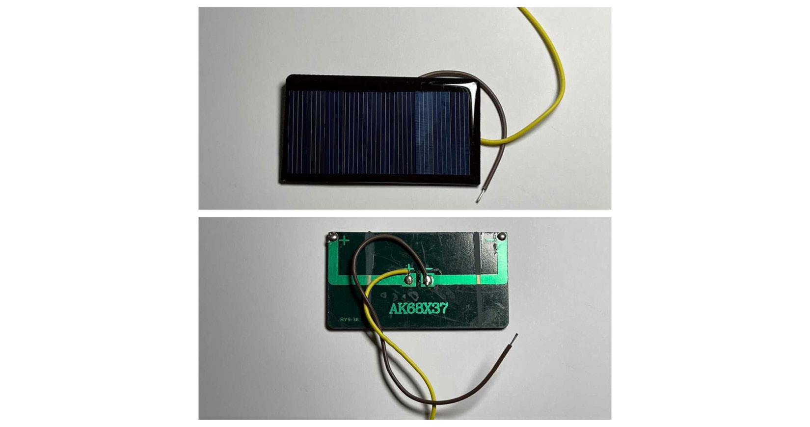
Figure 11.3 – Solar panel with integrated wires
With the knowledge of what a solar panel looks like and its functionality, let's move on to the following subsection, where we will explore the sensor we will use to measure voltage.
The B25 voltage sensor
If we need to measure voltage, we can use the analog inputs of our STM32 Blue Pill board.These inputs have a limit of 5V, so if it is necessary to measure higher voltages, it is necessary to use an external sensor to do it. The B25 sensor (see Figure 11.4) measures voltages in the 5V to 25V range, making it a very popular sensor for this task:
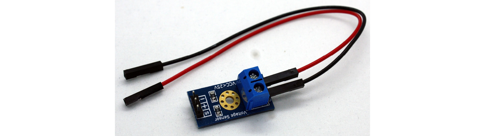
Figure 11.4 – B25 voltage sensor breakout board
As can be seen, the module has two terminals to which the external power source will be connected, one to GND and the other to VCC, which must be adjusted with a screw.
Additionally, the breakout board connects to the STM32 Blue Pill with 3 header pins. They are as follows:
- S: This pin generates an analog signal and must be connected to an analog input of the microcontroller.
- +: Not connected.
- -: Ground connection.
With this information in mind, we will learn how to connect the voltage sensor to the STM32 Blue Pill board in the next subsection.
Connecting the components
We will use a solderless breadboard to connect the sensor and the STM32 Blue Pill microcontroller and finally wire to connect the components. Here's how we wire and connect the components:
- Place the voltage sensor and the STM32 Blue Pill on the solderless breadboard. Leave some empty space to add the wires.
- Connect the ground (GND) pin of the sensor to a GND terminal of the STM32 Blue Pill.
- Next, you need to connect the sensor analog output to an analog input on the STM32 Blue Pill card and connect the S of the sensor to pin A0 of the Blue Pill, as shown in Figure 11.5:
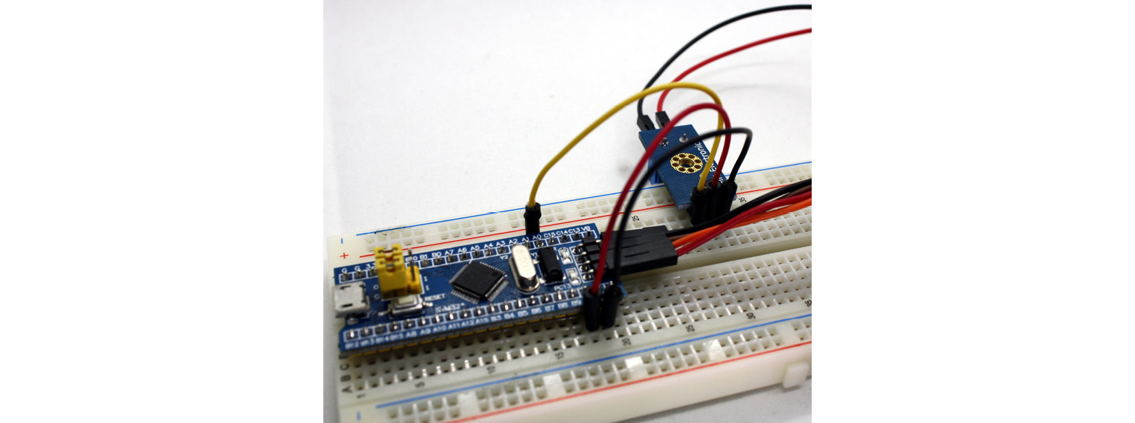
Figure 11.5 – Voltage sensor connection to the Blue Pill
- Finally, you will need a power connection to connect the solar panel to the board. Use the STLink to upload the scripts to the STM32 Blue Pill microcontroller board. Figure 11.6 summarizes all the hardware connections:
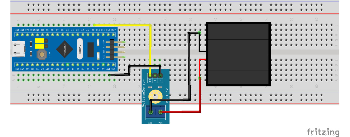
Figure 11.6: Circuit for voltage sensor connection
The following screenshot presents the schematics for this project:

Figure 11.7 – Schematics for voltage sensor connection
The schematics diagram shows the electrical connections. The VCC and ground terminals of the PV panel were connected to the VCC and GND pins of the sensor. To interface the Blue Pill with the sensor, its ground pin was connected to the GND bus of the Blue Pill, and finally, the analog output (S) of the sensor was plugged into the pin A0 of the STM32 microcontroller. Figure 11.8 shows the solar energy measurement system:

Figure 11.8 – Solar energy measurement system
Now that we have finished connecting the components, we have created a simple circuit for our voltage measurement system, as observed in the previous figure.
In this section, we learned about solar panels and met a voltage sensor and its components. We also learned how to connect the solar cell to the voltage sensor and the voltage sensor to the STM32 Blue Pill.
It is time to move on to the next section, which will show you how to write C code to complete our IoT solar energy monitoring system's first functionality.
Reading data from a voltage sensor module
It is time to learn how to code a program that will read the information from the voltage sensor and display its reading on the serial monitor.
Let's write the program to receive the sensor data from the STM32 Blue Pill:
- Declare which pin of the STM32 Blue Pill card will be used as input of the sensor data:
const int sensorPin = 0;
The input pin will be the 0 (labeled A0 on the Blue Pill).
- Next, in the setup() part, start the serial data transmission and assign the speed of the transfer to 9600 bps, and indicate to the microcontroller the type of pin assigned to A0:
void setup() {
Serial.begin(9600);
pinMode(sensorPin, INPUT);
}
- Now, in loop(), first read the input pin's data sensor, send its value to the serial port, and wait for a second:
void loop() {
int sensorValue = analogRead(sensorPin);
Serial.print("Voltage: ");
Serial.println(sensorValue);
delay(1000);
}
- We are going to load the program to the STM32 board and review the serial plotter of the Arduino IDE to know the waveform of the analog signal that we are reading from the sensor, and the result can be seen in Figure 11.9:

Figure 11.9 – Sensor signal waveform in the serial plotter
The waveform that forms the sensor signal can take the values from 0 to 1023. Then, it will be necessary to convert this value to voltage.
- We will add two lines to our script to show the voltage value, and we will comment on the one that sends the signal value to the serial port:
void loop() {
int sensorValue = analogRead(sensorPin);
double voltageValue = map(sensorValue, 0, 1023, 0, 25);
Serial.print("Voltage: ");
//Serial.println(sensorValue);
Serial.println(voltageValue);
delay(1000);
}
The map() function transforms a number from one range to another:
map(value, fromLow, fromHigh, toLow, toHigh)
The first parameter that map() receives is the value to be converted. In our program, it is the value read from the sensor. The value of fromLow will be mapped to toLow, and fromHigh to toHigh, and all values within the range.
Now, upload it to the Blue Pill board. Now you can see in the serial monitor the voltage value as shown in Figure 11.10:

Figure 11.10 – Serial monitor readings
For the complete sketch, refer to the Chapter11/voltage folder in the GitHub repository.
What have we learned so far? We introduced the B25 sensor to measure voltage and know about solar panels. We learned to connect them to our STM32 Blue Pill microcontroller, write the code to read the sensor data, display it on the serial monitor, and graph it in the serial plotter.
Some new skills were acquired in this section, and these skills will help you build electronic systems that require monitoring of the voltage level.
Next, we will use the NodeMCU microcontroller to send the sensed data to the internet.
Coding a program to send the sensed data to the internet
In this section, we will continue using the NodeMCU development board to receive the data from the STM32 and send it to the internet. However, unlike Chapter 10, IoT Plant Pot Moisture Sensor, where a digital value (1 or 0) was sent directly between both microcontrollers, we now need to send the voltage value using serial communication between these microcontrollers.
Serial transmission is done by sending the data using the RX/TX pins.
Let's create the program to connect the NodeMCU and the STM32:
- In setup(), we need to add new serial data transmission to 115200 bps. It is the recommended speed for the NodeMCU board:
void setup() {
serial.begin(9600);
Serial1.begin(115200);
}
- The loop() instance needs a new line after the sensor reading and voltage conversion. The write() function sends the data as an integer value:
void loop() {
int sensorValue = analogRead(sensorPin);
double voltageValue = map(sensorValue, 0, 1023, 0, 25);
Serial.print("Voltage: ");
//Serial.println(sensorValue);
Serial.println(voltageValue);
Serial1.write((int)voltageValue);
delay(1000);
}
- To complete the communication between the NodeMCU and the STM32, it will be necessary to add the additional connections shown in Figure 11.11 and Figure 11.12:

Figure 11.11 – Circuit for microcontroller serial communication
Figure 11.12 shows the schematics diagram for the circuit interfacing between the STM32 and the NodeMCU microcontrollers:

Figure 11.12 – Schematics for microcontroller serial communication
Connect the RX pin from NodeMCU to the TX pin (B6) of the STM32 and the TX pin from NodeMCU to the RX pin (B7) of the STM32.
Figure 11.13 shows how everything was connected in the actual system, including the voltage sensor:

Figure 11.13 – STM32 and NodeMCU serial connection
- Now, to complete the serial connection between the NodeMCU and the STM32, we will create a new sketch, Chapter11/voltage_iot.
- In setup(), indicate the serial data transmission:
void setup() {
Serial.begin(115200);
}
- The final step is loop():
void loop() {
double data = Serial.read();
Serial.print("Voltage: ");
Serial.println(data);
delay(1000);
}
With the preceding code, the NodeMCU will receive the sensor value from the STM32 and will display it on the serial monitor.
The sketch is now complete. Upload it to the NodeMCU board, and reset it after completing the upload. Now you can see, in the serial monitor, the sensor value, as shown in the following screenshot:
It is now time to move on to the next section, which will show you how to visualize data over the internet.
Showing sensor data results over the internet
In Chapter 9, IoT Temperature-Logging System, and Chapter 10, IoT Plant Pot Moisture Sensor, we learned how to program IoT applications within our local network. In this section of the chapter, we will learn how to send data to the cloud outside of our local network.
A wide variety of cloud platforms allow us to connect our IoT devices to their services. Most allow us to use essential services at no cost. If something more complete is desired, there is a charge, generally a monthly payment. This time we will use the Blynk platform, which has several free options, and they are the ones we will use.
Blynk has an app for both Android and iOS that will allow us to monitor the value of the voltage in our solar cell.
Let's look at the steps to send and view our information from the internet with a mobile app:
- Download the Blynk app.
For Android, download it from https://play.google.com/store/apps/details?id=cc.blynk&hl=en_US.
For iOS, download it from https://apps.apple.com/us/app/blynk-iot-for-arduino-esp32/id808760481.
- Create a new account:
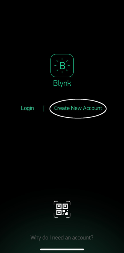
Figure 11.14 – Blynk, home screen
- Once your account is created, create a new project. Write a name, select ESP8266 as the device, and set WiFi as the connection type. Then click on Create Project:
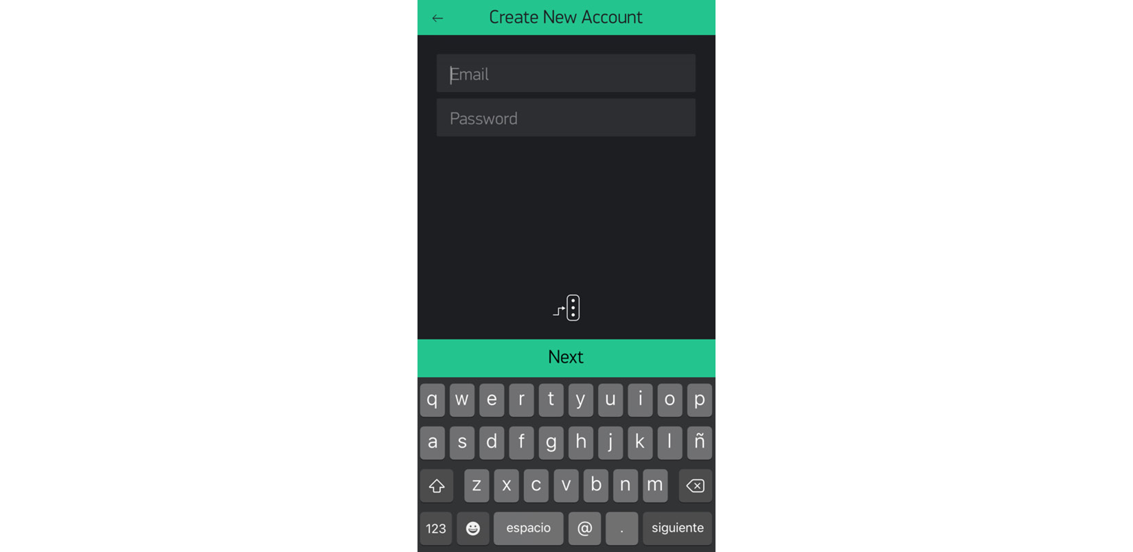
Figure 11.15 – Blynk, creating a new account
- You will receive an email with the necessary token for the app, which you can also find in Settings:

Figure 11.16 – Blynk, menu screen
- Write a name, select ESP8266 as the device, and WiFi as connection type. Click on Create Project:
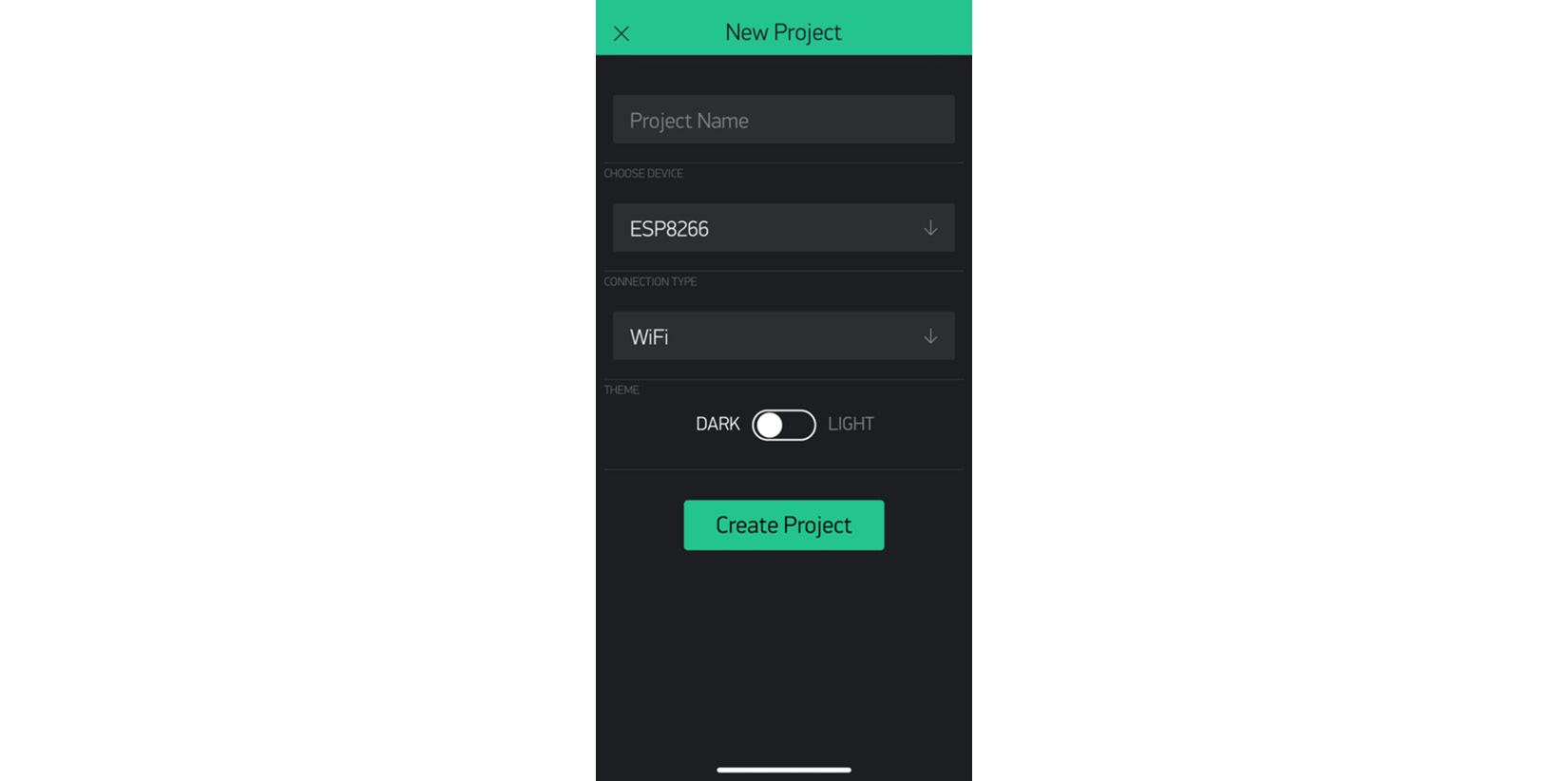
Figure 11.17 – Blynk, creating a new project
- You will receive an email with the necessary token for the app, which you can also find in Settings.
- Press the screen and the Widget toolbox will appear:
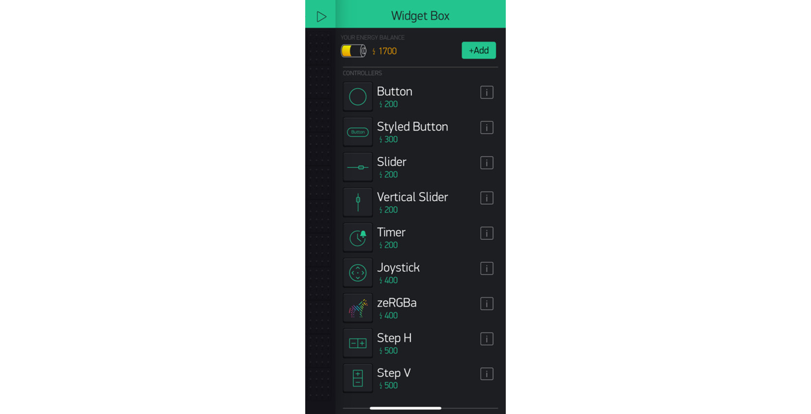
Figure 11.18 – Blynk, widgets box
- Add a Gauge component. Configure it and press the OK button:

Figure 11.19 – Solar energy app in Blynk
- Finally, upload the Chapter11/voltage_iot program to the NodeMCU and execute it.
We have reached the end of Chapter 11, IoT Solar Energy (Voltage) Measurement. Congratulations!
Summary
In this chapter dedicated to IoT, we have learned some essential topics. First, we got to know the solar cells used to power small electronic devices. Next, we learned about the B25 voltage sensor and how to connect it to the STM32.
Later, we learned how to create a program to read data from the voltage sensor. With the voltage reading, we connect our STM32 to a NodeMCU board through serial communication. We create a program to send the voltage value between microcontrollers. Finally, we use an app to visualize the sensor data from the cloud.
At the end of the IoT topics, you have solid skills to create applications and devices connected to the internet and intranets. Your portfolio of projects has been strengthened to enable you to more easily find a job opportunity in this growth area.
In the next chapter, you will start developing projects that will help you create electronic support devices to assist with the COVID-19 pandemic.
Further reading
Ryan, V., What Is Solar Energy? Technology Student, 2005: https://technologystudent.com/energy1/solar1.htm