Chapter 3: Getting Started with OpenGL and Vulkan
In this chapter, we will cover the basic steps of modern OpenGL and Vulkan. We will also learn how to deal with textures, buffers, shaders, and pipelines. The recipes in this chapter will not focus solely on the graphics APIs that are available, but on various tips and tricks that are necessary for improving graphical application development and various 3D graphics algorithms. On the Vulkan side, we will cover the basics so that we can get it up and running.
In this chapter, we will cover the following recipes:
- Intercepting OpenGL API calls
- Working with Direct State Access (DSA)
- Loading and compiling shaders in OpenGL
- Implementing programmable vertex pulling (PVP) in OpenGL
- Working with cube map textures
- Compiling Vulkan shaders at runtime
- Initializing Vulkan instances and graphical devices
- Initializing the Vulkan swap chain
- Setting up Vulkan's debugging capabilities
- Tracking and cleaning up Vulkan objects
- Using Vulkan command buffers
- Dealing with buffers in Vulkan
- Using texture data in Vulkan
- Using mesh geometry data in Vulkan
- Using Vulkan descriptor sets
- Initializing Vulkan shader modules
- Initializing the Vulkan pipeline
- Putting it all together into a Vulkan application
Technical requirements
To complete the recipes in this chapter, you must have a computer with a video card that can support OpenGL 4.6 and Vulkan 1.1. Read Chapter 1, Establishing a Build Environment, if you want to learn how to configure your computer properly.
You can find the code files present in this chapter on GitHub at https://github.com/PacktPublishing/3D-Graphics-Rendering-Cookbook/tree/master/Chapter3
Intercepting OpenGL API calls
Sometimes, it is very desirable to intercept OpenGL API calls for debugging purposes or, for example, to manipulate the underlying OpenGL state before passing API calls into the real OpenGL system. You can do this to simulate mobile OpenGL on top of a desktop OpenGL implementation or vice versa. Manually writing wrappers for each and every API function is a tedious and thankless job. In this recipe, you will learn how to quickly make custom OpenGL hooks and use them in your applications.
Getting ready
This recipe uses a Python script to parse glcorearb.h and generate all the necessary scaffolding code for the wrapper functions. The complete source code for this recipe can be found in this book's source code bundle, under the name Chapter3/GL01_APIWrapping.
How to do it...
Let's write a small OpenGL application that prints all the GL API functions that have been used, along with their parameters, in the console window while the application is running:
- First, let's run the supplementary Python script with the following command:
python GetGLAPI.py > GLAPITrace.h
This script reads input from funcs_list.txt, which contains the list of OpenGL functions that we want to wrap, in the following format:
glActiveTexture
glAttachShader
glBeginQuery
glBindAttribLocation
glBindBuffer
...
This script creates two files called GLAPI.h and GLAPITrace.h.
- Now, we can declare the GL4API struct, including the first generated file, as follows:
struct GL4API {
# include "GLAPI.h"
};
This structure contains pointers to all the required OpenGL functions.
- Next, declare a function type and two function prototypes:
using PFNGETGLPROC = void* (const char*);
void GetAPI4(GL4API* api, PFNGETGLPROC GetGLProc);
void InjectAPITracer4(GL4API* api);
Their implementations can be found in GLAPITrace.h.
Now, we can use these functions in our application.
- Define a GL4API instance, fill it with OpenGL function pointers, and inject the wrapping code. Use glfwGetProcAddress() to retrieve the pointers to OpenGL functions:
GL4API api;
GetAPI4(&api, [](const char* func) -> void*
{ return (void *)glfwGetProcAddress(func); });
InjectAPITracer4(&api);
- Invoke all subsequent OpenGL commands using the api. structure:
const GLuint shaderVertex = api.glCreateShader(GL_VERTEX_SHADER);
api.glShaderSource( shaderVertex, 1, &shaderCodeVertex, nullptr);
api.glCompileShader(shaderVertex);
...
The console output of the running program should look as follows:
glViewport(0, 0, 1024, 768)
glClear(16384)
glUseProgram(3)
glNamedBufferSubData(1, 0, 64, 000000F5508FF6B0)
glDrawArrays(GL_TRIANGLES, 0, 3)
glViewport(0, 0, 1024, 768)
glClear(16384)
glUseProgram(3)
glNamedBufferSubData(1, 0, 64, 000000F5508FF6B0)
glDrawArrays(GL_TRIANGLES, 0, 3)
This approach can be used for logging and debugging, and it can even be extended to record sequences of OpenGL commands or similar purposes. By changing the Python script, it is easy to customize the generated wrappers to your own needs.
How it works...
The first generated file, GLAPI.h, contains a list of declarations in the following form:
PFNGLACTIVETEXTUREPROC glActiveTexture;
PFNGLATTACHSHADERPROC glAttachShader;
PFNGLBEGINQUERYPROC glBeginQuery;
PFNGLBINDATTRIBLOCATIONPROC glBindAttribLocation;
PFNGLBINDBUFFERPROC glBindBuffer;
...
The second generated file, GLAPITrace.h, contains a long list of actual wrappers for every specified OpenGL function call. Each wrapper prints parameters in the console, invokes the actual function through a pointer, which, in turn, might be a wrapper as well, and checks for GL errors once the function returns. Let's take a look at a couple of functions from this file:
void GLTracer_glCullFace(GLenum mode) {
printf("glCullFace(" "%s) ", E2S(mode));
apiHook.glCullFace(mode);
assert(apiHook.glGetError() == GL_NO_ERROR);
}
void GLTracer_glPolygonMode(GLenum face, GLenum mode) {
printf( "glPolygonMode(" "%s, %s) ", E2S(face), E2S(mode));
apiHook.glPolygonMode(face, mode);
assert(apiHook.glGetError() == GL_NO_ERROR);
}
...
The Enum2String() helper function, which is used inside the wrappers via the E2S() macro, converts a GLenum value into an appropriate string representation. This is just a hardcoded list of values; there's nothing really fancy here. For values not in the list, the function will return a numerical representation of the enum via std::to_string():
#define W( en ) if ( e == en ) return #en;
std::string Enum2String(GLenum e) {
W(GL_POINTS);
W(GL_LINES);
W(GL_LINE_LOOP);
W(GL_LINE_STRIP);
W(GL_TRIANGLES);
...
return std::to_string(e);
}
Besides that, there are two more function definitions that are generated here. The first one loads OpenGL function pointers into the GL4API structure using the supplied lambda, like so:
#define LOAD_GL_FUNC(f) api->func = (decltype(api->f))GetGLProc(#f);
void GetAPI4(GL4API* api, PFNGETGLPROC GetGLProc) {
LOAD_GL_FUNC(glActiveTexture);
LOAD_GL_FUNC(glAttachShader);
LOAD_GL_FUNC(glBeginQuery);
LOAD_GL_FUNC(glBindAttribLocation);
...
The second one, called InjectAPITracer4(), is defined as follows:
#define INJECT(S) api->S = &GLTracer_##S;
void InjectAPITracer4(GL4API* api) {
apiHook = *api;
INJECT(glActiveTexture);
INJECT(glAttachShader);
INJECT(glBeginQuery);
INJECT(glBindAttribLocation);
...
This function saves the previous value of GL4API into a static global variable and replaces the function pointers with pointers to the custom wrapper functions.
Working with Direct State Access (DSA)
Starting with version 4.5, OpenGL Core Profile allows us to modify the state of objects without enforcing the bind-to-edit model that was used in previous versions of OpenGL. Let's take a closer look at the new functions that provide a straightforward, object-oriented interface and do not affect the global state.
Getting ready
The OpenGL examples provided in this book use the DSA programming model, which you were exposed to in Chapter 2, Using Essential Libraries. If you are not familiar with DSA yet, it is recommended that you go through the source code for all the applications covered in Chapter 2, Using Essential Libraries, to get a solid grasp of this approach to small, self-contained examples.
All DSA functions can be separated into the following object families:
- Texture
- Framebuffer
- Buffer
- Transform feedback
- Vertex array
- Sampler
- Query
- Program
Let's go through a couple of these object families to understand how the new API works.
How to do it...
The first family of functions is related to texture objects. Let's take a look:
- Create a set of texture objects with the following command, which specifies a texture target right from the get-go:
void glCreateTextures( GLenum target, GLsizei n, GLuint* textures);
- All texture parameters should be set directly with this group function, based on the parameter type. It is the DSA equivalent of glTexParameter...() functions:
void glTextureParameter...( GLuint texture, GLenum pname, ...);
- Using glActiveTexture() and glBindTexture() is no longer required. Instead, a single command should be used:
void glBindTextureUnit(GLuint unit, GLuint texture);
Note
Typically, we would use the following pair of functions:
glActiveTexture(GL_TEXTURE0 + 2);glBindTexture(GL_TEXTURE_2D, texId);
Instead of this, you can use the one-liner shown here. The texture target will be inferred from the texture object itself, which means using GL_TEXTURE0 is no longer required:
glBindTextureUnit(2, texId);
Alternatively, if you want to bind a few textures to a sequence of texture units at the same time, use the following command:
void glBindTextures(GLuint first, GLsizei count,
const GLuint* textures);
- Generating texture mipmaps can now be done directly. Like all the DSA functions, this one takes the OpenGL GLuint name instead of a texture target:
void glGenerateTextureMipmap(GLuint texture);
- Uploading data into textures should be done in the following way. First, we should tell OpenGL how much and what kind of storage should be allocated for a texture using one of the following functions:
void glTextureStorage...();
- The actual pixels can be uploaded, compressed, or decompressed with one of the following calls:
void glTextureSubImage...();
void glCompressedTextureSubImage...();
Let's take a look at how a 2D texture can be uploaded in one of the examples from the previous chapter; that is, Chapter2�3_STBsrcmain.cpp:
GLuint t;
glCreateTextures(GL_TEXTURE_2D, 1, &t);
glTextureParameteri(t, GL_TEXTURE_MAX_LEVEL, 0);
glTextureParameteri(t, GL_TEXTURE_MIN_FILTER, GL_LINEAR);
glTextureParameteri(t, GL_TEXTURE_MAG_FILTER, GL_LINEAR);
glTextureStorage2D(t, 1, GL_RGB8, w, h);
glTextureSubImage2D( t, 0, 0, 0, w, h, GL_RGB, GL_UNSIGNED_BYTE, img);
This API prevents many situations where a texture object might remain in an incomplete state due to a wrong sequence of legacy glTexImage...() calls.
Let's look at another family of functions related to buffers. It all starts with a call to glCreateBuffers(), which will create a set of buffers. It does not require a specific buffer target, which means that buffers can be created and reused for specific purposes later, making them completely interchangeable. For example, a shader storage buffer can be filled on a GPU via a compute shader and be reused as an indirect buffer for draw commands. We will touch on this mechanic in the subsequent chapters. For now, let's focus on how to create and set up buffer objects using the new DSA functions. Check out Chapter2�7_Assimpsrcmain.cpp for the full source code:
- A uniform buffer object can be created in the following way:
const GLsizeiptr kBufSize = sizeof(PerFrameData);
GLuint buf;
glCreateBuffers(1, &buf);
- Now, we should specify the storage for our uniform buffer. The GL_DYNAMIC_STORAGE_BIT flag tells the OpenGL implementation that the contents of the buffer may be updated later through calls to glBufferSubData():
glNamedBufferStorage( buf, kBufSize, nullptr, GL_DYNAMIC_STORAGE_BIT);
- To make the entire buffer accessible from GLSL shaders at binding point 0, we should use the following function call:
glBindBufferRange( GL_UNIFORM_BUFFER, 0, buf, 0, kBufSize);
Other types of buffers can be created in a similar fashion. We will discuss them on an as-needed basis in subsequent chapters.
There is one more important thing to mention, which is how to set up the vertex attributes format for vertex array objects (VAOs). Let's take a closer look at how to store vertex positions in vec3 format inside a buffer and render from it:
- First, we should create a buffer to store vertex data in. The flag should be set to 0 as the contents of this buffer will be immutable:
GLuint buf;
glCreateBuffers(1, &buf);
glNamedBufferStorage( buf, sizeof(vec3) * pos.size(), pos.data(), 0);
- Now, let's use this buffer to set up a vertex array object:
GLuint vao;
glCreateVertexArrays(1, &vao);
- The data for GLSL attribute stream (location) 0, which we use for vertex 3D positions, should be sourced from the buf buffer, start from an offset of 0, and use a stride equal to the size of vec3. This means that positions are tightly packed inside the buffer, without any interleaving with other data, such as normal vectors or texture coordinates:
glVertexArrayVertexBuffer( vao, 0, buf, 0, sizeof(vec3));
glEnableVertexArrayAttrib(vao, 0 );
- Now, we should describe what the format our data will be in for attribute stream number 0. Each value contains 3 components of the GL_FLOAT type. No normalization is required. The relative offset, which is the distance between the elements within a buffer, should be zero in the case of tightly packed values. Here is how to set it up:
glVertexArrayAttribFormat( vao, 0, 3, GL_FLOAT, GL_FALSE, 0);
- The following call connects a vertex buffer binding point of 0 within the vertex attribute format we described as number 0:
glVertexArrayAttribBinding(vao, 0, 0);
This might sound confusing at first, but imagine that we have one big buffer containing interleaving positions, texture coordinates, and colors, as in the Chapter2�4_ImGui example. Let's look at a complete code fragment for how this VAO should be set up:
- Create a VAO, like so:
GLuint vao;
glCreateVertexArrays(1, &vao);
- Bind a buffer containing indices to this VAO:
glVertexArrayElementBuffer(vao, handleElements);
- Bind a buffer containing the interleaved vertex data to this VAO's buffer binding point; that is, 0:
glVertexArrayVertexBuffer( vao, 0, handleVBO, 0, sizeof(ImDrawVert));
- Enable all three vertex attributes streams:
glEnableVertexArrayAttrib(vao, 0);
glEnableVertexArrayAttrib(vao, 1);
glEnableVertexArrayAttrib(vao, 2);
- Specify a data format for each attribute stream. The streams have their indices set to 0, 1, and 2, which correspond to the location binding points in the GLSL shaders:
glVertexArrayAttribFormat(vao, 0, 2, GL_FLOAT, GL_FALSE, IM_OFFSETOF(ImDrawVert, pos));
glVertexArrayAttribFormat(vao, 1, 2, GL_FLOAT, GL_FALSE, IM_OFFSETOF(ImDrawVert, uv));
glVertexArrayAttribFormat(vao, 2, 4, GL_UNSIGNED_BYTE, GL_TRUE, IM_OFFSETOF(ImDrawVert, col));
- Now, tell OpenGL to read the data for streams 0, 1, and 2 from the buffer, which is attached to buffer binding point 0:
glVertexArrayAttribBinding(vao, 0, 0);
glVertexArrayAttribBinding(vao, 1, 0);
glVertexArrayAttribBinding(vao, 2, 0);
There's more...
The VAO setup is probably the most complicated part of the new DSA API. Other objects are much simpler to set up; we will discuss how to work with them in subsequent chapters.
Loading and compiling shaders in OpenGL
In Chapter 2, Using Essential Libraries, our tiny OpenGL examples loaded all the GLSL shaders directly from the const char* variables defined inside our source code. While this approach is acceptable in the territory of 100-line demos, it does not scale well beyond that. In this recipe, we will learn how to load, compile, and link shaders and shader programs. This approach will be used throughout the rest of the examples in this book.
Getting ready
Before we can proceed with the actual shader loading, we need two graphics API-agnostic functions. The first one loads a text file as std::string:
std::string readShaderFile(const char* fileName) {
FILE* file = fopen(fileName, "r");
if (!file) {
printf("I/O error. Cannot open '%s' ", fileName);
return std::string();
}
fseek(file, 0L, SEEK_END);
const auto bytesinfile = ftell(file);
fseek(file, 0L, SEEK_SET);
char* buffer = (char*)alloca(bytesinfile + 1);
const size_t bytesread = fread( buffer, 1, bytesinfile, file);
fclose(file);
buffer[bytesread] = 0;
The important thing to mention here is that we parse and eliminate the UTF byte-order marker. If present, it might not be handled properly by some legacy GLSL compilers, especially on Android:
static constexpr unsigned char BOM[] = { 0xEF, 0xBB, 0xBF };
if (bytesread > 3)
if (!memcmp(buffer, BOM, 3)) memset(buffer, ' ', 3);
std::string code(buffer);
We should also handle #include directives inside the shader source code. This code is not robust enough to be shipped, but it is good enough for our purposes:
while (code.find("#include ") != code.npos) {
const auto pos = code.find("#include ");
const auto p1 = code.find('<', pos);
const auto p2 = code.find('>', pos);
if (p1 == code.npos || p2 == code.npos || p2 <= p1) {
printf("Error while loading shader program: %s ", code.c_str());
return std::string();
}
const std::string name = code.substr(p1 + 1, p2 - p1 – 1);
const std::string include = readShaderFile(name.c_str());
code.replace(pos, p2-pos+1, include.c_str());
}
return code;
}
The second helper function prints shader source code in the console. Each source code line is annotated with a line number, making it extremely easy to debug shader compilation using the error line number generated by the GLSL compiler's output:
static void printShaderSource(const char* text) {
int line = 1;
printf(" (%3i) ", line);
while (text && *text++) {
if (*text == ' ') printf(" (%3i) ", ++line);
else if (*text == ' ') {}
else printf("%c", *text);
}
printf(" ");
}
The source code for these functions can be found in the shared/Utils.cpp and shared/GLShader.cpp files.
How to do it...
Let's create some C++ resource acquisition is initialization (RAII) wrappers on top of our OpenGL shaders and programs:
- First, we need to convert a shader file name into an OpenGL shader type based on the file's extension:
GLenum GLShaderTypeFromFileName(const char* fileName)
{
if (endsWith(fileName, ".vert")) return GL_VERTEX_SHADER;
if (endsWith(fileName, ".frag")) return GL_FRAGMENT_SHADER;
if (endsWith(fileName, ".geom")) return GL_GEOMETRY_SHADER;
if (endsWith(fileName, ".tesc")) return GL_TESS_CONTROL_SHADER;
if (endsWith(fileName, ".tese")) return GL_TESS_EVALUATION_SHADER;
if (endsWith(fileName, ".comp")) return GL_COMPUTE_SHADER;
assert(false);
return 0;
}
- The endsWith() helper function is basically a one-liner and checks if a string ends with a specified substring:
int endsWith(const char* s, const char* part) {
return (strstr(s, part) - s) == (strlen(s) – strlen(part));
}
- The shader wrapper interface looks as follows. Constructors take either a filename or a shader type and source code as input:
class GLShader {
public:
explicit GLShader(const char* fileName);
GLShader(GLenum type, const char* text);
~GLShader();
- The shader type will be required later, once we want to link our shaders to a shader program:
GLenum getType() const { return type_; }
GLuint getHandle() const { return handle_; }
private:
GLenum type_;
GLuint handle_;
};
- The two-parameter constructor does all the heavy lifting, as shown here:
GLShader::GLShader(GLenum type, const char* text)
: type_(type)
, handle_(glCreateShader(type))
{
glShaderSource(handle_, 1, &text, nullptr);
glCompileShader(handle_);
Once the shader has been compiled, we can retrieve its compilation status via glGetShaderInfoLog(). If the message buffer is not empty, which means there were some issues during the shader's compilation, we must print the annotated shader's source code:
char buffer[8192];
GLsizei length = 0;
glGetShaderInfoLog( handle_, sizeof(buffer), &length, buffer);
if (length) {
printf("%s ", buffer);
printShaderSource(text);
assert(false);
}
}
- Let's define the explicit constructor, which takes a filename as input and delegates all the work to the first constructor we mentioned previously:
GLShader::GLShader(const char* fileName)
: GLShader(GLShaderTypeFromFileName(fileName), readShaderFile(fileName).c_str())
{}
- Deallocate the shader object in the destructor:
GLShader::~GLShader() {
glDeleteShader(handle_);
}
- Finally, we should load some shaders from files using GLShader, like so:
GLShader shaderVertex( "data/shaders/chapter03/GL02.vert");
GLShader shaderGeometry( "data/shaders/chapter03/GL02.geom");
GLShader shaderFragment( "data/shaders/chapter03/GL02.frag");
If we compile the shader source code and make a mistake, the output from our helper class will look similar to the following listing. The compiler error message, which mentions that line 12 contains an error, can now be directly matched to the shader source code:
0(12) : error C1503: undefined variable "texture12"
( 1) //
( 2) #version 460 core
( 3)
( 4) layout (location=0) in vec3 dir;
( 5)
( 6) layout (location=0) out vec4 out_FragColor;
( 7)
( 8) layout (binding=1) uniform samplerCube texture1;
( 9)
( 10) void main()
( 11) {
( 12) out_FragColor = texture(texture12, dir);
( 13) };
( 14)
Assertion failed: false, file SourcessharedGLShader.cpp, line 53
We can use compiled shaders in OpenGL by linking them to a shader program. In a similar fashion, let's write a RAII wrapper for that purpose:
- First, let's declare a helper class called GLProgram. Constructors that take multiple GLShader arguments are declared to make the class's use more convenient. Normally, we use GLProgram with just a pair of shaders; that is, a vertex and a fragment shader. However, sometimes, other shaders will be linked together:
class GLProgram {
public:
GLProgram(const GLShader& a, const GLShader& b);
GLProgram(const GLShader& a, const GLShader& b, const GLShader& c);
...
~GLProgram();
void useProgram() const;
GLuint getHandle() const { return handle_; }
private:
GLuint handle_;
};
- Let's add yet another constructor that takes two shaders. The other constructors look identical and have been skipped here for the sake of brevity:
GLProgram::GLProgram( const GLShader& a, const GLShader& b)
: handle_(glCreateProgram())
{
glAttachShader(handle_, a.getHandle());
glAttachShader(handle_, b.getHandle());
glLinkProgram(handle_);
printProgramInfoLog(handle_);
}
- Now, let's write a function that handles the program linking information. The printProgramInfoLog() function is reused across all GLProgram constructors and prints the messages reported by the OpenGL implementation:
void printProgramInfoLog(GLuint handle) {
char buffer[8192];
GLsizei length = 0;
glGetProgramInfoLog( handle, sizeof(buffer), &length, buffer);
if (length) {
printf("%s ", buffer);
assert(false);
}
}
- The destructor deletes the shader program in a RAII way:
GLProgram::~GLProgram() {
glDeleteProgram(handle_);
}
- To install a program object as part of the current rendering state, use the following method:
void GLProgram::useProgram() const {
glUseProgram(handle_);
}
Once the shaders have compiled, the shader program can be linked and used like so:
GLProgram program( shaderVertex, shaderGeometry, shaderFragment);
program.useProgram();
The helper classes we implemented in this recipe will make our OpenGL programming less verbose and will let us focus on the actual graphics algorithms.
There's more...
There is yet another way to use GLSL shaders in modern OpenGL. It is possible to link a single shader to a separate, standalone shader program and combine those programs into a program pipeline, like so:
const char* vtx = ...
const char* frg = ...
const GLuint vs = glCreateShaderProgramv( GL_VERTEX_SHADER, 1, &vtx);
const GLuint fs = glCreateShaderProgramv( GL_FRAGMENT_SHADER, 1, &frg);
GLuint pipeline;
glCreateProgramPipelines(1, &pipeline);
glUseProgramStages(pipeline, GL_VERTEX_SHADER_BIT, vs);
glUseProgramStages(pipeline, GL_FRAGMENT_SHADER_BIT, fs);
glBindProgramPipeline(pipeline);
This approach allows you to mix and match shaders where, for example, a single vertex shader can be reused with many different fragment shaders. This provides much better flexibility and reduces shader combinations exploding exponentially. We recommend using this approach if you decide to stick with modern OpenGL.
Implementing programmable vertex pulling (PVP) in OpenGL
The concept of programmable vertex pulling (PVP) was proposed in 2012 by Daniel Rákos in the amazing book OpenGL Insights. This article goes deep into the architecture of the GPUs of that time and why it was beneficial to use this data storage approach. Initially, the idea of vertex pulling was to store vertex data inside one-dimensional buffer textures and, instead of setting up standard OpenGL vertex attributes, read the data using texelFetch() and a GLSL samplerBuffer in the vertex shader. The built-in GLSL gl_VertexID variable was used as an index to calculate texture coordinates for texel fetching. The reason this trick was implemented was because developers were hitting CPU limits with many draw calls. Due to this, it was beneficial to combine multiple meshes inside a single buffer and render them in a single draw call, without rebinding any vertex arrays or buffer objects to improve draw calls batching.
This technique opens possibilities for merge instancing, where many small meshes can be merged into a bigger one, to be handled as part of the same batch. We will use this technique extensively in our examples, starting from Chapter 7, Graphics Rendering Pipeline.
In this recipe, we will use shader storage buffer objects to implement a similar technique with modern OpenGL.
Getting ready
The complete source code for this recipe can be found in this book's source code bundle, under the name Chapter3/GL02_VtxPulling.
How to do it...
Let's render the 3D rubber duck model from Chapter 2, Using Essential Libraries. However, this time, we will be using the programmable vertex pulling technique. The idea is to allocate two buffer objects – one for the indices and another for the vertex data – and access them in GLSL shaders as shader storage buffers. Let's get started:
- First, we must load the 3D model via Assimp:
const aiScene* scene = aiImportFile( "data/rubber_duck/scene.gltf", aiProcess_Triangulate);
- Next, convert the per-vertex data into a format suitable for our GLSL shaders. Here, we are going to use vec3 for our positions and vec2 for our texture coordinates:
struct VertexData {
vec3 pos;
vec2 tc;
};
const aiMesh* mesh = scene->mMeshes[0];
std::vector<VertexData> vertices;
for (unsigned i = 0; i != mesh->mNumVertices; i++) {
const aiVector3D v = mesh->mVertices[i];
const aiVector3D t = mesh->mTextureCoords[0][i];
vertices.push_back({ .pos = vec3(v.x, v.z, v.y), .tc = vec2(t.x, t.y) });
}
- For simplicity, we will store the indices as unsigned 32-bit integers. In real-world applications, consider using 16-bit indices for small meshes and ensure you can switch between them:
std::vector<unsigned int> indices;
for (unsigned i = 0; i != mesh->mNumFaces; i++) {
for (unsigned j = 0; j != 3; j++)
indices.push_back(mesh->mFaces[i].mIndices[j]);
}
- Once the index and vertex data is ready, we can upload it into the OpenGL buffers. We should create two buffers – one for the vertices and one for the indices:
const size_t kSizeIndices = sizeof(unsigned int) * indices.size();
const size_t kSizeVertices = sizeof(VertexData) * vertices.size();
GLuint dataIndices;
glCreateBuffers(1, &dataIndices);
glNamedBufferStorage( dataIndices, kSizeIndices, indices.data(), 0);
GLuint dataVertices;
glCreateBuffers(1, &dataVertices);
glNamedBufferStorage( dataVertices, kSizeVertices, vertices.data(), 0);
- Now, we should create a vertex array object. In this example, we will make OpenGL read indices from the VAO and use them to access vertex data in a shader storage buffer:
GLuint vao;
glCreateVertexArrays(1, &vao);
glBindVertexArray(vao);
glVertexArrayElementBuffer(vao, dataIndices);
Important Note
Please note that it is completely possible to store indices inside a shader storage buffer as well, and then read that data manually in the vertex shader. We will leave this as an exercise for you.
- Before we proceed with the actual rendering, we should bind our vertex data shader storage buffer to binding point 1. Here, we are using sequential binding point indices for uniforms and storage buffers for the sake of simplicity:
glBindBufferBase( GL_SHADER_STORAGE_BUFFER, 1, dataVertices);
- Let's load and set up the texture for this model:
int w, h, comp;
const uint8_t* img = stbi_load( "data/rubber_duck/textures/Duck_baseColor.png", &w, &h, &comp, 3);
GLuint tx;
glCreateTextures(GL_TEXTURE_2D, 1, &tx);
glTextureParameteri( tx, GL_TEXTURE_MIN_FILTER, GL_LINEAR);
glTextureParameteri( tx, GL_TEXTURE_MAG_FILTER, GL_LINEAR);
glTextureStorage2D(tx, 1, GL_RGB8, w, h);
glPixelStorei(GL_UNPACK_ALIGNMENT, 1);
glTextureSubImage2D(tx, 0, 0, 0, w, h, GL_RGB, GL_UNSIGNED_BYTE, img);
glBindTextures(0, 1, &tx);
This is the complete initialization code for C++. Now, let's look at the GLSL vertex shader to understand how to read the vertex data from buffers. The source code for this shader can be found in datashaderschapter03GL02.vert.
How it works...
The declaration of our PerFrameData remains the same and just stores the combined model-view-projection matrix:
#version 460 core
layout(std140, binding = 0) uniform PerFrameData {
uniform mat4 MVP;
};
The Vertex structure here should match the VertexData structure in C++ that we used previously to fill in the data for our buffers. Here, we are using arrays of float instead of vec3 and vec2 because GLSL has alignment requirements and will pad vec3 to vec4. We don't want that:
struct Vertex {
float p[3]; float tc[2];
};
The actual buffer is attached to binding point 1 and is declared as readonly. The buffer holds an unbounded array of Vertex[] elements. Each element corresponds to exactly one vertex:
Note
The binding points for uniforms and buffers are separate entities, so it is perfectly fine to use 0 for both PerFrameData and Vertices. However, we are using different numbers here to avoid confusion.
layout(std430, binding = 1) readonly buffer Vertices {
Vertex in_Vertices[];
};
The accessor functions are required to extract the vec3 position data and the vec2 texture coordinates data from the buffer. Three consecutive floats are used in getPosition(), while two are used in getTexCoord():
vec3 getPosition(int i) {
return vec3( in_Vertices[i].p[0], in_Vertices[i].p[1], in_Vertices[i].p[2]);
}
vec2 getTexCoord(int i) {
return vec2(in_Vertices[i].tc[0], in_Vertices[i].tc[1]);
}
The vertex shader only outputs texture coordinates as vec2:
layout (location=0) out vec2 uv;
Now, we can read the data from the buffer by using the built-in GLSL gl_VertexID variable as an index. Because we used VAO with a buffer containing indices to set up our rendering code, the values of gl_VertexID will follow the values of the provided indices. Hence, we can use this value directly as an index into the buffer:
void main() {
vec3 pos = getPosition(gl_VertexID);
gl_Position = MVP * vec4(pos, 1.0);
uv = getTexCoord(gl_VertexID);
}
That's it for the programmable vertex pulling part. The fragment shader applies the texture and uses the barycentric coordinates trick for wireframe rendering, as we described in the previous chapter. The resulting output from the program should look as follows:

Figure 3.1 – Textured mesh rendered using programmable vertex pulling
There's more...
Programmable vertex pulling is a complex topic and has different performance implications. There is an open source project that does an in-depth analysis of this and provides runtime metrics of PVP performance based on different vertex data layouts and access methods, such as storing data as array of structures or structure of arrays, reading data as multiple floats or a single vector type, and so on.
Check it out at https://github.com/nlguillemot/ProgrammablePulling. It should be one of your go-to tools when you're designing PVP pipelines in your OpenGL applications.
Working with cube map textures
A cube map is a texture that contains six individual 2D textures, comprising six sides of a cube. A useful property of cube maps is that they can be sampled using a direction vector. This comes in handy when you're representing light coming into a scene from different directions. For example, we can store the diffuse part of a physically-based lighting equation in an irradiance cube map.
Loading six faces of a cube map into OpenGL is a fairly straightforward operation. However, instead of just six faces, cube maps are often stored as equirectangular projections or as vertical or horizontal crosses. In this recipe, we will learn how to convert this cube map representation into six faces and load them into OpenGL.
Getting ready
There are many websites that offer high-dynamic range environment textures under various licenses. Check out https://hdrihaven.com and https://hdrmaps.com for useful content.
The complete source code for this recipe can be found in this book's source code bundle, under the name Chapter3/GL03_CubeMap.
Before we start working with cube maps, let's introduce a simple helper class for working with bitmap images in 8-bit and 32-bit floating-point formats:
- Let's declare the interface part of the Bitmap class, as follows:
class Bitmap {
public:
Bitmap() = default;
Bitmap(int w, int h, int comp, eBitmapFormat fmt);
Bitmap( int w, int h, int d, int comp, eBitmapFormat fmt);
Bitmap(int w, int h, int comp, eBitmapFormat fmt, const void* ptr);
- Declare the width, height, depth, and number of components per pixel:
int w_ = 0;
int h_ = 0;
int d_ = 1;
int comp_ = 3;
- Set the type of a single component, either unsigned byte or float. The type of this bitmap should be a 2D texture or a cube map. We will store the actual bytes of this bitmap in an std::vector container for simplicity:
eBitmapFormat fmt_ = eBitmapFormat_UnsignedByte;
eBitmapType type_ = eBitmapType_2D;
std::vector<uint8_t> data_;
- The following helper function gets the number of bytes necessary for storing one component of a specified format:
static int getBytesPerComponent(eBitmapFormat fmt);
- Finally, we need a getter and a setter for our two-dimensional image. We will come back to this later:
void setPixel(int x, int y, const glm::vec4& c);
glm::vec4 getPixel(int x, int y) const;
};
This implementation is located in shared/Bitmap.h. Now, let's use this class to build more high-level cube map conversion functions.
How to do it...
We have a cube map called data/piazza_bologni_1k.hdr that was originally downloaded from https://hdrihaven.com/hdri/?h=piazza_bologni. The environment map image is provided as an equirectangular projection and looks like this:
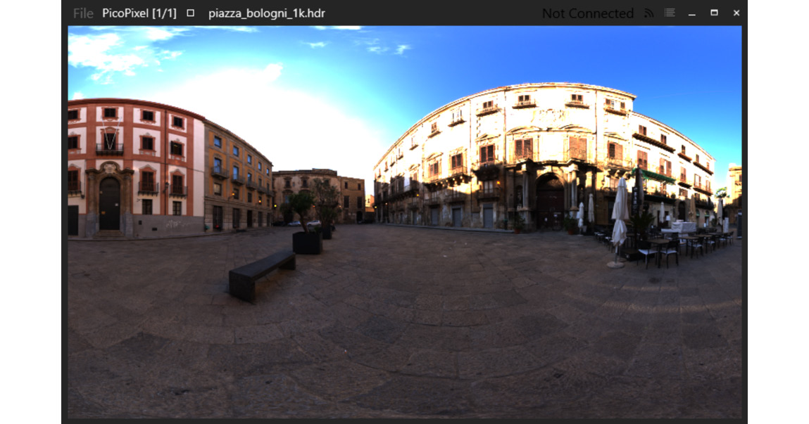
Figure 3.2 – Equirectangular projection
Let's convert this project into a vertical cross. In vertical cross format, each cube map's face is represented as a rectangle inside the entire image, as follows:
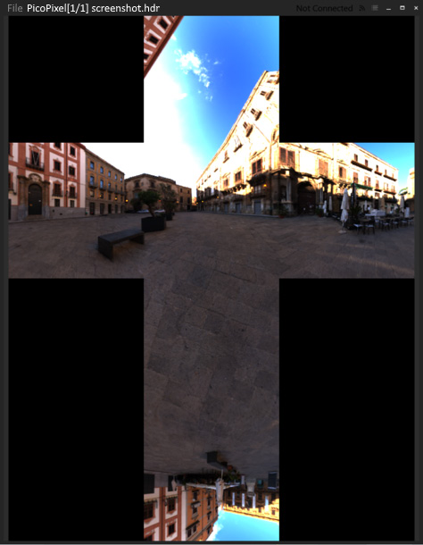
Figure 3.3 – Vertical cross
If we naively convert the equirectangular projection into cube map faces by iterating over its pixels, calculating the Cartesian coordinates for each pixel, and saving the pixel into a cube map face using these Cartesian coordinates, we will end up with a texture that's been heavily damaged by a Moiré pattern. Here, it's best to do things the other way around; that is, iterate over each pixel of the resulting cube map faces, calculate the source floating-point equirectangular coordinates corresponding to each pixel, and sample the equirectangular texture using bilinear interpolation. This way, the final cube map will be free of artifacts. Let's take a look at this:
- The first step is to introduce a helper function that maps integer coordinates inside a specified cube map face as floating-point normalized coordinates. This helper is handy because all the faces of the vertical cross cube map have different vertical orientations:
vec3 faceCoordsToXYZ( int i, int j, int faceID, int faceSize) {
const float A = 2.0f * float(i) / faceSize;
const float B = 2.0f * float(j) / faceSize;
if (faceID == 0) return vec3(-1.0f, A - 1.0f, B – 1.0f);
if (faceID == 1) return vec3(A - 1.0f, -1.0f, 1.0f - B);
if (faceID == 2) return vec3(1.0f, A - 1.0f, 1.0f - B);
if (faceID == 3) return vec3(1.0f - A, 1.0f, 1.0f - B);
if (faceID == 4) return vec3(B - 1.0f, A - 1.0f, 1.0f);
if (faceID == 5) return vec3(1.0f - B, A - 1.0f, -1.0f);
return vec3();
}
- The conversion function starts as follows and calculates the required faceSize, width, and height of the resulting bitmap:
Bitmap convertEquirectangularMapToVerticalCross( const Bitmap& b) {
if (b.type_ != eBitmapType_2D) return Bitmap();
const int faceSize = b.w_ / 4;
const int w = faceSize * 3;
const int h = faceSize * 4;
Bitmap result(w, h, 3);
- The following points define the locations of individual faces inside the cross:
const ivec2 kFaceOffsets[] = { ivec2(faceSize, faceSize * 3), ivec2(0, faceSize), ivec2(faceSize, faceSize), ivec2(faceSize * 2, faceSize), ivec2(faceSize, 0), ivec2(faceSize, faceSize * 2) };
- Two constants will be necessary to clamp the texture lookup:
const int clampW = b.w_ - 1;
const int clampH = b.h_ - 1;
- Now, we can start iterating over the six cube map faces and each pixel inside each face:
for (int face = 0; face != 6; face++) {
for (int i = 0; i != faceSize; i++) {
for (int j = 0; j != faceSize; j++) {
- Use trigonometry functions to calculate the latitude and longitude coordinates of the Cartesian cube map coordinates:
const vec3 P = faceCoordsToXYZ( i, j, face, faceSize);
const float R = hypot(P.x, P.y);
const float theta = atan2(P.y, P.x);
const float phi = atan2(P.z, R);
- Now, we can map the latitude and longitude of the floating-point coordinates inside the equirectangular image:
const float Uf = float(2.0f * faceSize * (theta + M_PI) / M_PI);
const float Vf = float(2.0f * faceSize * (M_PI / 2.0f – phi) / M_PI);
- Based on these floating-point coordinates, we will get two pairs of integer UV coordinates. We will use these to sample four texels for bilinear interpolation:
const int U1 = clamp(int(floor(Uf)), 0, clampW);
const int V1 = clamp(int(floor(Vf)), 0, clampH);
const int U2 = clamp(U1 + 1, 0, clampW);
const int V2 = clamp(V1 + 1, 0, clampH);
- Get the fractional part for bilinear interpolation:
const float s = Uf - U1;
const float t = Vf - V1;
- Fetch four samples from the equirectangular map:
const vec4 A = b.getPixel(U1, V1);
const vec4 B = b.getPixel(U2, V1);
const vec4 C = b.getPixel(U1, V2);
const vec4 D = b.getPixel(U2, V2);
- Perform bilinear interpolation and set the resulting pixel value in the vertical cross cube map:
const vec4 color = A * (1 - s) * (1 - t) + B * (s) * (1 - t) + C * (1 - s) * t + D * (s) * (t);
result.setPixel( i + kFaceOffsets[face].x, j + kFaceOffsets[face].y, color);
}
}
}
return result;
}
The Bitmap class takes care of the pixel format inside the image data.
Now, we can write some code to cut the vertical cross into tightly packed rectangular cube map faces. Here's how to do it:
- First, let's review the layout of the vertical cross image that corresponds to the OpenGL cube map faces layout:

Figure 3.4 – Layout of the vertical cross image
- The layout is 3x4 faces, which makes it possible to calculate the dimensions of the resulting cube map as follows:
Bitmap convertVerticalCrossToCubeMapFaces( const Bitmap& b) {
const int faceWidth = b.w_ / 3;
const int faceHeight = b.h_ / 4;
Bitmap cubemap( faceWidth, faceHeight, 6, b.comp_, b.fmt_);
- Let's set up some pointers to read and write the data. This function is pixel-format agnostic, so it needs to know the size of each pixel in bytes to be able to memcpy() pixels around:
const uint8_t* src = b.data_.data();
uint8_t* dst = cubemap.data_.data();
const int pixelSize = cubemap.comp_ * Bitmap::getBytesPerComponent(cubemap.fmt_);
- Iterate over the faces and over every pixel of each face. The order of the cube map faces here corresponds to the order of the OpenGL cube map faces, as defined by the GL_TEXTURE_CUBE_MAP_* constants:
for (int face = 0; face != 6; ++face) {
for (int j = 0; j != faceHeight; ++j) {
for (int i = 0; i != faceWidth; ++i) {
int x = 0;
int y = 0;
- Calculate the source pixel position in the vertical cross layout based on the destination cube map face index:
switch (face) {
// GL_TEXTURE_CUBE_MAP_POSITIVE_X case 0: x = i; y = faceHeight + j; break;
// GL_TEXTURE_CUBE_MAP_NEGATIVE_X case 1: x = 2 * faceWidth + i; y = 1 * faceHeight + j; break;
// GL_TEXTURE_CUBE_MAP_POSITIVE_Y case 2: x = 2 * faceWidth - (i + 1); y = 1 * faceHeight - (j + 1); break;
// GL_TEXTURE_CUBE_MAP_NEGATIVE_Y case 3: x = 2 * faceWidth - (i + 1); y = 3 * faceHeight - (j + 1); break;
// GL_TEXTURE_CUBE_MAP_POSITIVE_Z case 4: x = 2 * faceWidth - (i + 1); y = b.h_ - (j + 1); break;
// GL_TEXTURE_CUBE_MAP_NEGATIVE_Z case 5: x = faceWidth + i; y = faceHeight + j; break;
}
- Copy the pixel and advance to the next one:
memcpy(dst, src + (y * b.w_ + x) * pixelSize, pixelSize);
dst += pixelSize;
}
}
}
return cubemap;
}
The resulting cube map contains a stack of six images. Let's write some more C++ code to load and convert the actual texture data and upload it to OpenGL.
- Use the STB_image floating-point API to load a high dynamic range image from a .hdr file:
int w, h, comp;
const float* img = stbi_loadf( "data/piazza_bologni_1k.hdr", &w, &h, &comp, 3);
Bitmap in(w, h, comp, eBitmapFormat_Float, img);
stbi_image_free((void*)img);
- Convert an equirectangular map into a vertical cross and save the resulting image in a .hdr file for further inspection:
Bitmap out = convertEquirectangularMapToVerticalCross(in);
stbi_write_hdr("screenshot.hdr", out.w_, out.h_, out.comp_, reinterpret_cast<const float*>(out.data_.data()));
- Convert the vertical cross into the actual cube map faces:
Bitmap cm = convertVerticalCrossToCubeMapFaces(out);
- Now, uploading to OpenGL is straightforward. All we need to do is create a texture, set the texture parameters, allocate storage for an RGB floating-point texture, and upload the individual faces one by one. Note how the glTextureSubImage3D() function is used to upload individual cube map faces. The zoffset parameter of the function is used to specify the i index of the face:
glCreateTextures(GL_TEXTURE_CUBE_MAP, 1, &tex);
glTextureParameteri( tex, GL_TEXTURE_WRAP_S, GL_CLAMP_TO_BORDER);
glTextureParameteri( tex, GL_TEXTURE_WRAP_T, GL_CLAMP_TO_BORDER);
glTextureParameteri( tex, GL_TEXTURE_WRAP_R, GL_CLAMP_TO_BORDER);
glTextureParameteri( tex, GL_TEXTURE_MIN_FILTER, GL_LINEAR);
glTextureParameteri( tex, GL_TEXTURE_MAG_FILTER, GL_LINEAR);
glTextureStorage2D(tex, 1, GL_RGB32F, cm.w_, cm.h_);
const uint8_t* data = cm.data_.data();
for (unsigned i = 0; i != 6; ++i) {
glTextureSubImage3D(tex, 0, 0, 0, i, cm.w_, cm.h_, 1, GL_RGB, GL_FLOAT, data);
data += cm.w_ * cm.h_ * cm.comp_ * Bitmap::getBytesPerComponent(cm.fmt_);
}
Now, let's learn how to write the GLSL shaders for this example:
- Let's make the vertex shader take a separate model matrix and a world space camera position as its inputs:
layout(std140, binding = 0) uniform PerFrameData {
uniform mat4 model;
uniform mat4 MVP;
uniform vec4 cameraPos;
};
- The per-vertex output should be calculated as follows. Positions, normal vectors, and texture coordinates are read from the SSBO buffer using the PVP technique we discussed in the previous recipe. Normal vectors are transformed with a matrix calculated as the inverse transpose of the model matrix:
struct PerVertex {
vec2 uv;
vec3 normal;
vec3 worldPos;
};
layout (location=0) out PerVertex vtx;
void main() {
vec3 pos = getPosition(gl_VertexID);
gl_Position = MVP * vec4(pos, 1.0);
mat3 normalMatrix = mat3(transpose(inverse(model)));
vtx.uv = getTexCoord(gl_VertexID);
vtx.normal = getNormal(gl_VertexID) * normalMatrix;
vtx.worldPos = (model * vec4(pos, 1.0)).xyz;
}
- The fragment shader uses samplerCube to sample the cube map. Reflected and refracted direction vectors are calculated using GLSL's built-in reflect() and refract() functions, respectively:
layout (binding = 0) uniform sampler2D texture0;
layout (binding = 1) uniform samplerCube texture1;
void main() {
vec3 n = normalize(vtx.normal);
vec3 v = normalize(cameraPos.xyz - vtx.worldPos);
vec3 reflection = -normalize(reflect(v, n));
- To add some more complicated visual appearances, use the index of refraction of ice and calculate the specular reflection coefficient using Schlick's approximation (https://en.wikipedia.org/wiki/Schlick%27s_approximation):
float eta = 1.00 / 1.31;
vec3 refraction = -normalize(refract(v, n, eta));
const float R0 = ((1.0-eta) * (1.0-eta)) / ((1.0+eta) * (1.0+eta));
const float Rtheta = R0 + (1.0 – R0) * pow((1.0 – dot(-v, n)), 5.0);
vec4 color = texture(texture0, vtx.uv);
- Sample the cube map using the calculated direction vectors:
vec4 colorRefl = texture(texture1, reflection);
vec4 colorRefr = texture(texture1, refraction);
- The combined reflection and refraction color is modulated here with the diffuse texture to produce a clean looking image. It doesn't attempt to physically correct the process:
color = color * mix(colorRefl, colorRefr, Rtheta);
out_FragColor = color;
};
The resulting output from the application looks as follows. Note the blown out white areas of the sky due to how a high dynamic range image is being displayed directly on a low dynamic range framebuffer. We will come back to this issue in Chapter 8, Image-Based Techniques, and implement a simple tone mapping operator:

Figure 3.5 – Reflective rubber duck
There's more...
Modern rendering APIs can filter cube maps seamlessly across all faces. To enable this feature for all cube map textures in the current OpenGL context, use glEnable():
glEnable(GL_TEXTURE_CUBE_MAP_SEAMLESS);
Besides that, seamless cube map filtering can be enabled on a per-texture basis using the ARB_seamless_cubemap_per_texture extension, as follows:
glTextureParameteri(tex, GL_TEXTURE_CUBE_MAP_SEAMLESS,
GL_TRUE);
Make sure you use this OpenGL functionality since seamless cube map filtering is almost always what you want from a cube map.
In Vulkan, all cube map texture fetches are seamless (see Cube Map Edge Handling in the Vulkan specification), except the ones with VK_FILTER_NEAREST enabled on them, which are clamped to the face edge.
Compiling Vulkan shaders at runtime
In the previous recipes, we only covered OpenGL, while Vulkan was only mentioned a few times now and again. In the rest of this chapter, we will show you how to create a Vulkan rendering application with functionality similar to what we've done with OpenGL so far. The code from this and the subsequent recipes will be reused later to build more complex Vulkan demos.
Before we start using Vulkan, we must learn how to significantly speed up the iterative process of writing shaders. Vulkan consumes shaders in their final compiled binary form, called SPIR-V, and it uses a standalone shader compiler to precompile shaders offline. While being perfect for a released product, this approach slows down early stages of graphics application development and rapid prototyping, where shaders are changed a lot and should be recompiled on each application run. In this recipe, we will show you how to compile Vulkan shaders at runtime using Kronos' reference shader compiler, known as glslang.
Getting ready
Our application is statically linked to the glslang shader compiler. The compiler version we used in this recipe was downloaded using the following Bootstrap snippet:
{
"name": "glslang",
"source": {
"type": "git",
"url": "https://github.com/KhronosGroup/glslang.git",
"revision": "6fe560f74f472726027e4059692c6eb1e7d972dc"
}
}
The complete source code for this recipe can be found in this book's source code bundle, under the name Chapter3/VK01_GLSLang.
How to do it...
Let's learn how to compile a shader using glslang:
- First, we should declare storage for our compiled binary SPIR-V shaders:
struct ShaderModule {
std::vector<unsigned int> SPIRV;
VkShaderModule shaderModule;
};
- Use the following helper function to compile a shader from its source code for a specified Vulkan pipeline stage; then, save the binary SPIR-V result in the ShaderModule structure:
size_t compileShader(glslang_stage_t stage, const char* shaderSource, ShaderModule& shaderModule) {
- The compiler's input structure initialization is pretty verbose. We should specify the source shader language as GLSLANG_SOURCE_GLSL and use proper targets to generate SPIR-V 1.3 for Vulkan version 1.1. Using the new C++20 feature known as designated initializers for this task is a breeze. The same applies to low-level Vulkan development in general, since the most frequent thing a developer will do is fill in structure members with values:
const glslang_input_t input = { .language = GLSLANG_SOURCE_GLSL, .stage = stage, .client = GLSLANG_CLIENT_VULKAN, .client_version = GLSLANG_TARGET_VULKAN_1_1, .target_language = GLSLANG_TARGET_SPV, .target_language_version =GLSLANG_TARGET_SPV_1_3, .code = shaderSource, .default_version = 100, .default_profile = GLSLANG_NO_PROFILE, .force_default_version_and_profile = false, .forward_compatible = false, .messages = GLSLANG_MSG_DEFAULT_BIT, .resource = (const glslang_resource_t*) &glslang::DefaultTBuiltInResource,
};
- Let's create a shader using the constructed input:
glslang_shader_t* shd = glslang_shader_create(&input);
- First, the shader needs to be preprocessed by the compiler. This function returns true if all the extensions, pragmas, and version strings mentioned in the shader source code are valid:
if ( !glslang_shader_preprocess(shd, &input) ) {
fprintf(stderr, "GLSL preprocessing failed " );
fprintf(stderr, " %s", glslang_shader_get_info_log(shd));
fprintf(stderr, " %s", glslang_shader_get_info_debug_log(shd));
fprintf(stderr, "code: %s", input.code );
return 0;
}
- Then, the shader gets parsed in an internal parse tree representation inside the compiler:
if ( !glslang_shader_parse(shd, &input) ) {
fprintf(stderr, "GLSL parsing failed ");
fprintf(stderr, " %s", glslang_shader_get_info_log(shd) );
fprintf(stderr, " %s", glslang_shader_get_info_debug_log(shd));
fprintf(stderr, "%s", glslang_shader_get_preprocessed_code(shd));
return 0;
}
- If everything went well during the previous stages, we can link the shader to a program and proceed with the binary code generation stage:
glslang_program_t* prog = glslang_program_create();
glslang_program_add_shader(prog, shd);
int msgs = GLSLANG_MSG_SPV_RULES_BIT | GLSLANG_MSG_VULKAN_RULES_BIT;
if ( !glslang_program_link(prog, msgs) ) {
fprintf(stderr, "GLSL linking failed ");
fprintf(stderr, " %s", glslang_program_get_info_log(prog));
fprintf(stderr, " %s", glslang_program_get_info_debug_log(prog));
return 0;
}
- Generate some binary SPIR-V code and store it inside the shaderModule output variable:
glslang_program_SPIRV_generate(prog, stage);
shaderModule.SPIRV.resize( glslang_program_SPIRV_get_size(prog));
glslang_program_SPIRV_get( prog, shaderModule.SPIRV.data());
- Some messages may be produced by the code generator. Check and print them if there are any:
const char* spirv_messages = glslang_program_SPIRV_get_messages(prog);
if (spirv_messages)
fprintf(stderr, "%s", spirv_messages);
- Clean up and return the number of uint32_t values in the generated binary blob. This is how Vulkan requires the size to be specified:
glslang_program_delete(program);
glslang_shader_delete(shader);
return shaderModule.SPIRV.size();
}
How it works...
The demo application is straightforward: it loads the shader source code from a text file and uses the compileShader() function we just wrote to compile it into SPIR-V:
size_t compileShaderFile( const char* file, ShaderModule& shaderModule)
{
if (auto shaderSource = readShaderFile(file); !shaderSource.empty())
return compileShader( glslangShaderStageFromFileName(file), shaderSource.c_str(), shaderModule);
return 0;
}
Each generated SPIR-V binary blob is saved in a file for further inspection:
void testShaderCompilation( const char* sourceFilename, const char* destFilename)
{
ShaderModule;
if (compileShaderFile(sourceFilename, shaderModule) < 1) return;
saveSPIRVBinaryFile(destFilename, shaderModule.SPIRV.data(), shaderModule.SPIRV.size());
}
The main() function, which drives the demo application, initializes the glslang compiler and runs the necessary tests:
int main() {
glslang_initialize_process();
testShaderCompilation( "data/shaders/chapter03/VK01.vert", "VK01.vrt.bin");
testShaderCompilation( "data/shaders/chapter03/VK01.frag", "VK01.frg.bin");
glslang_finalize_process();
return 0;
}
The aforementioned program produces the same SPIR-V output as the following commands:
glslangValidator -V110 --target-env spirv1.3 VK01.vert -o VK01.vrt.bin
glslangValidator -V110 --target-env spirv1.3 VK01.frag -o VK01.frg.bin
There's more...
While being convenient during application development phases, shipping a big compiler alongside a release version of your application is a questionable practice. Unless compiling shaders at runtime is a feature of your application, you should prefer shipping precompiled SPIR-V shader binaries in the release version. One transparent way to do this is to implement a shader caching mechanism in your application. Once a shader is required, the application checks if a compiled shader is present. If there are none, it can load the glslang compiler from .dll or .so at runtime and compile the shader. This way, you can ensure that you always have compiled shaders for the release version of your app and that you do not need to ship shared libraries of the compiler.
If you want to learn how to load compiled shaders from .bin files produced by glslangValidator, take a look at this tutorial: https://vulkan-tutorial.com/Drawing_a_triangle/Graphics_pipeline_basics/Shader_modules.
Initializing Vulkan instances and graphical devices
The new Vulkan API is much more verbose, so we must split creating a graphical demo into separate, smaller recipes. In this recipe, we will learn how to create a Vulkan instance, enumerate all the physical devices in the system that are capable of 3D graphics rendering, and initialize one of these devices to create a window with an attached surface.
Getting ready
Teaching Vulkan from scratch is not the goal of this book, so we recommend starting with the book Vulkan Cookbook, published by Packt, and Vulkan Programming Guide: The Official Guide to Learning Vulkan, by Addison-Wesley Professional.
The hardest part of transitioning from OpenGL to Vulkan, or any other similar modern graphics API, is getting used to the amount of explicit code necessary to set up the rendering process, which, thankfully, only needs to be done once. It is also useful to get a grasp of Vulkan's object model. As a good starting point, we recommend reading https://gpuopen.com/understanding-vulkan-objects/ as a reference. For the remaining recipes in this chapter, we aim to start rendering 3D scenes with the bare minimum amount of setup.
All our Vulkan recipes use the Volk meta loader for the Vulkan API, which can be downloaded from https://github.com/zeux/volk using the following Bootstrap snippet. The meta loader allows you to dynamically load the entry points required to use Vulkan, without having to statically link any Vulkan loaders:
{
"name": "volk",
"source": {
"type": "git",
"url": "https://github.com/zeux/volk.git",
"revision": "1.2.170"
}
}
The complete Vulkan example for this recipe can be found in Chapter3/VK02_DemoApp.
How to do it...
Let's start with some error checking facilities:
- Any function call from a complex API may fail. To handle failure, or to at least let the developer know the exact location of the failure, we can wrap most of the Vulkan calls in the VK_CHECK() and VK_CHECK_RET() macros, which internally call the following VK_ASSERT() function:
static void VK_ASSERT(bool check) {
if (!check) exit(EXIT_FAILURE);
}
- The VK_CHECK() and VK_CHECK_RET() macros compare the result of a Vulkan call with the success value and return either a Boolean flag or a result value. If the comparison fails, the program should exit immediately:
#define VK_CHECK(value) if ( value != VK_SUCCESS ) { VK_ASSERT(false); return false; }
#define VK_CHECK_RET(value) if ( value != VK_SUCCESS ) { VK_ASSERT(false); return value; }
Now, we can start creating our first Vulkan object. The VkInstance object serves as an interface to the Vulkan API:
- The createInstance() routine is called at the beginning of the initialization process. Using the Vulkan instance, we can acquire a list of physical devices with the required properties:
void createInstance(VkInstance* instance) {
- First, we will declare a list of so-called layers, which will allow us to enable debugging output for every Vulkan call. The only layer we will be using is the debugging layer:
const std::vector<const char*> layers = {
"VK_LAYER_KHRONOS_validation"
};
- Next, we must declare the array with a list of extensions. The minimum number of extensions to allow rendering to take place is two. We need VK_KHR_surface and another platform-specific extension that takes an OS window handle and attaches a rendering surface to it. Amazingly, the following code is the only part of this example that explicitly requires us to use macros to detect the OS and assign the extension name:
const std::vector<const char*> exts = {
"VK_KHR_surface",
#if defined (WIN32)
"VK_KHR_win32_surface",
#endif
- macOS is supported via the MoltenVK implementation. However, most of the examples in this book are based on Vulkan 1.2, which is not supported by MoltenVK yet:
#if defined (__APPLE__)
"VK_MVK_macos_surface",
#endif
- On Linux, only libXCB-based window creation is supported. Similarly, the Wayland protocol is also supported, but that is outside the scope of this book:
#if defined (__linux__)
"VK_KHR_xcb_surface",
#endif
VK_EXT_DEBUG_UTILS_EXTENSION_NAME,
VK_EXT_DEBUG_REPORT_EXTENSION_NAME
};
- After constructing the list of surface-related extensions, we should fill in some mandatory information about our application:
const VkApplicationInfo appInfo = { .sType = VK_STRUCTURE_TYPE_APPLICATION_INFO, .pNext = nullptr, .pApplicationName = "Vulkan", .applicationVersion = VK_MAKE_VERSION(1, 0, 0), .pEngineName = "No Engine", .engineVersion = VK_MAKE_VERSION(1, 0, 0), .apiVersion = VK_API_VERSION_1_1 };
- To create a VkInstance object, we should fill in the VkInstanceCreateInfo structure. Use a pointer to the aforementioned appInfo constant and the list of extensions in the member fields of createInfo:
const VkInstanceCreateInfo createInfo = { .sType = VK_STRUCTURE_TYPE_INSTANCE_CREATE_INFO, .pNext = nullptr, .flags = 0, .pApplicationInfo = &appInfo, .enabledLayerCount = static_cast<uint32_t>(layers.size()), .ppEnabledLayerNames = layers.data(), .enabledExtensionCount = static_cast<uint32_t>(exts.size()), .ppEnabledExtensionNames = exts.data() };
VK_ASSERT(vkCreateInstance( &createInfo, nullptr, instance) == VK_SUCCESS);
- Finally, we must ask the Volk library to retrieve all the Vulkan API function pointers for all the extensions that are available for the created VkInstance:
volkLoadInstance(*instance);
}
Once we have a Vulkan instance ready and the graphics queue index set up with the selected physical device, we can create a logical representation of a GPU. Vulkan treats all devices as a collection of queues and memory heaps. To use a device for rendering, we need to specify a queue that can execute graphics-related commands, and a physical device that has such a queue. Let's get started:
- The createDevice() function accepts a list of required device features (for example, geometry shader support), a graphics queue index, a physical device, and an output handle for the logical device as input:
VkResult createDevice(
VkPhysicalDevice physicalDevice,
VkPhysicalDeviceFeatures deviceFeatures,
uint32_t graphicsFamily,
VkDevice* device)
{
- Let's declare a list of extensions that our logical device must support. For our early demos, we need the device to support the swap chain object, which allows us to present rendered frames on the screen. This list is going to be extended in subsequent chapters:
const std::vector<const char*> extensions = { VK_KHR_SWAPCHAIN_EXTENSION_NAME };
- We will only use a single graphics queue that has maximum priority:
const float queuePriority = 1.0f;
const VkDeviceQueueCreateInfo qci = { .sType =VK_STRUCTURE_TYPE_DEVICE_QUEUE_CREATE_INFO, .pNext = nullptr, .flags = 0, .queueFamilyIndex = graphicsFamily, .queueCount = 1, .pQueuePriorities = &queuePriority
};
- To create something in Vulkan, we should fill in a ...CreateInfo structure and pass all the required object properties to an appropriate vkCreate...() function. Here, we will define a VkDeviceCreateInfo constant with a reference to a single queue:
const VkDeviceCreateInfo ci = { .sType = VK_STRUCTURE_TYPE_DEVICE_CREATE_INFO, .pNext = nullptr, .flags = 0, .queueCreateInfoCount = 1, .pQueueCreateInfos = &qci, .enabledLayerCount = 0, .ppEnabledLayerNames = nullptr, .enabledExtensionCount = static_cast<uint32_t>(extensions.size()), .ppEnabledExtensionNames = extensions.data(), .pEnabledFeatures = &deviceFeatures
};
return vkCreateDevice( physicalDevice, &ci, nullptr, device );
}
- The createDevice() function expects a reference to a physical graphics-capable device. The following function finds such a device:
VkResult findSuitablePhysicalDevice(
VkInstance instance,
std::function<bool(VkPhysicalDevice)> selector,
VkPhysicalDevice* physicalDevice)
{
uint32_t deviceCount = 0;
VK_CHECK_RET(vkEnumeratePhysicalDevices(instance, &deviceCount, nullptr));
if (!deviceCount) return VK_ERROR_INITIALIZATION_FAILED;
std::vector<VkPhysicalDevice> devices(deviceCount);
VK_CHECK_RET(vkEnumeratePhysicalDevices( instance, &deviceCount, devices.data()));
for (const auto& device : devices)
if (selector(device)) {
*physicalDevice = device;
return VK_SUCCESS;
}
return VK_ERROR_INITIALIZATION_FAILED;
}
- Once we have a physical device reference, we will get a list of its queues. Here, we must check for the one with our desired capability flags:
uint32_t findQueueFamilies(
VkPhysicalDevice device, VkQueueFlags desiredFlags)
{
uint32_t familyCount;
vkGetPhysicalDeviceQueueFamilyProperties( device, &familyCount, nullptr);
std::vector<VkQueueFamilyProperties> families(familyCount);
vkGetPhysicalDeviceQueueFamilyProperties( device, &familyCount, families.data());
for (uint32_t i = 0; i != families.size(); i++)
if ( families[i].queueCount && (families[i].queueFlags & desiredFlags) )
return i;
return 0;
}
At this point, we have selected a suitable physical device, but we are far from finished with rendering the Vulkan pipeline. The next thing we will do is create a swap chain object. Let's move on to the next recipe to learn how to do this.
Initializing the Vulkan swap chain
Normally, each frame is rendered as an offscreen image. Once the rendering process is complete, the offscreen image should be made visible. An object that holds a collection of available offscreen images – or, more specifically, a queue of rendered images waiting to be presented to the screen – is called a swap chain. In OpenGL, presenting an offscreen buffer to the visible area of a window is performed using system-dependent functions, namely wglSwapBuffers() on Windows, eglSwapBuffers() on OpenGL ES embedded systems, glXSwapBuffers() on Linux, and automatically on macOS. Using Vulkan, we need to select a sequencing algorithm for the swap chain images. Also, the operation that presents an image to the display is no different from any other operation, such as rendering a collection of triangles. The Vulkan API object model treats each graphics device as a collection of command queues where rendering, computation, or transfer operations can be enqueued.
In this recipe, we will show you how to create a Vulkan swap chain object using the Vulkan instance and graphical device we initialized in the previous recipe.
Getting ready
Revisit the previous recipe, which discusses Vulkan instance creation and enabling the validation layer.
How to do it...
Before we can create a swap chain object, we need some helper functions:
- First, let's write a function that retrieves swap chain support details based on the specified physical device and the Vulkan surface. The result is returned inside the SwapchainSupportDetails structure:
struct SwapchainSupportDetails {
VkSurfaceCapabilitiesKHR capabilities = {};
std::vector<VkSurfaceFormatKHR> formats;
std::vector<VkPresentModeKHR> presentModes;
};
SwapchainSupportDetails querySwapchainSupport(
VkPhysicalDevice device, VkSurfaceKHR surface) {
- Query the basic capabilities of a surface:
SwapchainSupportDetails details;
vkGetPhysicalDeviceSurfaceCapabilitiesKHR( device, surface, &details.capabilities);
- Get the number of available surface formats. Allocate the storage to hold them:
uint32_t formatCount;
vkGetPhysicalDeviceSurfaceFormatsKHR( device, surface, &formatCount, nullptr);
if (formatCount) {
details.formats.resize(formatCount);
vkGetPhysicalDeviceSurfaceFormatsKHR( device, surface, &formatCount, details.formats.data());
}
- Retrieve the supported presentation modes in a similar way:
uint32_t presentModeCnt;
vkGetPhysicalDeviceSurfacePresentModesKHR( device, surface, &presentModeCnt, nullptr);
if (presentModeCnt) {
details.presentModes.resize(presentModeCnt);
vkGetPhysicalDeviceSurfacePresentModesKHR( device, surface, &presentModeCnt, details.presentModes.data());
}
return details;
}
- Let's write a helper function for choosing the required surface format. We will use a hardcoded value here for the RGBA 8-bit per channel format with the sRGB color space:
VkSurfaceFormatKHR chooseSwapSurfaceFormat( const std::vector<VkSurfaceFormatKHR>& availableFormats) {
return { VK_FORMAT_B8G8R8A8_UNORM,VK_COLOR_SPACE_SRGB_ NONLINEAR_KHR};
}
- Now, we should select presentation mode. The preferred presentation mode is VK_PRESENT_MODE_MAILBOX_KHR, which specifies that the Vulkan presentation system should wait for the next vertical blanking period to update the current image. Visual tearing will not be observed in this case. However, it's not guaranteed that this presentation mode will be supported. In this situation, we can always fall back to VK_PRESENT_MODE_FIFO_KHR. The differences between all possible presentation modes are described in the Vulkan specification at https://www.khronos.org/registry/vulkan/specs/1.1-extensions/man/html/VkPresentModeKHR.html:
VkPresentModeKHR chooseSwapPresentMode( const std::vector<VkPresentModeKHR>& availablePresentModes) {
for (const auto mode : availablePresentModes)
if (mode == VK_PRESENT_MODE_MAILBOX_KHR) return mode;
return VK_PRESENT_MODE_FIFO_KHR;
}
- The last helper function we need will choose the number of images in the swap chain object. It is based on the surface capabilities we retrieved earlier. Instead of using minImageCount directly, we will request one additional image to make sure we are not waiting on the GPU to complete any operations:
uint32_t chooseSwapImageCount( const VkSurfaceCapabilitiesKHR& caps)
{
const uint32_t imageCount = caps.minImageCount + 1;
const bool imageCountExceeded = caps.maxImageCount && imageCount > caps.maxImageCount;
return imageCountExceeded ? caps.maxImageCount : imageCount;
}
- Once we have all of our helper functions in place, the createSwapchain() wrapper function becomes rather short and mostly consists of filling in the VkSwapchainCreateInfoKHR structure:
VkResult createSwapchain( VkDevice device, VkPhysicalDevice physicalDevice, VkSurfaceKHR surface, uint32_t graphicsFamily, uint32_t width, uint32_t height, VkSwapchainKHR* swapchain)
{
auto swapchainSupport = querySwapchainSupport( physicalDevice, surface);
auto surfaceFormat = chooseSwapSurfaceFormat( swapchainSupport.formats);
auto presentMode = chooseSwapPresentMode( swapchainSupport.presentModes);
- Let's fill in the VkSwapchainCreateInfoKHR structure. Our initial example will not use a depth buffer, so only VK_IMAGE_USAGE_COLOR_ATTACHMENT_BIT will be used. The VK_IMAGE_USAGE_TRANSFER_DST_BIT flag specifies that the image can be used as the destination of a transfer command:
const VkSwapchainCreateInfoKHR ci = { .sType = VK_STRUCTURE_TYPE_SWAPCHAIN_CREATE_INFO_KHR, .flags = 0, .surface = surface, .minImageCount = chooseSwapImageCount( swapchainSupport.capabilities), .imageFormat = surfaceFormat.format, .imageColorSpace = surfaceFormat.colorSpace, .imageExtent = {.width = width, .height = height }, .imageArrayLayers = 1, .imageUsage = VK_IMAGE_USAGE_COLOR_ATTACHMENT_BIT | VK_IMAGE_USAGE_TRANSFER_DST_BIT, .imageSharingMode = VK_SHARING_MODE_EXCLUSIVE, .queueFamilyIndexCount = 1, .pQueueFamilyIndices = &graphicsFamily, .preTransform = swapchainSupport.capabilities.currentTransform, .compositeAlpha = VK_COMPOSITE_ALPHA_OPAQUE_BIT_KHR, .presentMode = presentMode, .clipped = VK_TRUE, .oldSwapchain = VK_NULL_HANDLE };
return vkCreateSwapchainKHR( device, &ci, nullptr, swapchain);
}
- Once the swapchain object has been created, we should retrieve the actual images from the swapchain. Use the following function to do so:
size_t createSwapchainImages( VkDevice device, VkSwapchainKHR swapchain, std::vector<VkImage>& swapchainImages, std::vector<VkImageView>& swapchainImageViews)
{
uint32_t imageCount = 0;
VK_ASSERT(vkGetSwapchainImagesKHR(device, swapchain, &imageCount, nullptr) == VK_SUCCESS);
swapchainImages.resize(imageCount);
swapchainImageViews.resize(imageCount);
VK_ASSERT(vkGetSwapchainImagesKHR(device, swapchain, &imageCount, swapchainImages.data()) == VK_SUCCESS);
for (unsigned i = 0; i < imageCount; i++)
if (!createImageView(device, swapchainImages[i], VK_FORMAT_B8G8R8A8_UNORM, VK_IMAGE_ASPECT_COLOR_BIT, &swapchainImageViews[i]))
exit(EXIT_FAILURE);
return imageCount;
}
- One last thing to mention is the helper function that creates an image view for us:
bool createImageView(VkDevice device, VkImage image, VkFormat format, VkImageAspectFlags aspectFlags, VkImageView* imageView)
{
const VkImageViewCreateInfo viewInfo = { .sType = VK_STRUCTURE_TYPE_IMAGE_VIEW_CREATE_INFO, .pNext = nullptr, .flags = 0, .image = image, .viewType = VK_IMAGE_VIEW_TYPE_2D, .format = format, .subresourceRange = { .aspectMask = aspectFlags, .baseMipLevel = 0, .levelCount = 1, .baseArrayLayer = 0, .layerCount = 1 }
};
VK_CHECK(vkCreateImageView(device, &viewInfo, nullptr, imageView));
return true;
}
Now, we can start the Vulkan initialization process. In the next recipe, we will show you how to catch errors that are encountered during the initialization phase.
Setting up Vulkan's debugging capabilities
Once we have created a Vulkan instance, we can start tracking all possible errors and warnings that may be produced by the validation layer. To do so, we should create a couple of callback functions and register them with the Vulkan instance. In this recipe, we will learn how to set up and use them.
How to do it...
There are two callback functions that catch the debug output from Vulkan: vulkanDebugCallback() and vulkanDebugReportCallback(). Let's get started:
- The first function, vulkanDebugCallback() prints all messages coming into the system console:
static VKAPI_ATTR VkBool32 VKAPI_CALL
vulkanDebugCallback( VkDebugUtilsMessageSeverityFlagBitsEXT Severity, VkDebugUtilsMessageTypeFlagsEXT Type, const VkDebugUtilsMessengerCallbackDataEXT* CallbackData, void* UserData)
{
printf("Validation layer: %s ", CallbackData->pMessage);
return VK_FALSE;
}
- vulkanDebugReportCallback() is more elaborate and provides information about an object that's causing an error or a warning. Some performance warnings are silenced to make the debug output more readable:
static VKAPI_ATTR VkBool32 VKAPI_CALL
vulkanDebugReportCallback( VkDebugReportFlagsEXT flags, VkDebugReportObjectTypeEXT objectType, uint64_t object, size_t location, int32_t messageCode, const char* pLayerPrefix, const char* pMessage, void* UserData)
{
if (flags & VK_DEBUG_REPORT_PERFORMANCE_WARNING_BIT_EXT)
return VK_FALSE;
printf("Debug callback (%s): %s ", pLayerPrefix, pMessage);
return VK_FALSE;
}
- To associate these callbacks with a Vulkan instance, we should create two more objects, messenger and reportCallback, in the following function. They will be destroyed at the end of the application:
bool setupDebugCallbacks( VkInstance instance, VkDebugUtilsMessengerEXT* messenger, VkDebugReportCallbackEXT* reportCallback)
{
const VkDebugUtilsMessengerCreateInfoEXT ci1 = { .sType = VK_STRUCTURE_TYPE_DEBUG_UTILS_MESSENGER _CREATE_INFO_EXT, .messageSeverity = VK_DEBUG_UTILS_MESSAGE_SEVERITY _WARNING_BIT_EXT | VK_DEBUG_UTILS_MESSAGE_SEVERITY_ERROR_BIT_EXT, .messageType = VK_DEBUG_UTILS_MESSAGE_TYPE_GENERAL_BIT_EXT| VK_DEBUG_UTILS_MESSAGE_TYPE_VALIDATION_BIT_EXT| VK_DEBUG_UTILS_MESSAGE_TYPE _PERFORMANCE_BIT_EXT, .pfnUserCallback = &VulkanDebugCallback, .pUserData = nullptr };
VK_CHECK(vkCreateDebugUtilsMessengerEXT( instance, &ci1, nullptr, messenger));
const VkDebugReportCallbackCreateInfoEXT ci2 = { .sType = VK_STRUCTURE_TYPE_DEBUG_REPORT _CALLBACK_CREATE_INFO_EXT, .pNext = nullptr, .flags = VK_DEBUG_REPORT_WARNING_BIT_EXT | VK_DEBUG_REPORT_PERFORMANCE_WARNING_BIT_EXT | VK_DEBUG_REPORT_ERROR_BIT_EXT | VK_DEBUG_REPORT_DEBUG_BIT_EXT, .pfnCallback = &VulkanDebugReportCallback, .pUserData = nullptr };
VK_CHECK(vkCreateDebugReportCallbackEXT(instance, &ci, nullptr,reportCallback));
return true;
}
This code is sufficient to get you started with reading the validation layer messages and debugging your Vulkan applications.
There's more…
To make our validation layers even more useful, we can add symbolic names to Vulkan objects. This is useful for debugging Vulkan applications in situations where the validation layer reports object handles. Use the following code snippet to do this:
bool setVkObjectName(VulkanRenderDevice& vkDev, void object, VkObjectType objType, const char name) {
VkDebugUtilsObjectNameInfoEXT nameInfo = { .sType = VK_STRUCTURE_TYPE_DEBUG_UTILS
_OBJECT_NAME_INFO_EXT, .pNext = nullptr, .objectType = objType, .objectHandle = (uint64_t)object, .pObjectName = name };
return (vkSetDebugUtilsObjectNameEXT(vkDev.device, &nameInfo) == VK_SUCCESS);
}
Also, please note that you should destroy the validation layer callbacks right before the Vulkan instance is destroyed. Check the full source code for details.
Tracking and cleaning up Vulkan objects
To keep things under control, we must carefully collect and recycle all our previously allocated Vulkan objects. In this recipe, we will learn how to keep track of allocated Vulkan objects and deallocate them properly at the end of our application.
Getting ready
Since Vulkan is an asynchronous interface, there must be a way to synchronize operations and ensure they complete. One of these synchronization objects is a semaphore. Here, we are declaring a helper function to create a semaphore:
VkResult createSemaphore( VkDevice device, VkSemaphore* outSemaphore) {
const VkSemaphoreCreateInfo ci = { .sType = VK_STRUCTURE_TYPE_SEMAPHORE_CREATE_INFO };
return vkCreateSemaphore( device, &ci, nullptr, outSemaphore);
}
Now, we can go ahead and use this function in this recipe.
How to do it...
Let's make the ad hoc approach to Vulkan initialization we used in the previous recipes more organized:
- First, we should combine all our related VkInstance objects into the following structure:
struct VulkanInstance {
VkInstance instance;
VkSurfaceKHR surface;
VkDebugUtilsMessengerEXT messenger;
VkDebugReportCallbackEXT reportCallback;
};
- In a similar way, all our related VkDevice objects should be combined into the VulkanRenderDevice structure. The new VkCommandPool and VkCommandBuffers objects will be discussed later. We will extend this structure with the Vulkan functionality in Chapter 6, Physically Based Rendering Using the glTF2 Shading Model:
struct VulkanRenderDevice {
VkDevice device;
VkQueue graphicsQueue;
VkPhysicalDevice physicalDevice;
uint32_t graphicsFamily;
VkSemaphore semaphore;
VkSemaphore renderSemaphore;
VkSwapchainKHR swapchain;
std::vector<VkImage> swapchainImages;
std::vector<VkImageView> swapchainImageViews;
VkCommandPool commandPool;
std::vector<VkCommandBuffer> commandBuffers;
};
- Now, we can proceed with the complete initialization routine of the Vulkan render device:
bool initVulkanRenderDevice( VulkanInstance& vk, VulkanRenderDevice& vkDev, uint32_t width, uint32_t height, std::function<bool(VkPhysicalDevice)> selector, VkPhysicalDeviceFeatures deviceFeatures)
{
VK_CHECK(findSuitablePhysicalDevice( vk.instance, selector, &vkDev.physicalDevice));
vkDev.graphicsFamily = findQueueFamilies(vkDev.physicalDevice, VK_QUEUE_GRAPHICS_BIT);
VK_CHECK(createDevice(vkDev.physicalDevice, deviceFeatures, vkDev.graphicsFamily, &vkDev.device));
vkGetDeviceQueue( vkDev.device, vkDev.graphicsFamily, 0, &vkDev.graphicsQueue);
if (vkDev.graphicsQueue == nullptr) exit(EXIT_FAILURE);
VkBool32 presentSupported = 0;
vkGetPhysicalDeviceSurfaceSupportKHR( vkDev.physicalDevice, vkDev.graphicsFamily, vk.surface, &presentSupported);
if (!presentSupported) exit(EXIT_FAILURE);
VK_CHECK(createSwapchain(vkDev.device, vkDev.physicalDevice, vk.surface, vkDev.graphicsFamily, width, height, &vkDev.swapchain));
const size_t imageCount = createSwapchainImages( vkDev.device, vkDev.swapchain, vkDev.swapchainImages, vkDev.swapchainImageViews);
vkDev.commandBuffers.resize(imageCount);
- There are two semaphores that are necessary for rendering. We will use the first one, called vkDev.semaphore, to ensure that the rendering process waits for the swap chain image to become available; the second one, called vkDev.renderSemaphore, will ensure that the presentation process waits for rendering to have completed:
VK_CHECK(createSemaphore(vkDev.device, &vkDev.semaphore));
VK_CHECK(createSemaphore(vkDev.device, &vkDev.renderSemaphore));
- A command pool is necessary to allocate command buffers:
const VkCommandPoolCreateInfo cpi = { .sType = VK_STRUCTURE_TYPE_COMMAND_POOL_CREATE_INFO, .flags = 0, .queueFamilyIndex = vkDev.graphicsFamily };
VK_CHECK(vkCreateCommandPool(vkDev.device, &cpi, nullptr, &vkDev.commandPool));
- Allocate one command buffer per swap chain image:
const VkCommandBufferAllocateInfo ai = { .sType = VK_STRUCTURE_TYPE_COMMAND_BUFFER_ALLOCATE_INFO, .pNext = nullptr, .commandPool = vkDev.commandPool, .level = VK_COMMAND_BUFFER_LEVEL_PRIMARY, .commandBufferCount = (uint32_t)(vkDev.swapchainImages.size())
};
VK_CHECK(vkAllocateCommandBuffers( vkDev.device, &ai, &vkDev.commandBuffers[0]));
return true;
}
- Deinitialization is straightforward. First, we should destroy everything stored inside the VulkanRenderDevice structure:
void destroyVulkanRenderDevice( VulkanRenderDevice& vkDev)
{
for (size_t i = 0; i < vkDev.swapchainImages.size();
i++)
vkDestroyImageView(vkDev.device, vkDev.swapchainImageViews[i], nullptr);
vkDestroySwapchainKHR( vkDev.device, vkDev.swapchain, nullptr);
vkDestroyCommandPool(vkDev.device, vkDev.commandPool, nullptr);
vkDestroySemaphore(vkDev.device, vkDev.semaphore, nullptr);
vkDestroySemaphore(vkDev.device,
vkDev.renderSemaphore, nullptr);
vkDestroyDevice(vkDev.device, nullptr);
}
- Now, the swap chain and Vulkan instance can be destroyed:
void destroyVulkanInstance(VulkanInstance& vk)
{
vkDestroySurfaceKHR( vk.instance, vk.surface, nullptr);
vkDestroyDebugReportCallbackEXT(vk.instance, vk.reportCallback, nullptr);
vkDestroyDebugUtilsMessengerEXT(vk.instance, vk.messenger, nullptr);
vkDestroyInstance(vk.instance, nullptr);
}
At this point, we have well-structured Vulkan initialization and deinitialization code, and we've also created the command pool and command buffers. In the next recipe, we will fill our first command buffers with drawing commands.
Using Vulkan command buffers
In the previous recipes, we learned how to create a Vulkan instance, a device for rendering, and a swap chain object with images and image views. In this recipe, we will learn how to fill command buffers and submit them using queues, which will bring us a bit closer to rendering our first image with Vulkan.
How to do it...
Let's prepare a command buffer that will begin a new render pass, clear the color and depth attachments, bind pipelines and descriptor sets, and render a mesh:
- First, we need to fill in a structure describing a command buffer:
bool fillCommandBuffers(size_t i) {
const VkCommandBufferBeginInfo bi = { .sType = VK_STRUCTURE_TYPE_COMMAND_BUFFER_BEGIN_INFO, .pNext = nullptr, .flags = VK_COMMAND_BUFFER_USAGE_SIMULTANEOUS_USE_BIT, .pInheritanceInfo = nullptr
};
- Now, we need an array of values to clear the framebuffer and VkRect2D to hold its dimensions:
const std::array<VkClearValue, 2> clearValues = { VkClearValue { .color = clearValueColor }, VkClearValue { .depthStencil = { 1.0f, 0 } } };
const VkRect2D screenRect = { .offset = { 0, 0 }, .extent = { .width = kScreenWidth, .height = kScreenHeight }
};
- Each command buffer corresponds to a separate image in the swap chain. Let's fill in the current one:
VK_CHECK(vkBeginCommandBuffer( vkDev.commandBuffers[i], &bi));
const VkRenderPassBeginInfo renderPassInfo = { .sType = VK_STRUCTURE_TYPE_RENDER_PASS_BEGIN_INFO, .pNext = nullptr, .renderPass = vkState.renderPass, .framebuffer = vkState.swapchainFramebuffers[i], .renderArea = screenRect, .clearValueCount = static_cast<uint32_t>(clearValues.size()), .pClearValues = clearValues.data() };
vkCmdBeginRenderPass(vkDev.commandBuffers[i], &renderPassInfo, VK_SUBPASS_CONTENTS_INLINE);
- Bind the pipeline and descriptor sets. In the subsequent recipes, we will show you how to set up pipelines, buffers, and descriptor sets to render a mesh:
vkCmdBindPipeline(vkDev.commandBuffers[i], VK_PIPELINE_BIND_POINT_GRAPHICS, vkState.graphicsPipeline);
vkCmdBindDescriptorSets(vkDev.commandBuffers[i], VK_PIPELINE_BIND_POINT_GRAPHICS, vkState.pipelineLayout, 0, 1, &vkState.descriptorSets[i], 0, nullptr);
vkCmdDraw( vkDev.commandBuffers[i], static_cast<uint32_t>(indexBufferSize / sizeof(uint32_t)), 1, 0, 0 );
vkCmdEndRenderPass(vkDev.commandBuffers[i]);
VK_CHECK(vkEndCommandBuffer( vkDev.commandBuffers[i]));
return true;
}
Now, we have a bunch of command buffers filled with commands that are ready to be submitted into a rendering queue. In the next recipe, we will learn how to use command buffers to transfer data.
See also
We recommend referring to Vulkan Cookbook, by Packt, for in-depth coverage of swap chain creation and command queue management.
Dealing with buffers in Vulkan
Buffers in Vulkan are regions of memory that store data that can be rendered on the GPU. To render a 3D scene using the Vulkan API, we must transform the scene data into a format that's suitable for the GPU. In this recipe, we will describe how to create a GPU buffer and upload vertex data into it.
Getting ready
Uploading data into GPU buffers is an operation that is executed, just like any other Vulkan operation, using command buffers. This means we need to have a command queue that's capable of performing transfer operations. We learned how to create and use command buffers earlier in this chapter, in the Using Vulkan command buffers recipe.
How to do it...
Let's create some helper functions for dealing with different buffers:
- First, we need the findMemoryType() function, which selects an appropriate heap type on the GPU, based on the required properties and a filter:
uint32_t findMemoryType( VkPhysicalDevice device, uint32_t typeFilter, VkMemoryPropertyFlags properties)
{
VkPhysicalDeviceMemoryProperties memProperties;
vkGetPhysicalDeviceMemoryProperties( device, &memProperties );
for (uint32_t i = 0; i < memProperties.memoryTypeCount; i++) {
if ((typeFilter & (1 << i)) && memProperties.memoryTypes[i].propertyFlags & properties) == properties)
return i;
}
return 0xFFFFFFFF;
}
- Now, we can write a function that will create a buffer object and an associated device memory region. We will use this function to create uniform, shader storage, and other types of buffers. The exact buffer usage is specified by the usage parameter. The access permissions for the memory block are specified by properties flags:
bool createBuffer( VkDevice device, VkPhysicalDevice physicalDevice, VkDeviceSize size, VkBufferUsageFlags usage, VkMemoryPropertyFlags properties, VkBuffer& buffer, VkDeviceMemory& bufferMemory)
{
const VkBufferCreateInfo bufferInfo = { .sType = VK_STRUCTURE_TYPE_BUFFER_CREATE_INFO, .pNext = nullptr, .flags = 0, .size = size, .usage = usage, .sharingMode = VK_SHARING_MODE_EXCLUSIVE, .queueFamilyIndexCount = 0, .pQueueFamilyIndices = nullptr };
VK_CHECK(vkCreateBuffer( device, &bufferInfo, nullptr, &buffer));
VkMemoryRequirements memRequirements;
vkGetBufferMemoryRequirements(device, buffer, &memRequirements);
const VkMemoryAllocateInfo ai = { .sType = VK_STRUCTURE_TYPE_MEMORY_ALLOCATE_INFO, .pNext = nullptr, .allocationSize = memRequirements.size, .memoryTypeIndex = findMemoryType(physicalDevice, memRequirements.memoryTypeBits, properties) };
VK_CHECK(vkAllocateMemory( device, &ai, nullptr, &bufferMemory));
vkBindBufferMemory(device, buffer, bufferMemory, 0);
return true;
}
- Once the buffer has been created, we can upload some data into a GPU buffer using the following routine:
void copyBuffer( VkDevice device, VkCommandPool commandPool, VkQueue graphicsQueue, VkBuffer srcBuffer, VkBuffer dstBuffer, VkDeviceSize size)
{
VkCommandBuffer commandBuffer = beginSingleTimeCommands(device, commandPool, graphicsQueue);
const VkBufferCopy copyParam = { .srcOffset = 0, .dstOffset = 0, .size = size };
vkCmdCopyBuffer(commandBuffer, srcBuffer, dstBuffer, 1,©Param);
endSingleTimeCommands(device, commandPool, graphicsQueue, commandBuffer);
}
- The copyBuffer() routine needs two helper functions to work. The first one is called beginSingleTimeCommands() and creates a temporary command buffer that contains transfer commands:
VkCommandBuffer beginSingleTimeCommands( VulkanRenderDevice& vkDev)
{
VkCommandBuffer commandBuffer;
const VkCommandBufferAllocateInfo allocInfo = { .sType = VK_STRUCTURE_TYPE_COMMAND_BUFFER_ALLOCATE_INFO, .pNext = nullptr, .commandPool = vkDev.commandPool, .level = VK_COMMAND_BUFFER_LEVEL_PRIMARY, .commandBufferCount = 1 };
vkAllocateCommandBuffers( vkDev.device, &allocInfo, &commandBuffer);
const VkCommandBufferBeginInfo beginInfo = { .sType = VK_STRUCTURE_TYPE_COMMAND_BUFFER_BEGIN_INFO, .pNext = nullptr, .flags = VK_COMMAND_BUFFER_USAGE_ONE_TIME_SUBMIT_BIT, .pInheritanceInfo = nullptr
};
vkBeginCommandBuffer(commandBuffer, &beginInfo);
return commandBuffer;
}
The second one is called endSingleTimeCommands() and submits the command buffer to the graphics queue and waits for the entire operation to complete:
void endSingleTimeCommands( VulkanRenderDevice& vkDev, VkCommandBuffer commandBuffer)
{
vkEndCommandBuffer(commandBuffer);
const VkSubmitInfo submitInfo = { .sType = VK_STRUCTURE_TYPE_SUBMIT_INFO, .pNext = nullptr, .waitSemaphoreCount = 0, .pWaitSemaphores = nullptr, .pWaitDstStageMask = nullptr, .commandBufferCount = 1, .pCommandBuffers = &commandBuffer, .signalSemaphoreCount = 0, .pSignalSemaphores = nullptr
};
vkQueueSubmit(vkDev.graphicsQueue, 1, &submitInfo, VK_NULL_HANDLE);
vkQueueWaitIdle(vkDev.graphicsQueue);
vkFreeCommandBuffers(vkDev.device, vkDev.commandPool, 1, &commandBuffer);
}
These functions will be used in the subsequent recipes to transfer geometry and image data to Vulkan buffers, as well as to convert data into different formats.
How it works...
Using this recipe, we can create a uniform buffer object for storing our combined model-view-projection matrix:
struct UniformBuffer {
mat4 mvp;
} ubo;
Let's look at the functions for creating a uniform buffer object and filling it with data. The first one creates a buffer that will store the UniformBuffer structure:
bool createUniformBuffers() {
VkDeviceSize bufferSize = sizeof(UniformBuffer);
vkState.uniformBuffers.resize( vkDev.swapchainImages.size());
vkState.uniformBuffersMemory.resize( vkDev.swapchainImages.size());
for (size_t i = 0; i<vkDev.swapchainImages.size(); i++) {
if (!createBuffer(vkDev.device, vkDev.physicalDevice, bufferSize, VK_BUFFER_USAGE_UNIFORM_BUFFER_BIT, VK_MEMORY_PROPERTY_HOST_VISIBLE_BIT | VK_MEMORY_PROPERTY_HOST_COHERENT_BIT, vkState.uniformBuffers[i], vkState.uniformBuffersMemory[i])) {
printf("Fail: buffers ");
return false;
}
}
return true;
}
The second one is called every frame to update our data in the buffer:
void updateUniformBuffer( uint32_t currentImage, const UniformBuffer& ubo)
{
void* data = nullptr;
vkMapMemory(vkDev.device, vkState.uniformBuffersMemory[currentImage], 0, sizeof(ubo), 0, &data);
memcpy(data, &ubo, sizeof(ubo));
vkUnmapMemory(vkDev.device, vkState.uniformBuffersMemory[currentImage]);
}
We will use these in the final recipe of this chapter; that is, Putting it all together into a Vulkan application.
Using texture data in Vulkan
Before we can write a meaningful 3D rendering application with Vulkan, we need to learn how to deal with textures. This recipe will show you how to implement several functions for creating, destroying, and modifying texture objects on the GPU using the Vulkan API.
Getting ready
Uploading texture data to a GPU requires a staging buffer. Read the previous recipe, Dealing with buffers in Vulkan, before you proceed further.
The complete source code for these functions can be found in the shared/UtilsVulkan.cpp source file.
How to do it...
The first thing we will do is create an image. A Vulkan image is another type of buffer that's designed to store a 1D, 2D, or 3D image, or even an array of these images. Those of you who are familiar with OpenGL are probably wondering about cube maps. Cube maps are special entities in Vulkan that are represented as an array of six 2D images, and they can be constructed by setting the VK_IMAGE_CREATE_CUBE_COMPATIBLE_BIT flag inside the VkImageCreateInfo structure. We will come back to this later. For now, let's investigate a basic use case with just a 2D image:
- The createImage() function is similar to createBuffer() from the Dealing with buffers in Vulkan recipe. The difference is that vkBindImageMemory() is used instead of vkBindBufferMemory():
bool createImage( VkDevice device, VkPhysicalDevice physicalDevice, uint32_t width, uint32_t height, VkFormat format, VkImageTiling tiling, VkImageUsageFlags usage, VkMemoryPropertyFlags properties, VkImage& image, VkDeviceMemory& imageMemory )
{
const VkImageCreateInfo imageInfo = { .sType = VK_STRUCTURE_TYPE_IMAGE_CREATE_INFO, .pNext = nullptr, .flags = 0, .imageType = VK_IMAGE_TYPE_2D, .format = format, .extent = VkExtent3D { .width = width, .height = height,.depth = 1}, .mipLevels = 1, .arrayLayers = 1, .samples = VK_SAMPLE_COUNT_1_BIT, .tiling = tiling, .usage = usage, .sharingMode = VK_SHARING_MODE_EXCLUSIVE, .queueFamilyIndexCount = 0, .pQueueFamilyIndices = nullptr, .initialLayout = VK_IMAGE_LAYOUT_UNDEFINED };
VK_CHECK(vkCreateImage( device, &imageInfo, nullptr, &image));
VkMemoryRequirements memRequirements;
vkGetImageMemoryRequirements( device, image, &memRequirements);
const VkMemoryAllocateInfo ai = { .sType = VK_STRUCTURE_TYPE_MEMORY_ALLOCATE_INFO, .pNext = nullptr, .allocationSize = memRequirements.size, .memoryTypeIndex = findMemoryType( physicalDevice, memRequirements.memoryTypeBits, properties) };
VK_CHECK(vkAllocateMemory( device, &ai, nullptr, &imageMemory));
vkBindImageMemory(device, image, imageMemory, 0);
return true;
}
- An image is just a region in memory. Its internal structure, such as the number of layers for a cube map or the number of mipmap levels is has, is specified in the VkImageView object. The createImageView() function, which was shown in the Initializing the Vulkan swapchain recipe, creates an image view that's suitable for 2D textures.
- Having the texture data in GPU memory is not enough. We must create a sampler that allows our fragment shaders to fetch texels from the image. This simple wrapper on top of the vkCreateSampler() function is all we need to access 2D textures for now:
bool createTextureSampler( VkDevice device, VkSampler* sampler)
{
const VkSamplerCreateInfo samplerInfo = { .sType = VK_STRUCTURE_TYPE_SAMPLER_CREATE_INFO, .pNext = nullptr, .flags = 0, .magFilter = VK_FILTER_LINEAR, .minFilter = VK_FILTER_LINEAR, .mipmapMode = VK_SAMPLER_MIPMAP_MODE_LINEAR, .addressModeU = VK_SAMPLER_ADDRESS_MODE_REPEAT, .addressModeV = VK_SAMPLER_ADDRESS_MODE_REPEAT, .addressModeW = VK_SAMPLER_ADDRESS_MODE_REPEAT, .mipLodBias = 0.0f, .anisotropyEnable = VK_FALSE, .maxAnisotropy = 1, .compareEnable = VK_FALSE, .compareOp = VK_COMPARE_OP_ALWAYS, .minLod = 0.0f, .maxLod = 0.0f, .borderColor = VK_BORDER_COLOR_INT_OPAQUE_BLACK, .unnormalizedCoordinates = VK_FALSE
};
VK_CHECK(vkCreateSampler( device, &samplerInfo, nullptr, sampler));
return true;
}
- Finally, to upload the data to an image, we should implement a function similar to copyBuffer() from the previous recipe. The copyBufferToImage() function uses …SingleTimeCommands() helpers to copy the data:
void copyBufferToImage(VulkanRenderDevice& vkDev, VkBuffer buffer, VkImage image, uint32_t width, uint32_t height)
{
VkCommandBuffer commandBuffer = beginSingleTimeCommands(vkDev);
const VkBufferImageCopy region = { .bufferOffset = 0, .bufferRowLength = 0, .bufferImageHeight = 0, .imageSubresource = VkImageSubresourceLayers { .aspectMask = VK_IMAGE_ASPECT_COLOR_BIT, .mipLevel = 0, .baseArrayLayer = 0, .layerCount = 1 }, .imageOffset = VkOffset3D{ .x = 0,.y = 0,.z = 0 }, .imageExtent = VkExtent3D{ .width=width, .height=height, .depth=1 }
};
vkCmdCopyBufferToImage(commandBuffer, buffer, image, VK_IMAGE_LAYOUT_TRANSFER_DST_OPTIMAL, 1, ®ion);
endSingleTimeCommands(vkDev, commandBuffer);
}
- Since we're using an image, an image view, and an associated device memory block, we should declare a structure that will hold all three objects:
struct VulkanTexture {
VkImage image;
VkDeviceMemory imageMemory;
VkImageView imageView;
};
- The texture destruction process is straightforward and simply calls the appropriate vkDestroy...() functions:
void destroyVulkanTexture(VkDevice device, VulkanTexture& texture) {
vkDestroyImageView( device, texture.imageView, nullptr);
vkDestroyImage(device, texture.image, nullptr);
vkFreeMemory(device, texture.imageMemory, nullptr);
}
- The GPU may need to reorganize texture data internally for faster access. This reorganization happens when we insert a pipeline barrier operation into the graphics command queue. The following lengthy function handles the necessary format transitions for 2D textures and depth buffers. This function is necessary if you want to resolve all the validation layer warnings for swap chain images. We will quote the entire function here because it is not readily available in any online tutorials. This will also serve as a good starting point for cleaning up validation layer warnings:
void transitionImageLayout( VulkanRenderDevice& vkDev, VkImage image, VkFormat format, VkImageLayout oldLayout, VkImageLayout newLayout, uint32_t layerCount, uint32_t mipLevels)
{
VkCommandBuffer commandBuffer = beginSingleTimeCommands(vkDev);
transitionImageLayoutCmd(commandBuffer, image, format,oldLayout, newLayout, layerCount, mipLevels);
endSingleTimeCommands(vkDev, commandBuffer);
}
- The bulk of the transitionImageLayout() method consists of filling out the VkImageMemoryBarrier structure. Here, we are presenting all the use cases for the image transitions that are necessary for this chapter. Later, in Chapter 8, Image-Based Techniques, for image-based effects, we will add plenty of additional image and depth buffer transitions to this function:
void transitionImageLayoutCmd( VkCommandBuffer commandBuffer, VkImage image, VkFormat format, VkImageLayout oldLayout, VkImageLayout newLayout, uint32_t layerCount, uint32_t mipLevels)
{
VkImageMemoryBarrier barrier = { .sType = VK_STRUCTURE_TYPE_IMAGE_MEMORY_BARRIER, .pNext = nullptr, .srcAccessMask = 0, .dstAccessMask = 0, .oldLayout = oldLayout, .newLayout = newLayout, .srcQueueFamilyIndex = VK_QUEUE_FAMILY_IGNORED, .dstQueueFamilyIndex = VK_QUEUE_FAMILY_IGNORED, .image = image, .subresourceRange = VkImageSubresourceRange { .aspectMask = VK_IMAGE_ASPECT_COLOR_BIT, .baseMipLevel = 0, .levelCount = 1, .baseArrayLayer = 0, .layerCount = 1 }
};
VkPipelineStageFlags sourceStage, destinationStage;
if (newLayout == VK_IMAGE_LAYOUT_DEPTH_STENCIL_ATTACHMENT_OPTIMAL) {
barrier.subresourceRange.aspectMask = VK_IMAGE_ASPECT_DEPTH_BIT;
if (hasStencilComponent(format))
barrier.subresourceRange.aspectMask |= VK_IMAGE_ASPECT_STENCIL_BIT;
}
else {
barrier.subresourceRange.aspectMask = VK_IMAGE_ASPECT_COLOR_BIT;
}
if (oldLayout == VK_IMAGE_LAYOUT_UNDEFINED && newLayout == VK_IMAGE_LAYOUT_TRANSFER_DST_OPTIMAL) {
barrier.srcAccessMask = 0;
barrier.dstAccessMask = VK_ACCESS_TRANSFER_WRITE_BIT;
sourceStage = VK_PIPELINE_STAGE_TOP_OF_PIPE_BIT;
destinationStage = VK_PIPELINE_STAGE_TRANSFER_BIT;
}
else if (oldLayout == VK_IMAGE_LAYOUT_TRANSFER_DST_OPTIMAL && newLayout == VK_IMAGE_LAYOUT_SHADER_READ_ONLY_OPTIMAL)
{
barrier.srcAccessMask = VK_ACCESS_TRANSFER_WRITE_BIT;
barrier.dstAccessMask = VK_ACCESS_SHADER_READ_BIT;
sourceStage = VK_PIPELINE_STAGE_TRANSFER_BIT;
destinationStage = VK_PIPELINE_STAGE_FRAGMENT_SHADER_BIT;
}
else if (oldLayout == VK_IMAGE_LAYOUT_UNDEFINED && newLayout == VK_IMAGE_LAYOUT_DEPTH_STENCIL_ATTACHMENT_OPTIMAL)
{
barrier.srcAccessMask = 0;
barrier.dstAccessMask = VK_ACCESS_DEPTH_STENCIL_ATTACHMENT_READ_BIT | VK_ACCESS_DEPTH_STENCIL_ATTACHMENT_WRITE_BIT;
sourceStage = VK_PIPELINE_STAGE_TOP_OF_PIPE_BIT;
destinationStage = VK_PIPELINE_STAGE_EARLY_FRAGMENT_TESTS_BIT;
}
vkCmdPipelineBarrier( commandBuffer, sourceStage, destinationStage, 0, 0, nullptr, 0, nullptr, 1, &barrier );
}
- To support depth buffering in the subsequent examples in this book, we will implement a function that will create a depth buffer image object. However, before we can do that, we need three helper functions to find the appropriate image formats. The first function accepts the required format features and tiling options and returns the first suitable format that satisfies these requirements:
VkFormat findSupportedFormat(VkPhysicalDevice device, const std::vector<VkFormat>& candidates, VkImageTiling tiling, VkFormatFeatureFlags features)
{
const bool isLin = tiling == VK_IMAGE_TILING_LINEAR;
const bool isOpt = tiling == VK_IMAGE_TILING_OPTIMAL;
for (VkFormat format : candidates) {
VkFormatProperties props;
vkGetPhysicalDeviceFormatProperties( device, format, &props);
if (isLin && (props.linearTilingFeatures & features) == features)
return format;
else
if (isOpt && (props.optimalTilingFeatures & features) == features)
return format;
}
printf("Failed to find supported format! ");
exit(0);
}
- The other two functions find the requested depth format and check if it has a suitable stencil component:
VkFormat findDepthFormat(VkPhysicalDevice device) {
return findSupportedFormat(device, { VK_FORMAT_D32_SFLOAT, VK_FORMAT_D32_SFLOAT_S8_UINT, VK_FORMAT_D24_UNORM_S8_UINT }, VK_IMAGE_TILING_OPTIMAL, VK_FORMAT_FEATURE_DEPTH_STENCIL_ATTACHMENT_BIT);
}
bool hasStencilComponent(VkFormat format) {
return format == VK_FORMAT_D32_SFLOAT_S8_UINT || format == VK_FORMAT_D24_UNORM_S8_UINT;
}
- Now, we can create a depth image:
void createDepthResources(VulkanRenderDevice& vkDev, uint32_t width, uint32_t height, VulkanTexture& depth)
{
VkFormat depthFormat = findDepthFormat( vkDev.physicalDevice );
createImage(vkDev.device, vkDev.physicalDevice, width, height, depthFormat, VK_IMAGE_TILING_OPTIMAL, VK_IMAGE_USAGE_DEPTH_STENCIL_ATTACHMENT_BIT, VK_MEMORY_PROPERTY_DEVICE_LOCAL_BIT, depth.image, depth.imageMemory);
createImageView(vkDev.device, depth.image, depthFormat, VK_IMAGE_ASPECT_DEPTH_BIT, &depth.imageView);
transitionImageLayout(vkDev.device, vkDev.commandPool, vkDev.graphicsQueue, depth.image, depthFormat, VK_IMAGE_LAYOUT_UNDEFINED, VK_IMAGE_LAYOUT_DEPTH_STENCIL_ATTACHMENT_OPTIMAL);
}
- Finally, let's implement a simple function that will load a 2D texture from an image file to a Vulkan image. This function uses a staging buffer in a similar way to the vertex buffer creation function from the previous recipe:
bool createTextureImage(VulkanRenderDevice& vkDev, const char* filename, VkImage& textureImage, VkDeviceMemory& textureImageMemory)
{
int texWidth, texHeight, texChannels;
stbi_uc* pixels = stbi_load(filename, &texWidth, &texHeight, &texChannels, STBI_rgb_alpha);
VkDeviceSize imageSize = texWidth * texHeight * 4;
if (!pixels) {
printf("Failed to load [%s] texture ", filename);
return false;
}
- A staging buffer is necessary to upload texture data into the GPU via memory mapping. This buffer should be declared as VK_MEMORY_PROPERTY_HOST_VISIBLE_BIT:
VkBuffer stagingBuffer;
VkDeviceMemory stagingMemory;
createBuffer(vkDev.device, vkDev.physicalDevice, imageSize, VK_BUFFER_USAGE_TRANSFER_SRC_BIT, VK_MEMORY_PROPERTY_HOST_VISIBLE_BIT | VK_MEMORY_PROPERTY_HOST_COHERENT_BIT, stagingBuffer, stagingMemory);
void* data;
vkMapMemory(vkDev.device, stagingMemory, 0, imageSize, 0, &data);
memcpy( data, pixels, static_cast<size_t>(imageSize));
vkUnmapMemory(vkDev.device, stagingMemory);
- The actual image is located in the device memory and can't be accessed directly from the host:
createImage(vkDev.device, vkDev.physicalDevice, texWidth, texHeight, VK_FORMAT_R8G8B8A8_UNORM, VK_IMAGE_TILING_OPTIMAL, VK_IMAGE_USAGE_TRANSFER_DST_BIT | VK_IMAGE_USAGE_SAMPLED_BIT, VK_MEMORY_PROPERTY_DEVICE_LOCAL_BIT, textureImage, textureImageMemory);
transitionImageLayout(vkDev.device, vkDev.commandPool, vkDev.graphicsQueue, textureImage, VK_FORMAT_R8G8B8A8_UNORM, VK_IMAGE_LAYOUT_UNDEFINED, VK_IMAGE_LAYOUT_TRANSFER_DST_OPTIMAL);
copyBufferToImage(vkDev, stagingBuffer, textureImage, static_cast<uint32_t>(texWidth), static_cast<uint32_t>(texHeight));
transitionImageLayout(vkDev.device, vkDev.commandPool, vkDev.graphicsQueue, textureImage, VK_FORMAT_R8G8B8A8_UNORM, VK_IMAGE_LAYOUT_TRANSFER_DST_OPTIMAL, VK_IMAGE_LAYOUT_SHADER_READ_ONLY_OPTIMAL);
vkDestroyBuffer( vkDev.device, stagingBuffer, nullptr);
vkFreeMemory(vkDev.device, stagingMemory, nullptr);
stbi_image_free(pixels);
return true;
}
This code is sufficient for providing basic texturing capabilities for our first Vulkan demo. Now, let's learn how to deal with mesh geometry data.
Using mesh geometry data in Vulkan
No graphical application can survive without working with at least some geometry data. In this recipe, we will learn how to load meshes into Vulkan buffers using Assimp. We will use shader storage buffer objects (SSBOs) and implement the programmable vertex pulling (PVP) technique, similar to what we did in the Implementing programmable vertex pulling (PVP) in OpenGL recipe.
Getting ready
The implementation of programmable vertex pulling for Vulkan is quite similar to OpenGL's. Please revisit the Implementing programmable vertex pulling (PVP) in OpenGL recipe for more information. The complete source code for all the Vulkan recipes in this chapter can be found in Chapter3/VK02_DemoApp.
How to do it...
Let's load an indexed mesh with vertex and texture coordinates. The data format for the texture mesh is the same as it was in the OpenGL recipes:
- The following function loads a mesh via Assimp from a file into a Vulkan shader storage buffer. The loading part is identical to OpenGL:
bool createTexturedVertexBuffer( VulkanRenderDevice& vkDev, const char* filename, VkBuffer* storageBuffer, VkDeviceMemory* storageBufferMemory, size_t* vertexBufferSize, size_t* indexBufferSize)
{
const aiScene* scene = aiImportFile( filename, aiProcess_Triangulate);
if (!scene || !scene->HasMeshes()) {
printf("Unable to load %s ", filename);
exit( 255 );
}
const aiMesh* mesh = scene->mMeshes[0];
struct VertexData {
vec3 pos;
vec2 tc;
};
std::vector<VertexData> vertices;
for (unsigned i = 0; i != mesh->mNumVertices; i++) {
const aiVector3D v = mesh->mVertices[i];
const aiVector3D t = mesh->mTextureCoords[0][i];
vertices.push_back( { vec3(v.x, v.z, v.y), vec2(t.x, t.y) });
}
std::vector<unsigned int> indices;
for ( unsigned i = 0; i != mesh->mNumFaces; i++ )
for ( unsigned j = 0; j != 3; j++ )
indices.push_back( mesh->mFaces[i].mIndices[j]);
aiReleaseImport(scene);
- We need a staging buffer to upload the data into the GPU memory:
*vertexBufferSize = sizeof(VertexData) * vertices.size();
*indexBufferSize = sizeof(unsigned int) * indices.size();
VkDeviceSize bufferSize = *vertexBufferSize + *indexBufferSize;
VkBuffer stagingBuffer;
VkDeviceMemory stagingMemory;
createBuffer(vkDev.device, vkDev.physicalDevice, bufferSize, VK_BUFFER_USAGE_TRANSFER_SRC_BIT, VK_MEMORY_PROPERTY_HOST_VISIBLE_BIT | VK_MEMORY_PROPERTY_HOST_COHERENT_BIT, stagingBuffer, stagingMemory);
void* data;
vkMapMemory(vkDev.device, staginMemory, 0, bufferSize, 0, &data);
memcpy(data, vertices.data(), *vertexBufferSize);
memcpy((unsigned char *)data + *vertexBufferSize, indices.data(), *indexBufferSize);
vkUnmapMemory(vkDev.device, stagingMemory);
createBuffer(vkDev.device, vkDev.physicalDevice, bufferSize, VK_BUFFER_USAGE_TRANSFER_DST_BIT | VK_BUFFER_USAGE_STORAGE_BUFFER_BIT, VK_MEMORY_PROPERTY_DEVICE_LOCAL_BIT, *storageBuffer, *storageBufferMemory);
- The copyBuffer() function from the Dealing with buffers in Vulkan recipe comes in handy here:
copyBuffer(vkDev.device, vkDev.commandPool, vkDev.graphicsQueue, stagingBuffer, *storageBuffer, bufferSize);
vkDestroyBuffer( vkDev.device, stagingBuffer, nullptr);
vkFreeMemory(vkDev.device, stagingMemory, nullptr);
return true;
}
- At this point, we have our geometry data, along with our indices and vertices, loaded into a single shader storage buffer object. To render such a model, we must use an ad hoc vertex shader. This fetches indices and vertices data from the shader storage buffers attached to two binding points:
#version 460
layout(location = 0) out vec3 fragColor;
layout(location = 1) out vec2 uv;
layout(binding = 0) uniform UniformBuffer {
mat4 mvp;
} ubo;
struct VertexData {
float x, y, z;
float u, v;
};
layout(binding=1)
readonly buffer Vertices { VertexData data[]; }
in_Vertices;
layout(binding=2)
readonly buffer Indices { uint data[]; } in_Indices;
void main() {
uint idx = in_Indices.data[gl_VertexIndex];
VertexData vtx = in_Vertices.data[idx];
vec3 pos = vec3(vtx.x, vtx.y, vtx.z);
gl_Position = ubo.mvp * vec4(pos, 1.0);
fragColor = pos;
uv = vec2(vtx.u, vtx.v);
}
- This geometry shader is used to render a wireframe 3D model, similar to how it worked with OpenGL. It constructs a triangle strip consisting of a single triangle and assigns the appropriate barycentric coordinates to each vertex:
#version 460
layout(triangles) in;
layout(triangle_strip, max_vertices = 3) out;
layout (location=0) in vec3 color[];
layout (location=1) in vec2 uvs[];
layout (location=0) out vec3 fragColor;
layout (location=1) out vec3 barycoords;
layout (location=2) out vec2 uv;
void main() {
const vec3 bc[3] = vec3[] ( vec3(1.0, 0.0, 0.0), vec3(0.0, 1.0, 0.0), vec3(0.0, 0.0, 1.0) );
for ( int i = 0; i < 3; i++ ) {
gl_Position = gl_in[i].gl_Position;
fragColor = color[i];
barycoords = bc[i];
uv = uvs[i];
EmitVertex();
}
EndPrimitive();
}
- The fragment shader should look as follows:
#version 460
layout(location = 0) in vec3 fragColor;
layout(location = 1) in vec3 barycoords;
layout(location = 2) in vec2 uv;
layout(location = 0) out vec4 outColor;
layout(binding = 3) uniform sampler2D texSampler;
float edgeFactor(float thickness) {
vec3 a3 = smoothstep(vec3(0.0), fwidth(barycoords) * thickness, barycoords);
return min(min(a3.x, a3.y), a3.z);
}
void main() {
outColor = vec4( mix(vec3(0.0), texture(texSampler, uv).xyz, edgeFactor(1.0)), 1.0);
}
In terms of GLSL, everything is now ready to render our first Vulkan 3D graphics. However, a few more things must be done on the C++ side before we can see anything. In the next recipe, we will discuss how to set up Vulkan descriptor sets.
Using Vulkan descriptor sets
A descriptor set object is an object that holds a set of descriptors. Think of each descriptor as a handle or a pointer to a resource. We can think of a descriptor set as everything that is "external" to the graphics pipeline or as a resource set. Also, the descriptor set is the only way to specify which textures and buffers can be used by the shader modules in the pipeline. The Vulkan API does not allow you to bind individual resources in shaders; they must be grouped into sets, and only a limited number of descriptor sets can be bound to a given pipeline. This design decision was mostly due to the limitations of some legacy hardware, which must be able to run Vulkan applications. In the next few chapters, we will learn how to partially overcome this constraint on modern hardware with Vulkan 1.2.
Now, let's learn how to work with descriptor sets in Vulkan.
How to do it...
Descriptor sets cannot be created directly. They must come from a descriptor pool, which is similar to the command pool we allocated in the Tracking and cleaning up Vulkan objects recipe. Let's get started:
- First, let's implement a function to create a descriptor pool. The allocated descriptor pool must contain enough items for each texture sample and buffer that's used. We must also multiply these numbers by the number of swap chain images since, later in this recipe, we will allocate one descriptor set to each swap chain image:
bool createDescriptorPool( VkDevice device, uint32_t imageCount, uint32_t uniformBufferCount, uint32_t storageBufferCount, uint32_t samplerCount, VkDescriptorPool* descPool)
{
std::vector<VkDescriptorPoolSize> poolSizes;
if (uniformBufferCount) poolSizes.push_back( VkDescriptorPoolSize{ .type = VK_DESCRIPTOR_TYPE_UNIFORM_BUFFER, .descriptorCount = imageCount * uniformBufferCount
});
if (storageBufferCount) poolSizes.push_back( VkDescriptorPoolSize{ .type = VK_DESCRIPTOR_TYPE_STORAGE_BUFFER, .descriptorCount = imageCount * storageBufferCount });
if (samplerCount) poolSizes.push_back( VkDescriptorPoolSize{ .type = VK_DESCRIPTOR_TYPE_COMBINED_IMAGE_SAMPLER, .descriptorCount = imageCount * samplerCount });
const VkDescriptorPoolCreateInfo pi = { .sType = VK_STRUCTURE_TYPE_DESCRIPTOR_POOL_CREATE_INFO, .pNext = nullptr, .flags = 0, .maxSets = static_cast<uint32_t>(imageCount), .poolSizeCount = static_cast<uint32_t>(poolSizes.size()), .pPoolSizes = poolSizes.empty() ? nullptr : poolSizes.data() };
VK_CHECK(vkCreateDescriptorPool( device, &pi, nullptr, descPool));
return true;
}
- Now, we can use the descriptor pool to create the required descriptor set for our demo application. However, the descriptor set must have a fixed layout that describes the number and usage type of all the texture samples and buffers. This layout is also a Vulkan object. Let's create this now:
bool createDescriptorSet()
{
- Now, we must declare a list of buffer and sampler descriptions. Each entry in this list defines which shader unit this entity is bound to, the exact data type of this entity, and which shader stage (or multiple stages) can access this item:
const std::array<VkDescriptorSetLayoutBinding, 4>
bindings = {
descriptorSetLayoutBinding(0, VK_DESCRIPTOR_TYPE_UNIFORM_BUFFER, VK_SHADER_STAGE_VERTEX_BIT),
descriptorSetLayoutBinding(1, VK_DESCRIPTOR_TYPE_STORAGE_BUFFER, VK_SHADER_STAGE_VERTEX_BIT ),
descriptorSetLayoutBinding(2, VK_DESCRIPTOR_TYPE_STORAGE_BUFFER, VK_SHADER_STAGE_VERTEX_BIT ),
descriptorSetLayoutBinding(3, VK_DESCRIPTOR_TYPE_COMBINED_IMAGE_SAMPLER, VK_SHADER_STAGE_FRAGMENT_BIT )
};
const VkDescriptorSetLayoutCreateInfo li = { .sType = VK_STRUCTURE_TYPE_DESCRIPTOR_SET_LAYOUT_CREATE_INFO, .pNext = nullptr, .flags = 0, .bindingCount = static_cast<uint32_t>(bindings.size()), .pBindings = bindings.data() };
VK_CHECK(vkCreateDescriptorSetLayout( vkDev.device, &li, nullptr, &vkState.descriptorSetLayout));
- Next, we must allocate a number of descriptor set layouts, one for each swap chain image, just like we did with the uniform and command buffers:
std::vector<VkDescriptorSetLayout> layouts( vkDev.swapchainImages.size(), vkState.descriptorSetLayout );
VkDescriptorSetAllocateInfo ai = { .sType = VK_STRUCTURE_TYPE_DESCRIPTOR_SET_ALLOCATE_INFO, .pNext = nullptr, .descriptorPool = vkState.descriptorPool, .descriptorSetCount = static_cast<uint32_t>( vkDev.swapchainImages.size()), .pSetLayouts = layouts.data()
};
vkState.descriptorSets.resize( vkDev.swapchainImages.size());
VK_CHECK(vkAllocateDescriptorSets(vkDev.device, &ai, vkState.descriptorSets.data());
- Once we have allocated the descriptor sets with the specified layout, we must update these descriptor sets with concrete buffer and texture handles. This operation can be viewed as an analogue of texture and buffer binding in OpenGL. The crucial difference is that we do not do this at every frame since binding is prebaked into the pipeline. The minor downside of this approach is that we cannot simply change the texture from frame to frame.
- For this example, we will use one uniform buffer, one index buffer, one vertex buffer, and one texture:
for (size_t i = 0; i < vkDev.swapchainImages.size();
i++) {
VkDescriptorBufferInfo bufferInfo = { .buffer = vkState.uniformBuffers[i], .offset = 0, .range = sizeof(UniformBuffer) };
VkDescriptorBufferInfo bufferInfo2 = { .buffer = vkState.storageBuffer, .offset = 0, .range = vertexBufferSize };
VkDescriptorBufferInfo bufferInfo3 = { .buffer = vkState.storageBuffer, .offset = vertexBufferSize, .range = indexBufferSize };
VkDescriptorImageInfo imageInfo = { .sampler = vkState.textureSampler, .imageView = vkState.texture.imageView, .imageLayout = VK_IMAGE_LAYOUT_SHADER_READ_ONLY_OPTIMAL };
- The VkWriteDescriptorSet operation array contains all the "bindings" for the buffers we declared previously:
std::array<VkWriteDescriptorSet, 4> descriptorWrites
= {
VkWriteDescriptorSet { .sType = VK_STRUCTURE_TYPE_WRITE_DESCRIPTOR_SET, .dstSet = vkState.descriptorSets[i], .dstBinding = 0, .dstArrayElement = 0, .descriptorCount = 1, .descriptorType = VK_DESCRIPTOR_TYPE_UNIFORM_BUFFER, .pBufferInfo = &bufferInfo },
VkWriteDescriptorSet { .sType = VK_STRUCTURE_TYPE_WRITE_DESCRIPTOR_SET, .dstSet = vkState.descriptorSets[i], .dstBinding = 1, .dstArrayElement = 0, .descriptorCount = 1, .descriptorType = VK_DESCRIPTOR_TYPE_STORAGE_BUFFER, .pBufferInfo = &bufferInfo2 },
VkWriteDescriptorSet { .sType = VK_STRUCTURE_TYPE_WRITE_DESCRIPTOR_SET, .dstSet = vkState.descriptorSets[i], .dstBinding = 2, .dstArrayElement = 0, .descriptorCount = 1, .descriptorType = VK_DESCRIPTOR_TYPE_STORAGE_BUFFER, .pBufferInfo = &bufferInfo3 },
VkWriteDescriptorSet { .sType = VK_STRUCTURE_TYPE_WRITE_DESCRIPTOR_SET, .dstSet = vkState.descriptorSets[i], .dstBinding = 3, .dstArrayElement = 0, .descriptorCount = 1, .descriptorType = VK_DESCRIPTOR_TYPE_COMBINED_IMAGE_SAMPLER, .pImageInfo = &imageInfo
},
};
- Finally, we must update the descriptor by applying the necessary descriptor write operations:
vkUpdateDescriptorSets(vkDev.device, static_cast<uint32_t>(descriptorWrites.size()), descriptorWrites.data(), 0, nullptr);
}
return true;
}
With the descriptor set in place, we are getting one big step closer to being able to render a 3D scene with Vulkan. The next important step is loading the shaders into Vulkan. We'll learn how to do this in the next recipe.
There's more…
The vast topic of efficient resource management and allowing dynamic texture change is outside the scope of this recipe. We will return to descriptor set management later when we discuss 3D scene data management and rendering material definitions.
Initializing Vulkan shader modules
The Vulkan API consumes shaders in the form of compiled SPIR-V binaries. In the Compiling Vulkan shaders at runtime recipe, we learned how to compile shaders from source code to SPIR-V using the open source glslang compiler from Khronos. In this recipe, we will learn how to use these binaries in Vulkan.
Getting ready
We recommend reading the Compiling Vulkan shaders at runtime recipe before proceeding.
How to do it...
- Let's declare a structure that will hold a SPIR-V binary and its corresponding shader module object:
struct ShaderModule {
std::vector<unsigned int> SPIRV;
VkShaderModule shaderModule;
};
- The following function will compile a shader that's been loaded from a file using glslang and upload the resulting SPIR-V binary to Vulkan:
VkResult createShaderModule( VkDevice device, ShaderModule* sm, const char* fileName)
{
if (!compileShaderFile(fileName, *sm)) return VK_NOT_READY;
const VkShaderModuleCreateInfo createInfo = { .sType = VK_STRUCTURE_TYPE_SHADER_MODULE_CREATE_INFO, .codeSize = shader->SPIRV.size() * sizeof(unsigned int), .pCode = shader->SPIRV.data() };
return vkCreateShaderModule( device, &createInfo, nullptr, &sm->shaderModule);
}
- We can use these functions to create shader modules via the following code:
VK_CHECK(createShaderModule(vkDev.device, &vkState.vertShader, "data/shaders/chapter03/VK02.vert"));
VK_CHECK(createShaderModule(vkDev.device, &vkState.fragShader, "data/shaders/chapter03/VK02.frag"));
VK_CHECK(createShaderModule(vkDev.device, &vkState.geomShader, "data/shaders/chapter03/VK02.geom"));
Now, our shader modules are ready to be used inside the Vulkan pipeline. We'll learn how to initialize them in the next recipe.
Initializing the Vulkan pipeline
A Vulkan pipeline is an implementation of an abstract graphics pipeline, which is a sequence of operations used to transform vertices and rasterize the resulting image. This is similar to a single snapshot of a "frozen" OpenGL state. Vulkan pipelines are almost completely immutable, which means multiple pipelines should be created to allow different data paths to be made through the graphics pipeline. In this recipe, we will learn how to create a Vulkan pipeline that's suitable for our texture's 3D mesh rendering demo by using the programmable vertex pulling approach.
Getting ready...
To learn about the basics of Vulkan pipelines, we recommend reading Vulkan Cookbook, by Pawel Lapinski, which was published by Packt, or the Vulkan Tutorial series, by Alexander Overvoorde: https://vulkan-tutorial.com/Drawing_a_triangle/Graphics_pipeline_basics/Introduction.
For additional information on descriptor set layouts, check out https://vulkan-tutorial.com/Uniform_buffers/Descriptor_layout_and_buffer.
How to do it...
Let's dive deep into how to create and configure a Vulkan pipeline that's suitable for our application. Due to the extreme verbosity of the Vulkan API, this recipe will be the longest. In the following chapters, we will introduce a few simple wrappers that help somewhat conceal the API's verbosity and make our job much easier:
- First, we must create a Vulkan pipeline layout, as follows:
bool createPipelineLayout(VkDevice device, VkDescriptorSetLayout dsLayout, VkPipelineLayout* pipelineLayout)
{
const VkPipelineLayoutCreateInfo pipelineLayoutInfo= {
.sType = VK_STRUCTURE_TYPE_PIPELINE_LAYOUT_CREATE_INFO, .pNext = nullptr, .flags = 0, .setLayoutCount = 1, .pSetLayouts = &dsLayout, .pushConstantRangeCount = 0, .pPushConstantRanges = nullptr };
return vkCreatePipelineLayout(device, &pipelineLayoutInfo, nullptr, pipelineLayout) == VK_SUCCESS;
}
- Now, we need to create one render pass that uses color and depth buffers. This render pass will clear the color and depth attachments up-front using the values provided later. The RenderPassCreateInfo structure is used to simplify the creation process. The VulkanRenderDerive structure was described earlier in this chapter in the Tracking and cleaning up Vulkan objects recipe:
struct RenderPassCreateInfo final { bool clearColor_ = false; bool clearDepth_ = false; uint8_t flags_ = 0;};
enum eRenderPassBit : uint8_t { // clear the attachment eRenderPassBit_First = 0x01, // transition to VK_IMAGE_LAYOUT_PRESENT_SRC_KHR eRenderPassBit_Last = 0x02, // transition to // VK_IMAGE_LAYOUT_SHADER_READ_ONLY_OPTIMAL eRenderPassBit_Offscreen = 0x04, // keep VK_IMAGE_LAYOUT_*_ATTACHMENT_OPTIMAL eRenderPassBit_OffscreenInternal = 0x08,};
bool createColorAndDepthRenderPass( VulkanRenderDevice& device, bool useDepth, VkRenderPass* renderPass, const RenderPassCreateInfo& ci, VkFormat colorFormat = VK_FORMAT_B8G8R8A8_UNORM);
{
const bool offscreenInt = ci.flags_ & eRenderPassBit_OffscreenInternal;
const bool first = ci.flags_ & eRenderPassBit_First;
const bool last = ci.flags_ & eRenderPassBit_Last;
VkAttachmentDescription colorAttachment = { .flags = 0, .format = colorFormat, .samples = VK_SAMPLE_COUNT_1_BIT,
- If the loadOp field is changed to VK_ATTACHMENT_LOAD_OP_DONT_CARE, the framebuffer will not be cleared at the beginning of the render pass. This can be desirable if the frame has been composed with the output of another rendering pass:
.loadOp = offscreenInt ? VK_ATTACHMENT_LOAD_OP_LOAD : (ci.clearColor_ ? VK_ATTACHMENT_LOAD_OP_CLEAR : VK_ATTACHMENT_LOAD_OP_LOAD), .storeOp = VK_ATTACHMENT_STORE_OP_STORE, .stencilLoadOp = VK_ATTACHMENT_LOAD_OP_DONT_CARE, .stencilStoreOp = VK_ATTACHMENT_STORE_OP_DONT_CARE, .initialLayout = first ? VK_IMAGE_LAYOUT_UNDEFINED : (offscreenInt ? VK_IMAGE_LAYOUT_SHADER_READ_ONLY_OPTIMAL : VK_IMAGE_LAYOUT_COLOR_ATTACHMENT_OPTIMAL), .finalLayout = last ? VK_IMAGE_LAYOUT_PRESENT_SRC_KHR : VK_IMAGE_LAYOUT_COLOR_ATTACHMENT_OPTIMAL }
const VkAttachmentReference colorAttachmentRef = { .attachment = 0, .layout = VK_IMAGE_LAYOUT_COLOR_ATTACHMENT_OPTIMAL };
- The depth attachment is handled in a similar way:
VkAttachmentDescription depthAttachment = { .flags = 0, .format = useDepth ? findDepthFormat(vkDev.physicalDevice) : VK_FORMAT_D32_SFLOAT, .samples = VK_SAMPLE_COUNT_1_BIT, .loadOp = offscreenInt ? VK_ATTACHMENT_LOAD_OP_LOAD : (ci.clearDepth_ ? VK_ATTACHMENT_LOAD_OP_CLEAR : VK_ATTACHMENT_LOAD_OP_LOAD), .storeOp = VK_ATTACHMENT_STORE_OP_STORE, .stencilLoadOp = VK_ATTACHMENT_LOAD_OP_DONT_CARE, .stencilStoreOp = VK_ATTACHMENT_STORE_OP_DONT_CARE, .initialLayout = ci.clearDepth_ ? VK_IMAGE_LAYOUT_UNDEFINED : (offscreenInt ? VK_IMAGE_LAYOUT_SHADER_READ_ONLY_OPTIMAL : VK_IMAGE_LAYOUT_DEPTH_STENCIL_ATTACHMENT_ OPTIMAL), .finalLayout = VK_IMAGE_LAYOUT_DEPTH_STENCIL_ATTACHMENT_OPTIMAL };
const VkAttachmentReference depthAttachmentRef = { .attachment = 1, .layout = VK_IMAGE_LAYOUT_DEPTH_STENCIL_ATTACHMENT_OPTIMAL };
- The subpasses in a render pass automatically take care of image layout transitions. This render pass also specifies one subpass dependency, which instructs Vulkan to prevent the transition from happening until it is actually necessary and allowed. This dependency only makes sense for color buffer writes. In case of an offscreen render pass, we use subpass dependencies for layout transitions. We do not mention them here for the sake of brevity. Take a look at shared/UtilsVulkan.cpp for the full list of dependencies:
if (ci.flags_ & eRenderPassBit_Offscreen) colorAttachment.finalLayout = VK_IMAGE_LAYOUT_SHADER_READ_ONLY_OPTIMAL;
const VkSubpassDependency dependency = { .srcSubpass = VK_SUBPASS_EXTERNAL, .dstSubpass = 0, .srcStageMask = VK_PIPELINE_STAGE_COLOR_ATTACHMENT_OUTPUT_BIT, .dstStageMask = VK_PIPELINE_STAGE_COLOR_ATTACHMENT_OUTPUT_BIT, .srcAccessMask = 0, .dstAccessMask = VK_ACCESS_COLOR_ATTACHMENT_READ_BIT | VK_ACCESS_COLOR_ATTACHMENT_WRITE_BIT, .dependencyFlags = 0 };
- Let's add two explicit dependencies which ensure all rendering operations are completed before this render pass and before the color attachment can be used in subsequent passes:
if (ci.flags_ & eRenderPassBit_Offscreen) {
colorAttachment.finalLayout = VK_IMAGE_LAYOUT_SHADER_READ_ONLY_OPTIMAL;
depthAttachment.finalLayout = VK_IMAGE_LAYOUT_SHADER_READ_ONLY_OPTIMAL;
dependencies.resize(2);
dependencies[0] = { .srcSubpass = VK_SUBPASS_EXTERNAL, .dstSubpass = 0, .srcStageMask = VK_PIPELINE_STAGE_FRAGMENT_SHADER_BIT, .dstStageMask = VK_PIPELINE_STAGE_COLOR_ATTACHMENT_OUTPUT_BIT, .srcAccessMask = VK_ACCESS_SHADER_READ_BIT, .dstAccessMask = VK_ACCESS_COLOR_ATTACHMENT_WRITE_BIT, .dependencyFlags = VK_DEPENDENCY_BY_REGION_BIT };
dependencies[1] = { .srcSubpass = 0, .dstSubpass = VK_SUBPASS_EXTERNAL, .srcStageMask = VK_PIPELINE_STAGE_COLOR_ATTACHMENT_OUTPUT_BIT, .dstStageMask = VK_PIPELINE_STAGE_FRAGMENT_SHADER_BIT, .srcAccessMask = VK_ACCESS_COLOR_ATTACHMENT_WRITE_BIT, .dstAccessMask = VK_ACCESS_SHADER_READ_BIT, .dependencyFlags = VK_DEPENDENCY_BY_REGION_BIT };
}
- The rendering pass consists of a single subpass that only uses color and depth buffers:
const VkSubpassDescription subpass = { .flags = 0, .pipelineBindPoint = VK_PIPELINE_BIND_POINT_GRAPHICS, .inputAttachmentCount = 0, .pInputAttachments = nullptr, .colorAttachmentCount = 1, .pColorAttachments = &colorAttachmentRef, .pResolveAttachments = nullptr, .pDepthStencilAttachment = useDepth ? &depthAttachmentRef : nullptr, .preserveAttachmentCount = 0, .pPreserveAttachments = nullptr };
- Now, use the two attachments we defined earlier:
std::array<VkAttachmentDescription, 2> attachments = { colorAttachment, depthAttachment };
const VkRenderPassCreateInfo renderPassInfo = { .sType = VK_STRUCTURE_TYPE_RENDER_PASS_CREATE_INFO, .attachmentCount = static_cast<uint32_t>(useDepth ? 2 : 1), .pAttachments = attachments.data(), .subpassCount = 1, .pSubpasses = &subpass, .dependencyCount = 1, .pDependencies = &dependency };
return (vkCreateRenderPass(device, &renderPassInfo, nullptr, renderPass) == VK_SUCCESS);
}
- Now, we should create the graphics pipeline:
bool createGraphicsPipeline( VkDevice device, uint32_t width, uint32_t height, VkRenderPass renderPass, VkPipelineLayout pipelineLayout, const std::vector<VkPipelineShaderStageCreateInfo>& shaderStages, VkPipeline *pipeline)
{
const VkPipelineVertexInputStateCreateInfo vertexInputInfo = { .sType = VK_STRUCTURE_TYPE_PIPELINE_ VERTEX_INPUT_STATE_CREATE_INFO };
- Since we are using programmable vertex pulling, the only thing we need to specify for the input assembly is the primitive topology type. We must disable the primitive restart capabilities that we won't be using:
const VkPipelineInputAssemblyStateCreateInfo inputAssembly = { .sType = VK_STRUCTURE_TYPE_PIPELINE_ INPUT_ASSEMBLY_STATE_CREATE_INFO, .topology = VK_PRIMITIVE_TOPOLOGY_TRIANGLE_LIST, .primitiveRestartEnable = VK_FALSE };
- The VkViewport structure is defined as follows:
const VkViewport viewport = { .x = 0.0f, .y = 0.0f, .width = static_cast<float>(width), .height = static_cast<float>(height), .minDepth = 0.0f, .maxDepth = 1.0f };
- scissor covers the entire viewport:
const VkRect2D scissor = { .offset = { 0, 0 }, .extent = { width, height } };
- Let's combine the viewport and scissor declarations in the required viewport state:
const VkPipelineViewportStateCreateInfo viewportState = { .sType = VK_STRUCTURE_TYPE_PIPELINE_ VIEWPORT_STATE_CREATE_INFO, .viewportCount = 1, .pViewports = &viewport, .scissorCount = 1, .pScissors = &scissor };
- We must provide one more declaration to configure the rasterization state of our graphics pipeline. We will not be using backface culling yet:
const VkPipelineRasterizationStateCreateInfo rasterizer = { .sType = VK_STRUCTURE_TYPE_PIPELINE_ RASTERIZATION_STATE_CREATE_INFO, .polygonMode = VK_POLYGON_MODE_FILL, .cullMode = VK_CULL_MODE_NONE, .frontFace = VK_FRONT_FACE_CLOCKWISE, .lineWidth = 1.0f };
- Multisampling should be disabled:
const VkPipelineMultisampleStateCreateInfo multisampling = { .sType = VK_STRUCTURE_TYPE_PIPELINE_ MULTISAMPLE_STATE_CREATE_INFO, .rasterizationSamples = VK_SAMPLE_COUNT_1_BIT,
.sampleShadingEnable = VK_FALSE, .minSampleShading = 1.0f };
- All the blending operations should be disabled as well. A color mask is required if we want to see any pixels that have been rendered:
const VkPipelineColorBlendAttachmentState colorBlendAttachment = { .blendEnable = VK_FALSE, .colorWriteMask = VK_COLOR_COMPONENT_R_BIT | VK_COLOR_COMPONENT_G_BIT | VK_COLOR_COMPONENT_B_BIT | VK_COLOR_COMPONENT_A_BIT };
- Disable any logic operations:
const VkPipelineColorBlendStateCreateInfo colorBlending = { .sType = VK_STRUCTURE_TYPE_PIPELINE_ COLOR_BLEND_STATE_CREATE_INFO, .logicOpEnable = VK_FALSE, .logicOp = VK_LOGIC_OP_COPY, .attachmentCount = 1, .pAttachments = &colorBlendAttachment, .blendConstants = { 0.0f, 0.0f, 0.0f, 0.0f } };
- Enable depth test using the VK_COMPARE_OP_LESS operator:
const VkPipelineDepthStencilStateCreateInfo depthStencil = { .sType = VK_STRUCTURE_TYPE_PIPELINE_DEPTH_STENCIL_STATE _CREATE_INFO, .depthTestEnable = VK_TRUE, .depthWriteEnable = VK_TRUE, .depthCompareOp = VK_COMPARE_OP_LESS, .depthBoundsTestEnable = VK_FALSE, .minDepthBounds = 0.0f, .maxDepthBounds = 1.0f };
- Now, it is time to bring all the previously defined rendering states and attachments into the VkGraphicsPipelineCreateInfo structure. Then, we can call the vkCreateGraphicsPipelines() function to create an actual Vulkan graphics pipeline:
const VkGraphicsPipelineCreateInfo pipelineInfo = { .sType = VK_STRUCTURE_TYPE_GRAPHICS_ PIPELINE_CREATE_INFO, .stageCount = static_cast<uint32_t>(shaderStages.size()), .pStages = shaderStages.data(), .pVertexInputState = &vertexInputInfo, .pInputAssemblyState = &inputAssembly, .pTessellationState = nullptr, .pViewportState = &viewportState, .pRasterizationState = &rasterizer, .pMultisampleState = &multisampling, .pDepthStencilState = &depthStencil, .pColorBlendState = &colorBlending, .layout = pipelineLayout, .renderPass = renderPass, .subpass = 0, .basePipelineHandle = VK_NULL_HANDLE, .basePipelineIndex = -1 };
VK_CHECK(vkCreateGraphicsPipelines( device, VK_NULL_HANDLE, 1, &pipelineInfo, nullptr, pipeline));
return true;
}
With that, we have initialized everything we need to start rendering the scene with Vulkan. Let's check out the main loop and how the preceding code can be used in an actual application.
There's more…
As we mentioned at the beginning of this recipe, the pipeline is a "frozen" rendering API state. There are, however, occasions where you will need to tweak some parameters, such as the viewport's size or the scissor clipping rectangle. For these purposes, we can specify the pDynamicState field of the VkGraphicsPipelineCreateInfo structure. This is an array of state identifiers that can change. The most commonly used values are VK_DYNAMIC_STATE_SCISSOR and VK_DYNAMIC_STATE_VIEWPORT. When a graphics pipeline is created with these options enabled, we can use the vkCmdSetScissor() and vkCmdSetViewport() functions to record frame-dependent values into Vulkan command buffers.
See also
The Managing Vulkan resources recipe in the Chapter 7, Graphics Rendering Pipeline, will touch on some additional details of the Vulkan pipeline creation process.
Putting it all together into a Vulkan application
In the previous recipes, we discussed various sides of the Vulkan initialization process, without rendering anything on screen. Now, let's render our rubber duck 3D model using the Vulkan API.
Getting ready
The final Vulkan demo application for this chapter is located in Chapter3/VK02_DemoApp.
How to do it...
The main routine is similar to any of the previous OpenGL samples in that it initializes the GLFW library, sets the keyboard callback, initializes any Vulkan-related objects, enters the main loop, and calls the deinitialization routine:
int main()
{
- Initialize the glslang compiler, the Volk library, and GLFW:
glslang_initialize_process();
volkInitialize();
if (!glfwInit())
exit( EXIT_FAILURE );
if (!glfwVulkanSupported())
exit( EXIT_FAILURE );
- Since GLFW was originally an OpenGL helper library, we should set the option to disable any GL context creation. The process of setting up GLFW callbacks is identical to the previous OpenGL demos, so this will be skipped here for the sake of brevity. Yes, brevity is the most desired thing while working with the Vulkan API:
const uint32_t kScreenWidth = 1280;
const uint32_t kScreenHeight = 720;
glfwWindowHint(GLFW_CLIENT_API, GLFW_NO_API);
glfwWindowHint(GLFW_RESIZABLE, GL_FALSE);
window = glfwCreateWindow(kScreenWidth, ScreenHeight, "VulkanApp", nullptr, nullptr);
...
- The initVulkan() function calls all the long setup code we wrote in the previous recipes. We will look at it here in a moment. The main loop and the termination stage of the application are very simple and look as follows:
initVulkan();
while ( !glfwWindowShouldClose(window) ){
drawOverlay();
glfwPollEvents();
}
terminateVulkan();
glfwTerminate();
glslang_finalize_process();
return 0;
}
Now, let's look at the initVulkan() function:
- First, it creates a Vulkan instance (Initializing Vulkan instances and graphical devices) and then sets up any Vulkan debugging callbacks (Setting up Vulkan's debugging capabilities):
bool initVulkan() {
createInstance(&vk.instance);
if (!setupDebugCallbacks( vk.instance, &vk.messenger, &vk.reportCallback))
exit(EXIT_FAILURE);
- Then, it creates a window surface attached to the GLFW window and our Vulkan instance:
if (glfwCreateWindowSurface( vk.instance, window, nullptr, &vk.surface))
exit(EXIT_FAILURE);
- Now, we should initialize our Vulkan objects (Tracking and cleaning up Vulkan objects):
if (!initVulkanRenderDevice(vk, vkDev, kScreenWidth, kScreenHeight, isDeviceSuitable, { .geometryShader = VK_TRUE } ))
exit(EXIT_FAILURE);
- We must also create shader modules for our vertex, fragment, and geometry shaders (Initializing Vulkan shader modules):
VK_CHECK(createShaderModule(vkDev.device, &vkState.vertShader, "data/shaders/chapter03/VK02.vert"));
VK_CHECK(createShaderModule(vkDev.device, &vkState.fragShader, "data/shaders/chapter03/VK02.frag"));
VK_CHECK(createShaderModule(vkDev.device, &vkState.geomShader, "data/shaders/chapter03/VK02.geom"));
- Load the rubber duck 3D model into a shader storage buffer (Using mesh geometry in Vulkan):
if (!createTexturedVertexBuffer(vkDev, "data/rubber_duck/scene.gltf", &vkState.storageBuffer, &vkState.storageBufferMemory, &vertexBufferSize, &indexBufferSize) || !createUniformBuffers()) {
printf("Cannot create data buffers ");
exit(EXIT_FAILURE);
}
- Initialize the pipeline shader stages using the shader modules we created:
const std::vector<VkPipelineShaderStageCreateInfo>
shaderStages = {
shaderStageInfo( VK_SHADER_STAGE_VERTEX_BIT, vkState.vertShader, "main"),
shaderStageInfo( VK_SHADER_STAGE_FRAGMENT_BIT, vkState.fragShader, "main"),
shaderStageInfo( VK_SHADER_STAGE_GEOMETRY_BIT, vkState.geomShader, "main")
};
- Load a texture from file and create an image view with a sampler (Using texture data in Vulkan):
createTextureImage(vkDev, "data/rubber_duck/textures/Duck_baseColor.png", vkState.texture.image, vkState.texture.imageMemory);
createImageView(vkDev.device, vkState.texture.image, VK_FORMAT_R8G8B8A8_UNORM, VK_IMAGE_ASPECT_COLOR_BIT, &vkState.texture.imageView);
createTextureSampler(vkDev.device, &vkState.textureSampler);
- Create a depth buffer (Using texture data in Vulkan):
createDepthResources(vkDev, kScreenWidth, kScreenHeight, vkState.depthTexture);
- Initialize the descriptor pool, sets, passes, and the graphics pipeline (Initializing the Vulkan pipeline):
const bool isInitialized = createDescriptorPool( vkDev.device, static_cast<uint32_t>( vkDev.swapchainImages.size()), 1, 2, 1, &vkState.descriptorPool) && createDescriptorSet() && createColorAndDepthRenderPass(vkDev, true, &vkState.renderPass, RenderPassCreateInfo{ .clearColor_ = true, .clearDepth_ = true, .flags_ = eRenderPassBit_First|eRenderPassBit_Last }) && createPipelineLayout(vkDev.device, vkState.descriptorSetLayout, &vkState.pipelineLayout) &&
createGraphicsPipeline(vkDev.device, kScreenWidth, kScreenHeight, vkState.renderPass, vkState.pipelineLayout, shaderStages, &vkState.graphicsPipeline);
if (!isInitialized) {
printf("Failed to create pipeline ");
exit(EXIT_FAILURE);
}
createColorAndDepthFramebuffers(vkDev, vkState.renderPass, vkState.depthTexture.imageView, kScreenWidth, kScreenHeight, vkState.swapchainFramebuffers);
return VK_SUCCESS;
}
The drawOverlay() function does the bulk of the rendering job. Let's take a look:
- First, we should acquire the next available image from the swap chain and reset the command pool:
bool drawOverlay() {
uint32_t imageIndex = 0;
VK_CHECK(vkAcquireNextImageKHR( vkDev.device, vkDev.swapchain, 0, vkDev.semaphore, VK_NULL_HANDLE, &imageIndex);
VK_CHECK(vkResetCommandPool(vkDev.device, vkDev.commandPool, 0));
- Fill in the uniform buffer with data (Dealing with buffers in Vulkan). Rotate the model around the vertical axis, similar to what we did in the OpenGL examples in the previous chapter:
int width, height;
glfwGetFramebufferSize(window, &width, &height);
const float ratio = width / (float)height;
const mat4 m1 = glm::rotate(glm::translate( mat4(1.0f), vec3(0.f, 0.5f, -1.5f)) * glm::rotate(mat4(1.f), glm::pi<float>(), vec3(1, 0, 0)), (float)glfwGetTime(), vec3(0.0f, 1.0f, 0.0f));
const mat4 p = glm::perspective( 45.0f, ratio, 0.1f, 1000.0f);
const UniformBuffer ubo{ .mvp = p * m1 };
updateUniformBuffer(imageIndex, ubo);
- Now, fill in the command buffers (Using Vulkan command buffers). In this recipe, we are doing this each frame, which is not really required since the commands are identical. We are only doing this to show you where the command buffers can be updated:
fillCommandBuffers();
- Submit the command buffer to the graphics queue:
const VkPipelineStageFlags waitStages[] = { VK_PIPELINE_STAGE_COLOR_ATTACHMENT_OUTPUT_BIT };
const VkSubmitInfo si = { .sType = VK_STRUCTURE_TYPE_SUBMIT_INFO, .pNext = nullptr, .waitSemaphoreCount = 1, .pWaitSemaphores = &vkDev.semaphore, .pWaitDstStageMask = waitStages, .commandBufferCount = 1, .pCommandBuffers = &vkDev.commandBuffers[imageIndex], .signalSemaphoreCount = 1, .pSignalSemaphores = &vkDev.renderSemaphore };
VK_CHECK(vkQueueSubmit( vkDev.graphicsQueue, 1, &si, nullptr ));
- Present the rendered image on screen:
const VkPresentInfoKHR pi = { .sType = VK_STRUCTURE_TYPE_PRESENT_INFO_KHR, .pNext = nullptr, .waitSemaphoreCount = 1, .pWaitSemaphores = &vkDev.renderSemaphore, .swapchainCount = 1, .pSwapchains = &vkDev.swapchain, .pImageIndices = &imageIndex };
VK_CHECK( vkQueuePresentKHR(vkDev.graphicsQueue, &pi));
VK_CHECK(vkDeviceWaitIdle(vkDev.device));
return true;
}
Now, if you run this example application, it should display the following rotating duck 3D model. It should have a texture and a wireframe overlay:

Figure 3.6 – The rendered image on the screen