
6
Image Quality
The quality of the images produced by a camera is a key concern for photographers, but the subject is a particularly complex one. Quality assessment needs to take account of a variety of measurable technical aspects, associated with the performance of the technologies involved (see Chapters 2 and 3). It also involves perceptual considerations, which are more or less clearly understood; these are often standardized, using the notion of a standard observer (Chapters 4 and 5). However, the notion of quality is based predominantly on highly subjective esthetic criteria, which are generally cultural, linked to both the scene and the conditions in which it is viewed, and highly dependent on observers themselves. These subjective and cultural criteria have led photography to be considered as an art, with academies, museums, exhibitions, etc.; quality should, therefore, be judged using the criteria of this art. In the context of this work, however, we will simply examine the technical aspects of quality, along with their psychovisual effects via the properties of human perception, as we understand it.
In section 6.1, we will begin by considering the criteria used by engineers in order to measure image quality: the signal-to-noise ratio, resolution, transfer function, sharpness and acutance. These quantities are those used in works on photographic materials; our intention here is to provide readers with the vocabulary necessary to interpret test results using these analytical methods.
We will then present work which has been carried out with the aim of establishing a global measurement of image quality, with or without a reference (section 6.2). These efforts are generally not discussed in works on photography, and tend to be restricted to the field of image transmission (particularly compression) or image processing (particularly in the context of optimizing shape recognition, target detection and tracking or surveillance activities).
Finally, we will present a notion taken from information theory (section 6.3) which aims to provide a single framework for regrouping various forms of impairment. This framework is not widely used and remains incomplete; nevertheless, instances of its use have produced some interesting conclusions.
6.1. Qualitative attributes
A wide number of objective criteria may be used in analyzing the quality of a photograph, but not all of these criteria are suitable for use in generalized analysis.
Depth of field, for example, is a quality which we often wish to maximize (for landscapes, sports or group photographs); however, in some instances, it should be minimized (particularly in the case of portraits, but also when photographing flowers, for example, or works of art). Depth of field is almost totally determined by camera lens settings, and specifically by the aperture/focal length ratio. A means of estimating this ratio was discussed in section 2.2. As this quantity is entirely dependent on the scene and the specific intentions of the photographer and is controlled by a single camera setting, it will not be considered as a qualitative attribute in the context of this chapter.
The same is true for aberrations, discussed in section 2.8, which result exclusively from a specific assembly of lenses in specific usage conditions; these errors can be corrected, up to a point, in postprocessing.
Chromatic rendering may also be considered in this way. As we saw in Chapter 5, equation [5.20] may be used, for any point object, to measure the perceptual distance between the true color and the color shown in the image. In theory, this allows us to measure the overall chromatic quality of a photograph. However, this approach requires much more information than is generally available, and is based on additivity and spatial invariance hypotheses which are not verified; in practice, it is only ever used for the purposes of chromatic calibration.
We will, therefore, consider certain simple criteria which may be adjusted in order to model relatively realistic situations. These criteria are used in establishing the predetermined settings offered by a number of cameras, and by toolboxes used in postprocessing tools.
6.1.1. The signal–noise ratio
In Chapter 7, we will provide a detailed analysis of the various types of noise which affect image signals. In this context, we will only consider the impact of this noise on image quality, and the way in which this noise may be characterized a posteriori. One way of measuring noise as a function of the input signal is to photograph and analyze grayscale test patterns, such as that shown in Figure 6.1, with constant bars. The variation in the level of gray across each bar clearly reflects the noise affecting the image.

Figure 6.1. Grayscale test card used to measure noise values for 10 different gray levels
6.1.1.1. Definition: signal-to-noise ratio
An elementary representation of image quality may be obtained using the signal-to-noise ratio (often denoted by SNR). The signal-to-noise ratio is expressed as the relationship between signal power and noise power, converted into decibels (dB). Thus:
The power of any given image is the square of its amplitude, which we generally consider to be proportional to its levels of gray. This power is, therefore, strictly limited by N times the square of its maximum intensity: N22n, where N is the number of pixels and n is the number of bits used for the binary representation of each pixel (or ν = 2n, the number of levels of gray).
The peak signal noise ratio (PSNR) is a more generalized form of this formula, which considers the same noise in relation to the maximum signal carried by the image. Thus:
hence, for a non-degenerated image, SNR < PSNR.
The noise value is generally considered to be unbiased, with a mean value of zero. This hypothesis will be verified in Chapter 7. Its power is, therefore, N times the variance σ2. Expressing the variance in levels of gray, we obtain:
The relationship D = 2n/σ is the dynamic of the imaging system, and is an important parameter when considering image quality. This dynamic is also expressed as the relationship between the maximum number of carriers in a photosite and the variance of the noise (the sum of thermal, reading and sensor non-homogeneity noise, expressed in electrons).
6.1.1.2. PSNR and quantization
In an ideal case, with a signal of very high quality (obtained using a very good sensor and strong lighting), the photonic and electronic noise are negligible, and the image is affected by quantization noise alone (section 7.2.5). In this case, for a uniform distribution of gray levels across the whole dynamic, the signal noise ratio is limited by:
i.e. for an image coded in 1 byte (n = 8 bits), the maximum PSNR is: PSNRmax ~ 59 dB, and for an image coded in 2 bytes (n = 16 bits), PSNRmax ~ 108 dB.
6.1.1.3. PSNR and photonic noise
The photonic noise, which is independent of additional noise introduced by electronic equipment, is random and is therefore accompanied by Poisson’s noise. This will be discussed further in section 7.1. If the signal is strong, this noise is negligible; however, in two specific situations it is critical: first, if the scene is poorly lit, but a short exposure is required, and second, if the size of photosites is significantly reduced.
The psychovisual studies carried out and reported in [XIA 05] established a useful, empirical law known as the “thousand photon rule”. It states that if fewer than 1,000 photons are received by a site during scene capture, the photonic noise, across uniform ranges with a medium level of gray, begins to be perceptible, with a signal noise ratio of around 100/3 (30dB). In complex scenes, significant masking effects are involved, which have the effect of lowering this threshold and making the results harder to use.
6.1.1.4. Number of effective levels of gray
In Chapter 7, we will also see that the level of noise σ is often dependent on the incident energy level E, and should, therefore, be written as σ(ε). The number of distinguishable levels of gray νe is, therefore, expressed by the formula:
The curve σ(ε) is generally obtained using successive captures of grayscale test cards, such as that shown in Figure 6.1.
6.1.1.5. SNR and sensitivity
In photography, the notion of the signal noise ratio is intimately linked with the sensitivity S of the sensor, as we saw in section 4.5. While the notion of noise is contained within that of minimum haze in the definition of ISO sensitivity for film (Figure 4.13), one of the recommended definitions for solid sensors refers explicitly to the curve associating the signal noise ratio with the incident energy (Figure 4.14).
Using definitions [4.37], and based on the hypothesis that there is a linear relationship between the signal noise ratio and the logarithm of the incident energy (this relationship is quasi-verified for reasonable energy levels), we obtain the following signal noise ratio for an incident energy ε expressed in lux-seconds:
(a similar equation exists for lower quality equipment, using the measured sensitivity S10 for an SNR of 10). The variation in the signal noise ratio for a given scene while varying the ISO sensitivity between 32 and 100,000 is shown in Figure 6.2.
However, as we have seen, this definition of S is one of the five standardized definitions of ISO sensitivity. This definition is not the most widely used by manufacturers, and is therefore not universally used in determining noise levels.

Figure 6.2. Evolution of the signal noise ratio (in dB) with the same lighting (here, 100 lux-seconds) for ISO sensitivity values ranging from 32 to 100,000 ISO
6.1.1.6. PSNR and image compression
Unfortunately, it is often difficult to determine the precise expression of noise variance, as we will see in Chapter 7. For this reason, the use of expression [6.3] to qualify natural images is limited to cases where detailed knowledge of capture conditions is available. Nevertheless, this expression is important when attempting to express impairment due to a specific treatment, such as compression, where the noise is measured directly as the difference between the original and coded images. Thus, lossy coders produce signal noise ratios varying from 40 dB (coders with very subtle distortion) to 25 dB (high distortion coders)1 (see Chapter 8).

Figure 6.3. Three different noise levels affecting an image (detail) taken with high sensitivity (6,000 ISO). Left: no treatment applied to the sensor output. The noise is highly colored, due to the Bayer matrix which measures the signal. Center: noise reduction applied during demosaicing, followed by Bayesian filtering using local windows. Right: the same treatment, but using a non-local Bayesian filter. For a color version of this figure, see www.iste.co.uk/maitre/pixel.zip
6.1.2. Resolution
Resolution is that which allows us to perceive the fine details contained in an image. In section 2.6.7, resolution was defined as the minimum distance between two distinguishable points in an image; this definition also makes use of the Rayleigh criterion2.
This definition may be used to establish several approaches for measuring image resolution based on sensor data alone.
6.1.2.1. Elements affecting resolution
6.1.2.1.1. Size of photosites
As a first step, it is relatively easy to determine a lower limit for resolution based on knowledge of the sensor. With the relevant information concerning this sensor – its size (lx × ly) and the number of sensitive photosites (number of pixels) (Nx × Ny) – it is possible to deduce theoretical maximum resolutions, in the image plane, in both horizontal and vertical directions: δx = lx/Nx, δy = ly/Ny. These resolutions are expressed as lengths ([L]) and are generally given in millimeters, micrometers or fractions of millimeters.
This resolution corresponds to a maximum spatial frequency defined as the inverse of the resolution ([L−1]) and expressed in lines per millimeter3.
Calculated using sensor data alone, the resolution and the maximum spatial frequency are independent of the optical elements and settings used (diaphragm aperture and focus). At this point, we may wish to consider the specific structure of the Bayer matrix, which ignores sensitive photosites of the same color using a factor of ![]() for green and a factor of 2 for red and blue. The resolution is, therefore, modified in the same proportions. This loss of resolution is partially offset by demosaicing software, but these techniques use specific image properties which cannot, strictly speaking, be generalized for all images (section 5.5).
for green and a factor of 2 for red and blue. The resolution is, therefore, modified in the same proportions. This loss of resolution is partially offset by demosaicing software, but these techniques use specific image properties which cannot, strictly speaking, be generalized for all images (section 5.5).
Taking account of the focal distance f of the selected photographic lens and the distance d from the observed object, it is possible to determine the transverse magnification of the device (see definition [1.3]): G = f/(f + d). This enables us to deduce a lower limit for the distance between two separable objects in a scene (resolution in the object plane):
For all far-off objects in “ordinary” photography, this is reduced to the following simple form:
6.1.2.1.2. Diffraction
With access to relevant information concerning camera lens settings, it is possible to take account of the effects of lens diffraction in measuring resolution. In the case of a perfectly-focused circular lens, with no errors other than diffraction, formula [2.43] states that any object point, no matter how fine, will necessarily be subject to spread in the form of an Airy disk with a diameter of δxa = 2.44λf/D, where f is the focal length and D is the diameter of the diaphragm. For an aperture number f/D of 4 and an average wavelength of 500 nm, the diffraction disk is, therefore, spread over 2 μm, close to the dimension δx of small photosites in compact cameras.
For very high-quality equipment (with large photosites), diffraction affects the resolution of photos taken with low apertures (see Figure 6.4) and in areas of perfect focus. Cameras with small photosites are generally relatively cheap, and images are affected by a variety of other errors, notably geometric aberrations and chromatic aberrations in the lens, which are more problematic than diffraction.
Diaphragm diffraction, therefore, constitutes a final limitation to resolution in cases where other causes of resolution loss have been removed, particularly focus issues, but also movement (photographer and objects), chromatic faults, etc. It is not possible to establish general rules concerning these two final points, but the first issue can be taken into account.

Figure 6.4. Left: diameter of the ideal diffraction figure of a photographic lens as a function of the numerical aperture N, for the three primary colors RGB (this diameter is independent of the focal distance of the lens in question). Most cameras have photosites of between 1 and 10 μm in size. Right: distances between the object and the focus plane such that the diaphragm diffraction figure is equal to the blur of the focus. Above the curve, the focus error is dominant. For lenses with a focal distance of 35 and 150 mm and numerical apertures of 2, 4 and 5.6
6.1.2.1.3. Focus error
The expression of the size ε of blurring due to a focus error Δ on an object was given in section 2.2. Formulas [2.9] and [2.10] take sufficient account of low-level blurring in the case of an object in any given position or in the case of an object far away from the lens. These formulas4 allow us to deduce values for the deviation of the focus Δ, which causes greater blurring than the diffraction figure produced by the optical equipment (Figure 6.4):
or, in the case of a very distant object:
If we simplify this last equation [6.10], expressing ![]() in meters,
in meters, ![]() in millimeters and taking 2.44λ = 1 (so implicitly λ = 0.41 micrometers5), we obtain the following simple formula:
in millimeters and taking 2.44λ = 1 (so implicitly λ = 0.41 micrometers5), we obtain the following simple formula:
This formula now involves only the distance ![]() between the object and the camera and the diameter
between the object and the camera and the diameter ![]() of the aperture. For an object deviation in the focus plane of less than Δ, diffraction should be taken into account in the resolution, if this value is higher than the intersite distance. In all other cases, the focus error is dominant.
of the aperture. For an object deviation in the focus plane of less than Δ, diffraction should be taken into account in the resolution, if this value is higher than the intersite distance. In all other cases, the focus error is dominant.
6.1.2.2. A posteriori resolution analysis
When the relevant information for calculating resolution using the steps described above is not available, a “system approach” may be used, which does not isolate individual factors involved in image construction, but rather takes them as a whole in the form of an operational configuration. This is achieved using a juxtaposition of alternating black and white lines (Figure 6.5). The contrast measurement for the image obtained in this way may be used to determine the smallest step δp which allows us to distinguish lines. A threshold is sometimes fixed at 5 % contrast in order to define this resolution by extension of the Rayleigh criterion to any given lines; this criterion fixes the amplitude contrast at 23%, and thus the energy contrast is fixed at around 5% (see section 2.6.7).
This measurement is not immediate, however, as shown in Figure 6.5: aliasing phenomena may affect the contrast measurement, unless care is taken to filter out high frequencies outside of the bandwidth tolerated for sampling by photosites.
Hence:
As it is difficult to measure resolution in this way, and as particular precautions need to be taken, a different method is often used. This method, determination of the modulation transfer function, requires us to use the same precautions.

Figure 6.5. Detail from the ISO-12233 measurement test card, used to measure resolution using alternate black and white bands of variable width, both vertical (lower section) and oblique (upper section). Binary test cards of this type are easy to produce, but contain a continuum of very high frequencies, leading to aliasing phenomena in all photographic reproduction systems. These phenomena are difficult to interpret, as we see here. For this reason, sinusoidal test cards are often preferred (see Figure 6.6)
6.1.3. The modulation transfer function
The modulation transfer function (MTF) was introduced in equation [2.41]. It is denoted by H(u, v), where u and v denote the spatial frequencies associated with x and y.
6.1.3.1. MTF and test cards
Conceptually speaking, the MTF is measured using the image taken from a sinusoidal test card of increasing frequency (Figure 6.6), of the form:
For an ordinate line y, the input signal is a pure frequency with a value of u = αy, and its energy at this frequency is, by construction, equal to |e0|2. The image obtained is i(x, y), for which the energy at frequency u is carried by the square of the Fourier transformation I(u, 0) of i.
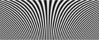
Figure 6.6. Pure frequency test card used to study resolution in the horizontal direction. The test card is sinusoidal, and the step used decreases in a linear manner from top to bottom
This MTF can also be observed qualitatively, using image i(x, y) directly; for low frequencies, the signal is transmitted in its entirety, producing high contrast. As the frequency increases, the contrast decreases, reflecting the fall in the MTF. The progressive loss of contrast clearly illustrates the evolution of the MTF.
6.1.3.2. Indicators derived from the MTF
The MTF has been used in the development of more concise indicators characterizing the resolution of a camera. The most widely used indicator is currently MTF50 (or MTF50P), which expresses resolution as the spatial frequency for which modulation is attenuated by 50 % (or to 50 % of its maximum value, in the case of MTF50P (as P = peak)) [FAR 06]. This value is used in the ISO 12233 standard [ISO 00].
The final frequency transmitted by the system may be observed at the point where contrast disappears. This corresponds to the resolution limit (or resolution power) seen above, if, for example, the contrast reduction bound is fixed at 5%.
6.1.3.3. Directionality
Note that the test card in equation [6.13] behaves similarly in terms of horizontal and vertical lines, and may be used to characterize frequencies in both directions. These measurements are well suited for analyzing the response of a matrix-based photoreceptor. However, we may also wish to consider frequencies in other directions (for example, diagonal frequencies, used in analyzing the role of the Bayer mask). For these purposes, we simply turn the test card in the required direction.
If more precise adaptation to the symmetry of optical systems is required, specific test cards may be used, such as those shown in Figure 6.7, which allow the characterization of radial frequencies (expressed using a single variable ![]() or tangential frequencies (expressed along the length of a circle of radius ρ).
or tangential frequencies (expressed along the length of a circle of radius ρ).

Figure 6.7. Two additional resolution test cards. Left: test card used to define radial frequencies; right: test card used to define tangential frequencies. These test cards may be binary or sinusoidal. The moire patterns seen on these test cards (like those in Figure 6.5) are due to aliasing phenomena at high frequencies
Methods using variable step test cards, while widely used in practice, are excessively global; this can be seen if we move the test card in the image. The contrast reduction frequency is generally higher in the center of the image than at the edges, expressing the fact that the MTF is not constant for all points in the image.
6.1.3.4. MTF and impulse response
To obtain a more local measurement, allowing us to indicate the resolution limit for all points in the image field, it is better to use the definition of the MTF based on the Fourier transformation of the impulse response, or point spread function (PSF), h(x, y).
Hence:
A first approach would be to analyze an image of a scene made up of very fine points. Let δ(x, y) denote the Dirac pulse:
and:
Isolating each source point, then readjusting and summing the images formed in this way, we obtain the image ![]() , where hk
, where hk
represents the image of source point k brought into the center of the field. From this, we may deduce an estimation of the transfer function:
This method is unfortunately highly sensitive to noise, as we see when analyzing the signal noise ratio. The results it produces are, therefore, generally mediocre. However, it is used in cases where test cards cannot easily be placed into the scene, or when other, better structures are not available. For example, this is the case in astronomy (which involves very large number of punctual sources) and microscopy.
One means of improving the measurement of the impulse response is to use a line as the source image ol. This line is taken to be oriented in direction y. The integral of the image il obtained in this direction gives a unidimensional signal, which is a direct measurement of the impulse response in the direction perpendicular to the straight line.
6.1.3.5. MTF measurement in practice
However, the gains in terms of signal noise ratio are not particularly significant, and the step edge approach is generally preferred.
In this approach, the observed object ose is made up of two highly contrasting areas, separated by a linear border. The image obtained, ose integrated in the direction of the contour, is thus the integral of the impulse response in the direction perpendicular to the contour:
and:
This is the most widespread method. The test card ose(x,y) generally includes step edges in two orthogonal directions, often at several points in the field (producing a checkerboard test card). This allows us to determine the two components h(x, 0) and h(0, y) of the impulse response at each of these points, then, by rotating the test card, in any desired direction θ.
Note that the step edge method presents the advantage of being relatively easy to use on natural images, which often contain contours of this type; this property is valuable when no sensor is available for calibration purposes (a case encountered in mobile robotics or satellite imaging).
6.1.3.6. Advanced test cards
Several techniques have improved the line-based impulse response measurement approach, refining the test card in order to give a more precise estimation of the MTF. The Joshi test card, for example, uses circular profiles in order to take account of the potential anisotropy of the sensor [JOS 08].
Other approaches involve inverting the image formation equation for a known image, but based on random motifs; theoretically, this produces a flat spectrum. The spectrum of the obtained image may then be simply normalized in order to obtain the desired MTF. Delbracio [DEL 13], for example, showed that the precision of all MTF measurements is limited by a bound associated with the sensor (essentially due to the effects of noise). The author proposes a test card and a protocol designed to come as close as possible to this bound (see Figure 6.8).

Figure 6.8. Two examples of test cards used to measure the resolution of imaging systems. Left: the random test card developed by M. Delbracio-Bentancor. Right: the DxO dead leaf test card, taken from [ALV 99], used to characterize texture preservation. The spectrum frequency reduction is expressed in 1/u2
A completely different approach proposes the use of test cards with a random pattern of dead leaves, presenting a polynomial power density spectrum across the full spectrum. These patterns have the advantage of being invariant, not only in translation, rotation and with dynamic changes, but also for changes of scale, due to their fractal properties [GOU 07, CAO 10a, MCE 10]. These test cards currently give the best performance for global estimation of the impulse response. The measurements they provide are only weakly subject to the effects of sharpness amplification techniques, which we will discuss in detail later.
To a certain extent, the resolution problem may be considered to be fully explained using knowledge of the MTF at various points of the image field for all focal distances, apertures and focusing distances, as this information contains all of the material required in order to predict an image for any observed scene. However, this information is bulky and complex, and does not allow us to predict, in simple terms, the way in which this image will be “seen” by an observer. We, therefore, need to consider whether it is better to concentrate on reliable reproduction of low frequencies, to the detriment of higher frequencies, or vice versa.
6.1.4. Sharpness
The term “sharpness” is used by photographers to express the quality of frequency content, referring to good representation of fine details, alongside good levels of image resolution. However, this notion does not translate into a measurement which can be applied to an image, and remains a specialist concept, used, for example, to classify multiple photographs of the same scene taken using different parameters. Generally, an image taken with a medium aperture (for example, 5.6 or 8) often presents higher levels of sharpness than those taken with a wider aperture (involving, a priori, less diffraction error) or a narrower aperture (with greater depth of field). Sharpness is, therefore, a subjective quality, which, in practice, takes the form of better preservation (less damping) of high frequencies in areas of interest.
Using a given MTF image, it is relatively easy to modify the spatial frequencies carrying these useful data, forcing sharpness beyond that which could be obtained using an ideal system. This type of operation is widespread in photography, and began to be used even before the introduction of digital image processing techniques.
6.1.5. Acutance
Acutance, while not universally used, provides a solid foundation for the sharpness criterion as long as care is taken to establish precise observation conditions.
6.1.5.1. Sensitivity to spatial contrast
In the specific situation where we are able to define both the observation distance, the luminosity of the image and the luminosity of the lighting, the average sensitivity of the human visual system to the frequency content of an image is well known. This information is summarized [LEG 68, SAA 03] by the spatial contrast sensitivity function (SCSF).
This function is determined experimentally, proposing a variety of visual equalization tasks to observers, using charts with varying contrast and frequency. The curves obtained in this way present significant variations depending on the specific task and stimulus used [MAN 74]. When evaluating image quality, the model proposed by Mannos and Sakrison (Figure 6.9, left) is generally used; this is described by the following empirical formula:
Frequency uθ is expressed in cycles per degree, and the index θ reflects the fact that the human visual system is not isotropic, and is more sensitive to horizontal and vertical orientations (Figure 6.9, right), according to the formula [DAL 90]:

Figure 6.9. Left: curve showing the sensitivity of the human visual system to spatial frequencies in a horizontal direction, based on [MAN 74]. The frequencies are expressed in cycles per degree. The curve has been normalized so that the maximum has a value of 1 at eight cycles per degree. Depending on observation conditions, the same image may be perceived very different; on a television with a 1 m screen observed from a distance of 1.5 m, for example, we are able to distinguish 150 pixels per degree, whereas on a computer screen observed from a distance of 60 cm we only perceive 40 pixels per degree. Right: effect of test card orientation on the perception of spatial frequencies: a frequency oriented at 45°has the same apparent contrast as a horizontal or vertical frequency which is 1.45 times higher
6.1.5.2. Acutance
This quantity takes account of both the SCSF and the MTF, used to give a single figure qualifying the capacity of an image to transmit fine details, useful for image formation by a user in specific observation conditions:
Thus, for a fixed resolution, the acutance measure gives a greater weighting to frequencies in the high-sensitivity zone of the human eye, based on specific observation conditions. The acutance of an image will differ depending on whether it is observed on a cinema screen, a television or a computer; this corresponds to our practical experience of image quality.
It has been noted that the acutance, determined using a single MTF, only characterizes the center of an image; certain researchers have recommended the use of a linear combination of acutances at a variety of points in the image. However, this refinement is not sufficient to compensate for all of the shortcomings of acutance as a measure of quality; these limitations will be described below.
6.1.5.3. Limitations of acutance:
The notion of acutance appears to be based on a solid experimental foundation (measured MTF) and to take account of the human visual system (SCSF); however, it has not been generalized. This is due to the fact that acutance is a particularly fragile measure, easy to modify using artificial means and does not always reflect the perceived quality of an image.
To increase acutance, we begin by exploiting the high sensitivity of image sharpness at certain frequencies. It is easy to produce very high acutance levels in any image by magnifying these frequencies, even if the scene does not naturally contain details in the observer’s high-frequency sensitivity zone. This amplification approach essentially affects noise levels, decreasing the signal-to-noise ratio. While the acutance level increases, the resulting subjective quality decreases.
Moreover, certain details which are amplified by the improvement process may be of secondary importance for quality perception, and their accentuation may even be undesirable as they conceal more attractive properties. Professional photographers are particularly attentive to this issue, and make use of all attributes of a photo (lighting, focus, etc.) in order to retain only the esthetically relevant elements of a scene. Increasing the acutance greatly reduces the accuracy of the representation of a scene.

Figure 6.10. Acutance amplification by unsharp masking (USM). The image on the left is the original; the two images on the right have the same resolution, but have been subjected to increasing amplification of
the mean frequencies
Acutance is nevertheless a highly useful quality component, and experience shows us that careful application of acutance amplification can result in quality gains. This is illustrated in Figures 6.10. Moreover, the property has long been used in film photography, and sophisticated, complex methods6 have been developed to achieve this goal, notably unsharp masking.
6.1.5.4. Unsharp masking
Unsharp masking generally uses a direct combination of pixels around a given point in order to produce moderate amplification of high frequencies in an image. Unsharp masking reinforces image contours, increases the visibility of details and increases legibility, but to the detriment of fidelity. Moreover, it also increases noise, resulting in the appearance of unwanted details in the image; these are generally interpreted as sharpness, but can prove problematic.
Unsharp masking is a two-step process. We begin by evaluating a low-pass filtered version ilp(x, y) of the image i(x, y), before removing a portion of this filtered image from the original image, and increasing the contrast as required in order to use the full dynamic range. Frequencies not affected by the low-pass filter are, therefore, subject to relative amplification.
The first stage can be carried out using a Gaussian filter, for example, generally in the image plane; in the Fourier plane, this filter is expressed by the formula:
where parameter σ sets the range of the frequencies to be dampened. This parameter is generally determined by the user. This stage consists of calculating the image after unsharp masking iusm:
where parameter α is used to control image filtering levels, and coefficient γ allows us to control contrast through best use of the available dynamic.
In many applications, formula [6.26] is applied exclusively to contour pixels in order to avoid excessive increases in noise. This is done using a third parameter, δusm, which establishes the minimum difference between a pixel and its neighbors. If no difference greater than δusm is found, then the pixel will not be treated.
A more direct approach involves convolution in the image plane via the use of a carefully selected mask, or via iterative techniques based on diffusion equations.
Many cameras systematically apply unsharp masking during image acquisition, often with different parameters depending on the selected capture mode. Photographs of landscapes or sporting events are, therefore, treated using more stringent parameters than portraits, for example. Furthermore, the images produced by low-cost cameras are often subject to aggressive treatments, which improve the perception of the image on the camera’s own small screen and hide resolution or focusing errors; however, the quality of printed versions of these images is limited. More complex cameras allow users to adjust unsharp masking settings; in this case, unsharp masking is only applied to images in JPEG and RAW (these are the objects of Chapter 8).
Note that unsharp masking should implicitly take account of observation conditions. It is, therefore, most useful in the context of postprocessing, and it is better to use the unsharp masking tools included in image treatment software than to allow indiscriminate application during image capture.

Figure 6.11. Unsharp masking: power density spectrum of an image (logarithmic scale), before and after filtering, using two different types of unsharp masking filters. Right: transfer functions of the two filters, in the form [1 – α exp(−au2)], multiplied by a function  , which cancels out at the limits of the bandwidth in order to remove aliasing effects. For a color version of this figure, see www.iste.co.uk/maitre/pixel.zip
6.2. Global image quality assessment
Over the last 50 years, the scientific community has used these quality criteria, along with others discussed below, in attempts to qualify image quality (and not the quality of photographic systems, as we would wish). This work has led to the creation of a subdomain of image processing, often known as image quality assessment (IQA) and to extensive publications. The role of IQA is to provide reliable tools for predicting the visual quality of images, applicable to a wide variety of applications, from compression to coding, onboard robotic systems, site surveillance, target detection and tracking in industrial or defense applications, image watermarking for copyright protection purposes, etc. A thorough review of work carried out in this subject is available in [CHA 13].
Work on IQA has notably resulted in the creation of an International Telecommunications Union recommendation (current version ITU-R BT.500, 2013 [ITU 13]) which sets out the conditions for establishing a subjective image quality score for television pictures7; this recommendation may also be applied to stationary images.
The recommendation uses two complementary five-level scales, one representing quality, the other representing impairments. The first is essentially used for no-reference evaluations, while the second is used for evaluations based on a reference (see Table 6.1).
Table 6.1. Table showing the quality and impairment scales put forward in ITU6R BT 500-13, [ITU 13]
| Quality scale | Impairment scale | ||
|---|---|---|---|
| 5 | Excellent | 5 | Imperceptible |
| 4 | Good | 4 | Perceptible, but not annoying |
| 3 | Fair | 3 | Slightly annoying |
| 2 | Poor | 2 | Annoying |
| 1 | Bad | 1 | Very annoying |
The aim of this project is thus slightly different from that which we have considered so far, as no attempt is made to define quality attributes. We also note that these scales give little consideration to images of very high quality, such as those obtained in photography, which generally only use levels 4 and 5.
Finally, note that, while the final evaluation is global (“excellent”, for example), the ITU approach, like most of those examined below, is based on the collection of a quantity of local information (such as perceptible impairments) which are then aggregated into a single criterion. This pooling operation is sometimes subject to explicit formulation, but on other occasions, as in the ITU recommendation, remains unformalized.
We will now present a number of methods which operate based on the use of a real reference image (rather than a test card, as in previous cases), before considering some examples of no-reference methods8. As we will see, most work in this domain is based on analysis of the human visual system, and methods generally attempt to reproduce biological mechanisms. It is now possible to design evaluation systems which accurately reproduce this system of perception. While these methods have yet to provide an operational solution to the problem of quality estimation in photography, they have produced promising results, and provide an interesting formal framework, which we will discuss below.
6.2.1. Reference-based evaluations
A family of measures exists based on the Euclidean distance between two images: ![]() the image under test and
the image under test and ![]() the reference image, or, in an equivalent manner, between their cross-correlation functions, whether or not these are normalized or centered. The universal quality index (UQI) criterion [WAN 02] is expressed as:
the reference image, or, in an equivalent manner, between their cross-correlation functions, whether or not these are normalized or centered. The universal quality index (UQI) criterion [WAN 02] is expressed as:
using mean values ![]() and
and ![]() variances
variances ![]() and
and ![]() and the centered cross-correlation:
and the centered cross-correlation:
This criterion takes values between -1 and 1. It has a value of 1 if the images are proportional. The UQI uses a single term to express three impairment types: loss of correlation, loss of contrast and distortion of luminosity. It has been widely revised and extended in recent years; the structural similarity (SSIM) criterion, for example, adds two constants to formula [6.27]:
These constants, ![]() and
and ![]() , are expressed empirically as a function of image dynamics, and result in a regularization of the criterion in uniform zones. They typically take values between 2 and 50, and
, are expressed empirically as a function of image dynamics, and result in a regularization of the criterion in uniform zones. They typically take values between 2 and 50, and ![]() . Other authors have extended the UQI to color images. However, the cross-correlation criterion remains rather crude, barely more satisfactory than the signal-to-noise ratio, and its use is extremely limited outside the field of coding applications. Other approaches, which replace this criterion by cross-information measures [SHE 06] or distances in a singular value decomposition (SVD) [SHN 06], are little better.
. Other authors have extended the UQI to color images. However, the cross-correlation criterion remains rather crude, barely more satisfactory than the signal-to-noise ratio, and its use is extremely limited outside the field of coding applications. Other approaches, which replace this criterion by cross-information measures [SHE 06] or distances in a singular value decomposition (SVD) [SHN 06], are little better.
Many researchers have noted that indiscriminate summing of a local measure is not particularly compatible with human judgments, which are particularly focused on certain structures or zones of specific interest to the observer, often due to their semantic content. For this reason, an additional step may be added before measuring the difference between the reference and test images, consisting of selecting or amplifying zones of interest. The criterion used (SNR, UQI or SSIM) is then weighted using this visibility, or salience, map before summing. The construction of these maps has been widely discussed, with methods based on the use of perceptual methods such as the SCSF (equation [6.22]), on the use of information theory to identify zones of interest or on empirical selection of zones featuring high contrasts and contours. For example, Wang [WAN 11] uses a statistical image model based on a mixture of multiscale Gaussians. Shared information from the reference and test images is calculated locally, and then distributed using a multiscale representation to describe the significance of each difference. Unsurprisingly, in this context, it is generally best to amplify the importance of high-contrast zones within the image, and of zones where there is a large difference between the test and reference images.
A number of authors have modeled these human processes, and attempted to use statistical methods to “learn” them. One example of this type of approach is the machine learning-based image quality measure (MLIQM) algorithm [CHA 12b]. Using the many known criteria involved in perceptual evaluation, the MLIQM algorithm does not, however, involve a fully developed model of human vision. It makes use of a wide variety of measures, including both spatial properties (13 primitives) and spectral properties (12 primitives) of test and reference images. The spatial primitives, which essentially reflect the structures in the image, are calculated on multiple scales using distortion maps, each reduced to a single score. The frequency primitives are calculated over three levels and four orientations; as with the structural coefficients, they are expressed in the form of a single final score. The vector of the structural and spectral primitives is then classified using a support vector machine (SVM), which has previously been “trained” using a range of examples. The results obtained in this way are converted into a score, from 5 to 1 on the ITU scale (see above); these scores present excellent correlation with the scores given by human observers for reference databases.
The visual SNR (VSNR) criterion [CHA 07b] is more complex, being based on richer psychovisual bases, and involves a two-step approach. First, it detects a variety of potential impairments, using mechanisms similar to the first levels of human vision. Distortions between the test and reference images are calculated, band-by-band, after decomposing the image into frequency bands using one-octave steps. At the same time, visibility thresholds are established for each band. This allows us to carry out the second stage, identifying the perceptible components of differences between the image under test and the reference. These components are then subjected to empirical priority rules for frequency bands (low frequencies have a higher weighting only if the structures including the differences are large). When compared to human judgments across a wide base of images and impairments, this criterion presents strong prediction capacities; however, the implementation is relatively heavy.
6.2.2. No-reference evaluation
No-reference methods for image quality evaluation have also been the subject of extensive research [FER 09, HEM 10]. A priori, this type of approach is better suited to the evaluation of photographic equipment; however, as we will see, examples of this type are not yet fully operational. Most of the proposed methods consider two specific aspects of quality: contour definition, on the one hand, and the absence of noise, on the other hand. Other approaches focus specifically on compression-related impairments: JPEG and JPEG2000. These are less relevant to our specific context. After discussing contour sharpness and the presence of noise, we will consider the way in which the statistics of natural scenes may be used, before considering a more advanced method based on phase coherency.
6.2.2.1. Noise measurement
Noise b is traditionally evaluated by studying the neighborhood of the origin of an image’s autocorrelation function. Its power is often measured by using the excess at the origin of this function compared to the analytical extension of the surrounding values. Writing the noised image in the form
![]() , and considering that the unnoised image has a correlation Ci(x, y), the noise is impulsive and not correlated to the signal, the autocorrelation of the noised image becomes:
, and considering that the unnoised image has a correlation Ci(x, y), the noise is impulsive and not correlated to the signal, the autocorrelation of the noised image becomes:
Well-verified models of Ci show the exponential reduction either in terms of x and y, or, better, in ![]() , taking account of the possibility
, taking account of the possibility
of anisotropy, and allow us to deduce σb by studying Cib.
6.2.2.2. Contour sharpness
The sharpness of contours is an issue familiar to all photographers, and is the reason for the inclusion of a specific element, the autofocus system (these elements will be discussed in section 9.5.2), in photographic equipment. However, the approach taken may differ. Focus search features which act on image quality (this is not universal: other elements operate using telemetric distance measurement via acoustic waves, or using stygometry, i.e. by matching two images taken from slightly different angles), only use small portions of the image (either in the center of the pupil, or scattered across the field, but in fixed positions determined by the manufacturer) in order to obtain measures. These features allow dynamic focus variation in order to explore a relatively extended space and determine the best position. The criteria used to define the best position are very simple: signal variance, or the cumulative norm of the gradients. Simplicity is essential in order for the feature to remain reactive.
Using the IQA approaches described here, however, an exhaustive search may be carried out over the whole field, or we may look for the most relevant zones to use for this measure. However, we only have an image to use in order to decide whether or not a point is good. As we are not limited to realtime operation, longer calculation processes may be used in these cases. We, therefore, wish to characterize contour sharpness at global level, across the whole image. To do this, images are often divided into smaller cells (of a few hundred pixels), and the calculation is carried out separately for each cell. This process generally involves three steps:
- – The first step determines whether or not a contour is present in cell k. If no contour is present, then the cell is left aside. Otherwise, the position of this contour is determined using local gradient measures.
- – We then define the width ψ(k) of the contour, measuring its extent, the length of the line with the greatest slope.
- – Finally, a global quality score is deduced from the various measurements obtained, allocating weightings which may be based on visual perception rules (for example, using salience maps, or leaving aside measurements lying below a specified visibility threshold).
Local measures may then be combined in the following manner [FER 09]: we begin by defining a just noticeable blur (JNB) threshold ψJNB(k), which is a function of the variance and contrast of cell Ck. The probability of finding a single contour of width ψ within a window k is given by the psychometric function9:
Variable β is determined experimentally based on image dynamics. In the presence of multiple independent contours in a cell, the probability of detection will be:

and the consolidated measure for the whole image i is expressed:
Variable D = — 1/βlog[1 — Proba(i)] and the number l of treated cells are then used to define a sharpness index, S = l/D.
6.2.2.3. Statistics of natural scenes
The use of statistics measured using a variety of natural scenes is one way of compensating for the lack of references in evaluating image quality. However, few statistics are sufficiently representative to allow their use in this role [SIM 01, TOR 03].
The natural image quality evaluator [MIT 13] (NIQE)method uses statistics based on image amplitude [RUD 94]: an intensity ![]() given by the intensity
given by the intensity ![]() of each pixel, corrected using a weighted bias
of each pixel, corrected using a weighted bias ![]() and weighted variance
and weighted variance ![]() :
:
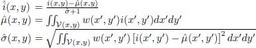
where V(x, y) represents a small circular domain around the point (x, y), and w(x, y) is a Gaussian centered on this point. These same elements, known as mean subtracted, contrast normalized (MSCN) coefficients, have been used in a number of other methods, such as the blind/referenceless image spatial quality evaluator (BRISQUE) [MIT 12].
The most robust properties, however, are those based on spectral properties.
The distortion identification-based image verity and integrity evaluation (DIIVINE) [MOO 11] method, for example, uses models of wavelet coefficients of multiscale decompositions of an image. These coefficients are particularly interesting in the context of image coding. The marginal and joint statistics of these coefficients have been shown to be represented successfully using Gaussian mixtures.
The parameters of these models are learned from original images, and then from images subjected to a variety of impairments: blurring, added noise, compression of various types and transmission over lossy channels. Applied to an unknown image, the DIIVINE method begins by determining whether or not an image is defective, and if so, what type of impairment is present; it then assigns a quality score which is specific to this impairment type. This procedure has produced satisfactory results over relatively varied databases, but the full procedure remains cumbersome, as it requires multiple successive normalizations.
6.2.2.4. Global phase coherence
Instead of measuring contour spread, it is possible to consider the inverse quantity, i.e. the image gradient and its distribution within the image.
This problem has been addressed in a more analytical manner by examining the way in which transitions in the normal direction of the contour occur, and, more precisely, by studying the global phase coherence [LEC 15]. The underlying idea is based on the fact that a well-focused image is highly sensitive to noise disturbance and to phase modifications of the various frequencies making up the image. These abrupt variations can be measured using particular functions derived specifically for this purpose:
– global phase coherence G, expressed as a function of the probability that a global energy measure (the total variation, TV) of an image iφ, subject to random phase noise will be lower than that of the original image i:
where the total variation of a function f(x) is expressed as:
and that of an image i(x, y) depending on two indices is expressed as:
However, this criterion can only be calculated via a cumbersome simulation process, with random drawings of a number of phase realizations;
- – the sharpness index, in which the random phase disturbing i is replaced by convolution by a white noise w:
where ![]() and μ and σ2 are the expectation and
and μ and σ2 are the expectation and
variance of TV(i * w);
- – the simplified sharpness index S, deduced from the term given above by replacing σ with σ′; the expression of the latter term is more compact, and is obtained by calculating the second derivatives ixx, iyy and ixy and the first derivatives ix and iy of i:
While the complexity of these criteria is greatly decreased, they behave, experimentally, in a very similar manner as a function of the blur present in the image. Although they are well suited to monitoring the treatments applied to images (such as deconvolution), these criteria suffer from an absence of standardization, making them unsuitable for our application.
6.2.3. Perception model evaluation
A number of the mechanisms involved in image perception have already been described in this book. These relate to photometric sensitivity (section 4.2.1) or spectrometric sensitivity (section 5.1.2), the persistence of the impression of color and the effects of spatial masking (section 5.3). In addition to these mechanisms, we need to consider multiscale processing, which allows observers to examine scenes in a hierarchical manner, either by considering the general distribution of wide bands, or by considering fine local details, via a continuum of descriptions of variable resolution. Wavelet pyramid, Gaussian pyramid or radial filter decompositions provide a good representation of this property.
Methods based on perception models are particularly useful for expressing degradations which take place during image acquisition. They presume the existence of an “ideal” image, to which the acquired image is compared. The reference image and the image being analyzed are processed in parallel using a “perception model”, which is supposed to convert these two images into stimulus fields similar to those delivered by the visual system (Figure 6.12). As we have seen, multiple fields exist, as the cortical columns in the visual system break down images by chromatic content, orientation and spatial frequency. These stimulus fields are then compared, point-by-point, using a metric (which is itself perceptive) to determine what users will actually perceive as being different, and what will remain undetected. Taking account of all these perceived differences, with careful application of weighting, we then assign a score; this may be considered to be the perceived difference between the two images, and seen as a loss of image “quality”.
6.2.3.1. Expressing perceptual difference
Chandler [CHA 13] provides a relatively general form of the simulated response of a visual neurone to a set of stimuli, suitable for use in measuring the quality of an image in relation to a reference. This method will be described below, using the same notation as elsewhere in this book. First, image i(x) at the current point x = (x, y) is decomposed into a channel ![]() using three types of information:
using three types of information:
- – the spatial orientation, denoted using variable θ;
- – the spatial frequency, denoted by u;
- – the chromatic channel10, obtained by combining signals L, M and S (section 5.1.2), denoted by χ.
Channel ![]() is weighted using the SCSF, φu,θ (equation [6.22]). It is raised to a power p, expressing the nonlinear nature of the neurone, and normalized using a term which reflects the inhibiting effect of neighboring neurones. This term includes a saturation term b and summing across the neurones S connected to the neurone under study. An exponent q (generally lower than p) is used to express the nonlinear nature of the inhibiting pathway, and a gain g is applied to the whole term. The response
is weighted using the SCSF, φu,θ (equation [6.22]). It is raised to a power p, expressing the nonlinear nature of the neurone, and normalized using a term which reflects the inhibiting effect of neighboring neurones. This term includes a saturation term b and summing across the neurones S connected to the neurone under study. An exponent q (generally lower than p) is used to express the nonlinear nature of the inhibiting pathway, and a gain g is applied to the whole term. The response ![]() from the channel is thus expressed:
from the channel is thus expressed:
The parameters governing this equation are generally determined by experimenting with known signals, and are adapted for digital images using classic simplifications (for example, frequencies are converted into octaves using wavelet decompositions, orientations are reduced to horizontal, vertical and diagonal directions, the domain S is approximated using eight neighbors of the central pixel and the variables covered by χ are either the red, green and blue channels, or the red/green and yellow/blue antagonisms).

Figure 6.12. Image quality assessment based on a reference image and a perception model
6.2.3.2. Expression of quality
The model given by equation [6.40], applied to the image under treatment and the reference image, provides us with signals, one for the image under treatment, ![]() , the other for the reference image
, the other for the reference image ![]() .
.
In its simplest formulation, the distortion at point xo is defined using the differences between these two values. Based on the hypothesis that the perceptual channels are independent, which is relatively well verified, we obtain:

Other formulations make use of psychovisual considerations in order to avoid characterizing differences for all points, concentrating instead on smaller areas. Using a simple model, this difference, compared to a threshold, allows us to create a map of perceptible differences. Integrated using a logistical model, this gives us a single quality score, only valid for the specific image in question. Averaged over a large number of images, this score enables us to characterize specific equipment in specific image capture conditions.
Some examples of general models for image quality assessment are given in [WAT 97, BRA 99, LEC 03, LAR 10].
However, work on human perception has essentially resulted in the creation of quality indices for specific applications, which only take account of a limited number of distortions. A wide variety of indices of this type exist [CHA 13]: noise measurement, structural differences, contour thickening, etc.
6.3. Information capacity
Another way of approaching the notion of image quality is to use vocabulary and techniques from the field of information theory, as suggested by Shannon. In this approach, the camera is considered as a channel, subject to the laws of physics and technology, and governed by parameters (aperture, exposure, focus and sensitivity) fixed by the user. This channel is used to transmit a degraded version i(x,y) of a scene o(x,y). The aim in using information theory is to measure message degradation resulting from the transmission process, to define upper performance limits which we may hope to attain in an ideal situation, and to suggest parameter values to optimize performance.
This approach was first explored in the 1960s by physicists, notably for image processing applications in the field of astronomy, but rapidly encountered problems due to the limitations of analog signals. The discrete representation of images produced by digital sensors offers new possibilities, complementary to those examined above. An information-based approach was put forward in [TIS 08] to respond to a key question posed by users when buying photographic equipment: does an increase in sensor resolution improve image quality?
6.3.1. The number of degrees of freedom
Digital images are coded using n bits, and each pixel (i, j) in the image is subject to a noise, with an average value which will be presumed to be zero (this will be verified in Chapter 7), and a standard deviation σ(i,j) which may vary within the image, for example due to the different gains applied to different sites (see section 3.2.3), to aberrations (section 2.8) or to vignetting (section 2.8.4.1). We thus have ν(i, j) independent levels within (i, j):
In this formula, the term max(1, σ(i,j)) expresses the fact that, if the noise σ is less than a level of gray, then all of the 2n levels are independent. If the dependence of the noise as a function of the signal is known exactly, we can use the precise number of effective levels νe (see equation [6.5]).
In total, the image, therefore, presents ν1 degrees of freedom:
if all sites are independent [FRI 68]; ν1 is also known as Shannon’s number.
This expression of the number of degrees of freedom, in this case measured at the sensor output point, may be compared to the degrees of freedom of the incident wave providing sensor input.
This number is given by the surface of the sensor S divided by the angular resolution of the lens dΩ (Ω = solid angle of the lens). In the case of a circular aperture of diameter D and focal distance f, and with a wavelength λ, the angular resolution is given by dΩc = (D/λf)2 in the coherent case and dΩi = (D/2λf)2 in the case of incoherent photographic imaging; the latter case will be considered here [FRA 55, FRA 69]. Taking N = f/D as the aperture number, in the incoherent case11, we obtain:
Approximating the two estimations of the number of degrees of freedom made before and after detection by the photodetector, we obtain the limit case where the two terms ν1 and ν2 are equal. This arises in situations where the sensor and lens are able to transmit the same quantity of information, i.e. the two elements are ideally suited. This gives us:
In the case where all pixels have an identical noise of variance σ ≤ 1, and considering a sensor of which the whole surface contributes to the signal (with no space set aside for electronic elements – Figure 3.7), and for which, therefore, S = nxnylxly, we obtain the following relationship between the number of useful bits in image n and the aperture number of lens N:

Figure 6.13. Relationship between the number of bits assigned to each pixel and the f-number of the optical element, in the case where the sensor and lens match perfectly, i.e. the sensor transmits exactly the same number of degrees of freedom recognized by the lens. Above these curves, the sensor is overdimensioned; below the curves, the sensor is underdimensioned. Results are shown for a green wavelength (500 nm) and three dimensions of photosites
Two different regimes are shown in Figure 6.13: below the curves, the lens measures more degrees of freedom than the sensor is able to transmit. The camera is thus limited by the sensor. Above the curves, on the other hand, the sensor transmits more signals than the lens is able to send. These signals are, therefore, not independent, as the lens is not sufficiently powerful, and the sensor is underexploited.
In the highly simplified form used here, information theory indicates what each system is capable or incapable of in an ideal situation. Here, we have considered that the lens, focus and signal conversion process are entirely flawless. However, there are many reasons why pixels from neighboring sites may not be independent; they are often correlated, either during the formation of the image on the sensor, and beyond the limiting optical resolution considered here – focusing errors, aberrations, parasitic reflection, electronic diaphony between pixels, etc. – or during reconstruction (demosaicing, antialiasing, low-pass filtering, etc.) – or during coding (e.g. the resetting of high frequencies when using JPEG). Similarly, the operational lighting conditions we have considered allow us to maintain noise below one gray level, whatever architecture is used, and, more specifically, for any size of photosite. The hypotheses underpinning this reasoning will be considered in greater detail later. Note, finally, that information theory gives us no indications as to the way in which signals should be effectively treated in order to profit fully from the number of available degrees of freedom.
6.3.1.1. Information theory and coded apertures
Approaches which take account of the number of degrees of freedom in a system have recently been applied to a new area, due to the use of coded apertures or lens matrices in the context of computational photography, which requires us to measure different quantities to those used in traditional imaging (particularly in terms of depth of field); this requires us to modify equation [6.44], [STE 04, LIA 08].
6.3.1.2. Color images
The case of color images is more complex.
From a physical perspective, examining the way in which various wavelengths transmit various types of information, we first need to examine the role of sources, then that of objects in a scene. The degree of independence of the various wavelengths emitted is dependent on the emission type (thermal, fluorescent, etc.). The emission bands are generally large and strongly correlated, with few narrow spectral lines (this point is discussed in section 4.1.2), meaning that the various wavelengths are only weakly independent. This enables us to carry out white balancing using a very small number of measures (see section 5.3).
However, the media through which waves are transmitted (air, glass, water, etc.) and those involved in reflecting light lead to the creation of significant distinctions within spectral bands, increasing the level of diversity between frequencies. The phenomena governing the complexity of the received spectrum are, essentially, those discussed in section 5.1.1, and are highly dependent on the type of scene being photographed; each case needs to be studied individually in order to determine the quantity of information carried by the incident wave. Note that a number of studies have shown that representations using between 8 and 20 channels have proved entirely satisfactory for spectral representation of chromatically complex scenes [TRU 00, RIB 03].
Leaving aside these physical considerations, we will now return to an approach based on subjective quality, which uses the visual trivariance of human observers to quantify the information carried by the luminous flux.
In this approach, spectral continuity is reduced to three channels, R, G and B. For each channel, the calculations made above may be applied, but it is then necessary to take account of interchannel correlation, and of noise on a channel-by-channel basis.
The procedure consists of representing the image in a colorimetric perceptual space (see section 5.2.4) which is as universal as possible, in which we measure the degrees of freedom in each channel, using a procedure similar to that described above. To do this, we may follow the recommendations set out in standard [ISO 06b]. The approach used to determine the number of degrees of freedom is set out in [CAO 10b]; it takes place following white balancing, which corrects issues associated with lighting and with the sensor, and after correction of chromatic distortions due to the sensor (for example, by minimizing the CIELab measure between a known test card and the measured values for the illuminant in question). We then calculate the covariance matrix of the noise in the space sRGB. From this, we determine three specific values of σk for k = 1, 2, 3. Ratio 2n/(max(1, σ(i,j))) from equation [6.42] is then replaced by the number of independent colors available to pixel (i,j), and equation [6.42]:
Equation [6.44] then needs to be modified to take account of the RGB spectrum. For this, we use three primaries of the sRGB standard, λB = 0.460 nm, λV = 0.540 nm and λR = 0.640 nm, adding a factor of 2 to the denominator for the green channel and a factor of 4 for the red and blue channels, due to the geometry of the Bayer matrix. The maximum number of degrees of freedom perceived by the photographic objective is then obtained using equation [6.44], which gives:
For a sensor of size S = lx × ly (expressed in micrometers) and an f-number N, this becomes:
6.3.1.3. Unified formulation of the frequency space
An integral space-time approach, using the Wigner–Ville transformation, provides an elegant expression [LOH 96] of the diversity of descriptions of image f in a space with 2×2 dimensions: two dimensions are used for the space variables (x,y), and two dimensions are used for the orientation variables (μ, ν) of the incident rays:

This approach will not be used here, as it involves extensive developments which, to our knowledge, have yet to find a practical application in photography.
6.3.2. Entropy
The information theory approach to image quality introduced the number of degrees of freedom as a significant parameter in camera dimensioning. Continuing with this approach, it is possible to provide more precise figures concerning the quantity of information transmitted by the camera. This is done using the notion of entropy.
The digital images produced by a sensor can be represented well in terms of entropy, defined as the average incertitude measure carried by the image [SHA 48]. The notion of information, as defined by Hartley, is expressed as the logarithm of the probability of an event (a certain event – with a probability of 1 – provides no information, while a very unlikely event, if it does occur, provides a lot of information). The entropy of an image is expressed in bits per pixel. The image f(i,j) may be seen as a source of pixels, which are, as a first approximation, taken to be independent12, and transporting the following average quantity of information per pixel:
where p(k) expresses the probability of the level of gray k (or the triplet k = {R, G, B} in the case of a color image); this probability is estimated by measuring the frequency of occurrence of level k among the K available levels. The results of this approach are well known:
- – a priori, the entropy ε increases as the richness of the image increases at different levels;
- – maximum entropy occurs when all levels of gray are equally occupied, with a value of ε = n bits per sample if the image is coded on K = 2n bits, or ε = 3n bits per sample for a color image, coded using three channels of n bits, each represented in a uniform manner;
- – entropy is always positive, and only cancels for a uniform image (∃k:p(k) = 1);
- – entropy calculations in the image space or the frequency space following a Fourier transformation are equivalent, on the condition that the image is stationary (this is rarely the case) and observed over a domain XY which is sufficiently large that the product 4XYBxBy is much greater than 1; Bx and By represent half-bandwidths in terms of x and y.
Experience has shown that, unlike most natural signals, images do not possess a histogram model [MAI 08b], except in certain specific cases: seismic imaging, radar imaging [LOP 08], ultrasound, etc. The use of a Gaussian distribution (often applied to high-volume signals) is not justified.
6.3.2.1. Mapping
Images are often transformed by changing coordinates, for example to account for perspective or aberrations. This has an effect on the entropy. Transforming the space variables of x = (x, y) into x′ = (x′, y′) using the transformation x′ = T(x), which has an inverse transformation x = T′(x′) and a Jacobian J(x|x′), the entropy ε′(x′) of image i′(x′, y′) is expressed as a function of that image i(x, y), ε(x) using the relationship:
where Ex [u] denotes the mathematical expectation of function u.
While image entropy is maintained during translations and rotations (since J = 1), perspective projections and distortions, which are not isometric, result in changes to the entropy.
6.3.2.2. Entropy of the source image behind the camera
It is harder to define in practice. If the object space is expressed as the wavefront at the input lens, we have a continuous signal with continuous values. Definition [6.51] ceases to be applicable, and its extension from the discrete to the continuous domain poses significant mathematical difficulties (see [RIO 07] pp. 60–63, for example). In these cases, we use a formula which is specific to the continuous case, constructed using the probability density π(x), which gives us a quantity known as differential entropy13. This allows us to extend entropy properties, on the condition that we remain within continuous spaces and we do not modify the space variables:
This formula is similar to the direct expression, but does not constitute a continuous extension of this expression.
6.3.2.3. Loss of entropy
Equation [6.53] allows us to measure the loss of information from an image in the course of linear filtering ([MID 60] section 6.4). If the image has a bandwidth Bx × By and if the filter has a transfer function H(u, v) in this band, the differential equation loss to which the image is subjected in passing through this filter may be calculated in the Fourier domain (as the FT is isometric and thus conserves entropy). It is measured using:
If the logarithm is in base 2, this is expressed in bits, and if Bx and By are expressed using the interval [–1/2, 1/2], this is expressed in bit/pixel.
Note that this formula is independent of the image, and only characterizes the filter. It indicates a loss of information affecting a signal of uniform spectrum, i.e. white noise. It thus allows us to compare the effects of different filters on a family of images. Applied to a given image, we need to take account of the frequency content in order to determine the information loss affecting the filter, as, for each frequency, the image cannot lose more information than it actually possesses.
6.3.3. Information capacity in photography
Various elements contribute to the capacity of information which may be carried by an image, recorded by a camera, in specific capture conditions; these may be assembled following the approach set out in [CAO 10b]. To do this, we suppose that the incident signal has a very wide spectrum, greater than the camera resolution, and that the aperture, exposure time and sensitivity are able to cover the full image dynamic without reaching saturation.
The number of photosites, N, is the most visible and most widely-known factor. The dynamics of each pixel, expressed as a number of levels of gray n (256 or more for native-format images), or, better, as the number of effective levels ne taking account not only of the range of radiances covered by the saturated pixel (corresponding to the full well capacity of the photosite, see section 3.2.3), but also of the noise in the whole dynamic following relationship [6.5], is another key factor.
In the absence of other impairments, the maximum information capacity would be given by Cmax = neN; however, these other potential impairments need to be taken into account.
First, each pixel needs to be connected with its dynamics (which may be affected by vignetting). Vignetting is treated in different ways by different cameras. If vignetting is not taken care of by software elements, the pixel will be subject to dynamic loss (according to the law in terms of cos4 α presented in section 2.8.4). If, on the other hand, a gain is added to compensate for vignetting, then the noise level will increase (in accordance with the term gcv in equation [7.10]).
For spatially variable errors, such as chromatic and geometric aberrations, geometric transformation equation [6.52] should be applied to each pixel. These errors may also be taken into account in an approximate manner in the term expressing the noise affecting each pixel14.
These impairments reduce the number of levels of each pixel to nf (x, y) ≤ ne, and the quantity of information carried by the image becomes:
We then need to take account of the convolution-related impairments which affect pixel formation using equation [6.54]. In this case, we will consider lens diffraction and integration by the sensor (which is almost, although not entirely, invariant under translation).
Spatially invariant impairments affect all pixels, and expression [6.54] can, therefore, be applied in each case. The number nn(x, y) of bits required to code a pixel (x, y), initially having nf independent levels but affected by the transfer function H of the lens, is therefore expressed as:

The terms nf and max[0, nf + …] reflect the fact that a pixel cannot lose more information than the number of bits used to represent it permits. If the filter is perfect (H(u,v) = 1, ∀(u,v)), then nn = nf; generally, however, 0 ≤ |H| ≤ 1 and nn <nf.
Let us apply this expression to a Bayer-type sensor. First, it is likely that we will need to differentiate between the dynamics of the R, G and B signals, and use different terms nf for each, as chromatic impairments have a different effect on each channel. This is easy to carry out, and in some cases it is not necessary. The problem of sampling is more complex. As we have stated, Bx = By = 1 must be selected so as to allow expression of the integral in bits/pixel. However, the green channel is sampled using 2 pixel steps. In this case, therefore, we only retain a fourth of the spectrum, and equation [6.56] becomes:
Similarly, the red and blue channels give:

Function H is the product of two independent terms: diffraction by the lens Hf and integration at the photosite Hs.
Hs is determined based on the size of the photosite (presumed to be rectangular) alone. Let δx and δy be the dimensions of this photosite:
Hf is determined by the focal distance f and the diameter of the diaphragm D of the lens (and hence by the aperture number f/D), and is dependent on the source wavelength λ:
The maximum capacity of information carried by the green channel thus becomes:
Note that the coupling between lens diffraction and pixel dimension is reflected in the limits of the integral [6.62], as we have chosen to express the bandwidth as the inverse of the maximum frequency accepted by the photosite.
If the losses due to linear filtering are low in comparison to the number of effective levels of a pixel, and if the N pixels in an image have the same dynamics and the same noise level, this equation can be reduced to:

Similar formulas may be written for the blue and red channels. The total maximum information capacity carried by the image is:
6.3.3.1. Discussion
Equation [6.63] shows that the information capacity of the image is calculated as the product of the number of pixels and the effective number of available levels, minus the losses due to pixel integration and lens diffraction (as the integral is always negative); see Figure 6.14.
The consequences of these formulas are listed below:
- 1) If the dimension of the sensor is fixed, we may wish to increase the number of pixels, N, by reducing the size of each site. This has a number of consequences:
- - as N is a factor of the two terms of equation [6.63], the information capacity should increase proportionally;
- - however, the noise will also increase, generally following a law proportional to the surface, reducing term nf in a linear manner;

Figure 6.14. Maximum loss of entropy per pixel due to diffraction as a function of lens aperture (given by term Hf in equation [6.62]), for a detector where the dimension of the photosites is 10 times the wavelength (so approximately 5.5 μm). The horizontal line located at 0.951 bits/pixel indicates the loss of entropy associated with integration by the sensor (given by term Hs). These losses are theoretical, and can only be measured for a signal of uniform spectrum; this never occurs in the case of images
- - the integral over Hs will remain unchanged, as the integrated function and the bounds follow the same law;
- - the integral over Hf will increase, as the bounds used for integration over the same function will be more widely spaced.
In all likelihood, the information capacity will initially increase (images will be richer in terms of detail) as the number of pixels increases, up to the point where the noise and blur become too significant.
- 2) If the number of pixels, the focal distance and aperture are fixed, but we choose to use a larger detector surface, the size of each photosite will increase, hence:
- - the number of effective levels will increase, as the available dynamic (fixed by the full well capacity) will increase and the noise (fixed, broadly speaking, by the number of electrons used) will decrease;
- - the integral over Hs will increase considerably (fine details will disappear due to the integration over larger photosites), but the total observed field will increase (the image will no longer be the same, as the former version only covered a small part of that which is contained in the new version);
- - the integral over Hf will decrease, as Hf will be integrated between much closer bounds (the diffraction figure for each photosite will be negligible).
The scene will, therefore, be different, with fewer fine details but a greater field. Each pixel will be richer in terms of information, and the contrast will be better; the signal will be subject to little noise, and the image quality should appear to be better, as long as vignetting and aberration issues, which will be more significant, are correctly controlled.
- 3) If we fix the number of pixels and use a larger detector surface, but adapt the focal distance in order to retain the same field:
- - the same conclusions as above will be reached in terms of dynamics and noise, and hence in terms of image quality;
- - this time, the integral over Hs will remain constant, expressing the fact that integration over the sensor relates to the same details in the image;
- - if we succeed in maintaining a constant aperture number, the integral over Hf will decrease, as Hf (which is solely dependent on the numeric aperture) will be integrated between closer bounds; however, lens design in these cases is more complex, as it is hard to obtain identical performances using longer focal distances. The scene will, therefore, be identical in terms of geometry, but of better quality in terms of noise and dynamics.
This discussion illustrates the compromises which need to be made by camera manufacturers. It also helps us to understand the dual aims described at the beginning of Chapter 3: first, the desire to achieve very high resolutions with a fixed sensor size, and second, as VLSI technology progresses, to obtain larger overall surfaces for quasi-constant pixel numbers. The format 24 mm × 36 mm is not particularly important in this context in terms of quality optimization, but, over the last three decades, it has come to represent a symbolic objective, connecting digital imaging with the long tradition and prestigious culture of film photography. Moreover, the use of this format allows us to continue to use older, but costly, lenses initially designed for film photography.
The notions presented above have been used in carrying out thorough and objective studies on commercial hardware. In [CAO 10b], for example, the authors determined optimal usage conditions for a number of widely available camera models (body and lens) in specific lighting conditions and with specific exposure times, chosen to reflect typical use, and taking account of particularities in terms of sensitivity, electronic noise, sensor dimensions, numbers of photosites, lens aperture, geometric and chromatic aberrations, and vignetting. The recommendations given in this work allow us to assign scores to the performance of individual cameras, and to determine ISO sensitivity and aperture parameters in order to obtain images with the highest possible information content in a wide range of usage conditions.
6.3.3.1.1. Remark
In older publications, the information theory approach was used to optimize the definition of photographic lenses subjected to specific constraints in order to maximize information transfer from the scene to the captor. Surprisingly, in these cases, for a given optical formulation, the best diaphragm is not that which maximizes the quality of transmitted light, i.e. an all-or-nothing model, but rather a diaphragm which somewhat apodizes the lens, i.e. damps the amplitude slightly in certain zones, in order to reduce the spread of the diffraction figure. The payoff for this reduction is a slight loss of energy [FRI 68]. This result places optimization in terms of energy (in which case the best option would be not to attenuate any frequency at all, leaving the pupil untouched) in conflict with optimization in terms of entropy (in which case, it is best to accept a certain level of energy loss in order to ensure that the impulse response will be as compact as possible).