
Appendix D. The Graphical Editing Framework (GEF)
GEF development is, without question, the most complex topic thus far—it would take an entire book to examine the GEF toolset in full. So, this appendix will only describe the structure and function of a simple (but complete) graphical editor.
Building a graphical editor involves much more than Draw2D Figures: It requires a sound knowledge of plug-ins, Model-View-Controller (MVC) architecture, JavaBean components, JFace Viewers, JFace Actions, JFace properties, and many of the classes that make up the Eclipse Workbench. Although this appendix won’t attempt to explain any of these concepts in depth, we’ll clarify how they work together in the GEF. Learning to build a graphical editor isn’t easy, but with sufficient experience, you can create powerful applications with reusable, interchangeable code.
GEF development is complicated but not impossible. How do you eat a two-ton elephant? One bite at a time.
D.1. A GEF overview
Before we go into the nuts and bolts of GEF development, it will be helpful to discuss how the machine works as a whole. A graphical editor functions by allowing a user to create a visual representation of a complex system. The editing process is performed by adding graphical elements to a container, setting their properties, and creating relationships between them. Once these elements and relationships are set, the editor must be able to persist the editor’s state in a file. Of course, this file doesn’t keep track of every color, dimension, and pixel in the editor. Instead, it contains the diagram’s information—its meaning—which has been separated from its appearance.
D.1.1. Separation of concerns theory
Not only does GEF development split information and appearance, it also requires classes for every separable aspect of the editor. That is, a GEF editor isn’t a single, monolithic application, but a combination of many small objects that communicate using standard interfaces. This modular structure makes editor code easy to replace and maintain. However, the multiplicity of parts makes the learning curve steep.
Figure D.1 shows how the MVC architecture provides a separation of concerns. The View is the easiest to understand, since it provides the component’s display. The Model aspect is more subtle; put simply, it holds the properties of the editor that can be modified by the user. These could include the size and location of the editor’s components and the presence and placement of the connections between them.
Figure D.1. MVC architecture for graphical editors
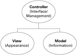
The Controller manages the component’s interaction with the rest of the GUI. It receives notice of user input and directs changes to its Model and View objects. It keeps track of connections between components and any message communication. In essence, the Controller aspect takes care of everything that isn’t related to the Model or View.
D.1.2. Separation of concerns: GEF implementation
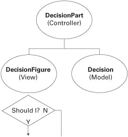
Every editable component in a GEF editor consists of three objects that provide its MVC structure. The View aspect is generally implemented as a Figure or Image. The Controller is a subclass of AbstractGraphicalEditPart. A Model class extends only Object. Figure D.2 shows the classes that will be used to create our Decision component and the naming conventions for each.
Figure D.2. The flowchart’s Decision component and the classes used to represent its Model, View, and Controller
Thankfully, we created the View aspects of the editor’s components in appendix C. We can now show how these aspects work together during editing.
Note
Although the EditPart object makes up the Controller aspect of a GEF component, the entire MVC combination is generally referred to as an EditPart, or component, or just part. Therefore, we’ll refer to the aspects described in figure D.2 collectively as a DecisionPart.
D.1.3. MVC interaction
It isn’t difficult to see how the Model, View, and Controller classes function individually. The main obstacle to understanding the GEF is dealing with their interactions, both between themselves and with the rest of the application. Even the simplest editing modification requires a complex data exchange involving Tools, Requests, EditPolicys, Commands, and PropertyChangeEvents. We’ll cover these topics in staggering detail to enable you to customize your GEF editor. But since you’re still in the first section, a quick analogy will be helpful.
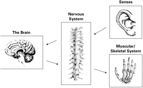
Think about how your nervous system works. Your senses perceive a stimulus and send their impression to the nervous system. The nervous system, functioning like a switchboard, updates the brain with the new information. The brain sends a response, and the nervous system extends or retracts muscles to move the skeleton. This interaction is shown in figure D.3.
Figure D.3. The GEF/nervous system analogy, part 1
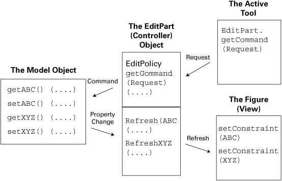
When you examine the interaction between the classes that make up GEF’s MVC architecture, the process may seem similar. When the user causes an event, a Tool object sends a Request to the selected EditPart. This EditPart uses a List of EditPolicys to create a Command that updates the Model class. When the Model changes, it fires a PropertyChangeEvent. After receiving this event, the EditPart modifies the component’s Figure (View) by invoking one of its refresh() methods. This process is shown in figure D.4.
Figure D.4. The GEF/nervous system analogy, part 2
This comparison isn’t perfect, but it provides a framework for understanding the many interfaces and objects that take part in the editing process. As we progress into greater detail, it’s easy to lose sight of the big picture; we hope you’ll keep this analogy in mind.
D.1.4. Building the flowchart editor
A graphical editor requires classes for the Model, View, and Controller aspects of each component. For the flowchart editor, the top-level (parent) component will be the Chart, which serves as the main container for the rest of the GUI elements. We’ve already created the View (ChartFigure), so we need to build a Controller (ChartPart) and a Model (Chart).
The three shapes in the editor, corresponding to the Decision, Terminator, and Process components, also require MVC triples. This means building EditParts and Model classes in addition to the Figures created in appendix C. Because these three components have so much in common, we’ll show how to create an abstract class called an Activity; then, each concrete class will extend the ActivityPart, ActivityFigure, or Activity class. In addition, we’ll show how to build an MVC triple for connections: Path, PathPart, and PathFigure.
Once we’ve finished with the individual components, we’ll explain how they communicate. This will require Commands, Requests, and EditPolicys. In addition, we’ll show how a palette adds components to the editor and how an EditorPart keeps track of the entire application.
This may seem confusing, but figure D.5, which depicts the full class hierarchy of the FlowchartProject, should help.
Figure D.5. Class structure of the FlowchartEditor application
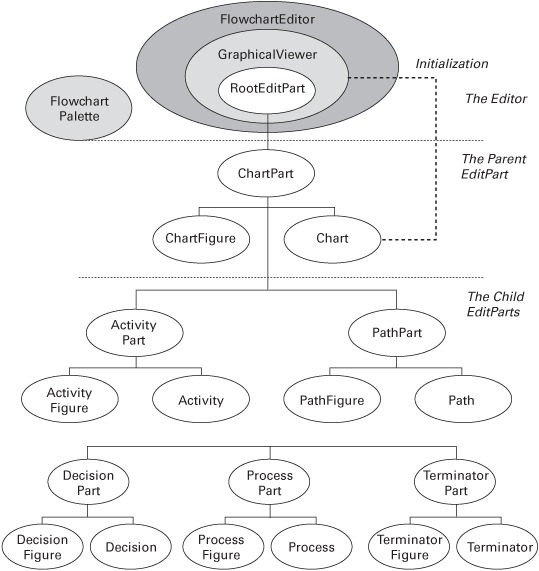
Table D.1 shows our plan of attack for building the graphical editor. Since the editing process begins with adding components from the editor’s palette, that’s where we’ll start.
Table D.1. Creating the flowchart editor using the GEF
|
Goal |
Procedure |
|
|---|---|---|
| 1 | Create Figure objects to represent elements of the flowchart (already accomplished). |
|
| 2 | Create the project, FlowchartProject. |
|
| 3 | Build the palette for the flowchart editor and the drag-and-drop ability. |
|
| 4 | Add Model classes for the Figures. |
|
| 5 | Add Commands to provide interfaces to the Model classes. |
|
| 6 | Create EditParts to combine the Model and Figure classes. |
|
| 7 | Create EditPolicys to provide manipulation of the EditPart objects. |
|
| 8 | Enable Actions to provide multiple methods of editing. |
|
| 9 | Create the overall FlowchartEditor class. | Create a FlowchartEditor class that will
|
Since this section has summarized the entire GEF development, you may feel overwhelmed. Don’t worry! All of this will be become clearer as you start programming. Let’s begin by creating the project, aptly named FlowchartProject.
D.2. Creating the FlowchartProject
Although much of this book was written for both Eclipse-based and standalone Java development, this section assumes you’re building this project using Eclipse. A user can run normal Java applications whenever he pleases, but Eclipse editors are activated only when an appropriate file is selected for editing. This means Eclipse needs to know in advance which editor should be used for a given file type. In our case, the Workbench needs to know that the flowchart editor should be activated whenever the user edits a flowchart file, designated by *.fcf. A Draw2D application won’t do the job: We need a plug-in.
To begin building this plug-in project, follow these steps:
1. Select File->New->Project.
2. Choose Plug-in Development and Plug-in Project in the New Project dialog. Click Next.
3. Call the project FlowchartProject and click Next.
4. Use the default values for Plug-in Project Structure and click Next once more.
5. In the Plug-in Content dialog, you need to make two changes. First, use swtjface as the provider name. Then, leaving the checkboxes checked, change the Class Name field to com.swtjface.flowchart.FlowchartProjectPlugin. Click Finish.
6. Now that you’ve created the project, you need to tell the Workbench what the editor is and what resources it needs to function. You do this by setting the parameters in the project’s plugin.xml file.
D.2.1. Configuring the Plugin.xml file
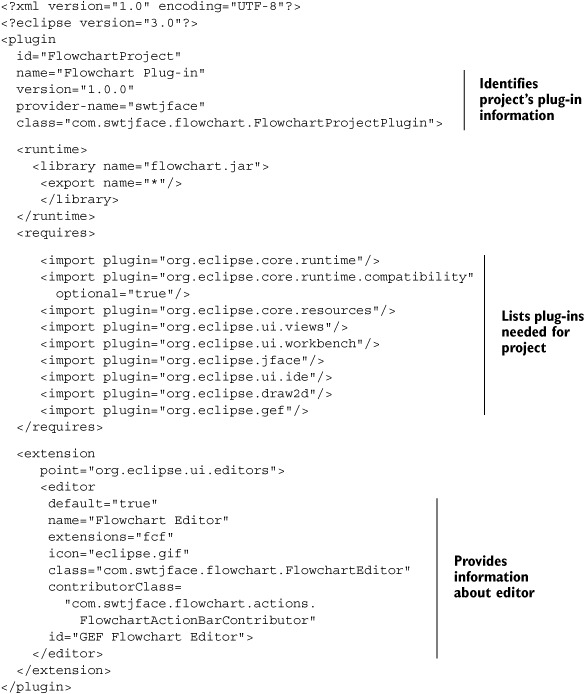
Every Eclipse plug-in describes its characteristics and resource requirements in its plugin.xml file. You can modify this file with Eclipse’s Plug-in Manifest Editor or code it directly. The plugin.xml code for our flowchart editor is shown in listing D.1.
Listing D.1. The plugin.xml file
Note
Since every editor requires an icon, we’ve chosen to use the eclipse32.gif image from org.eclipse.platform_x.y.z. This file must be added to the project in order for the plug-in to function.
The first sections of this file specify the identification information about the plug-in and the libraries it needs to operate. The plug-in class, FlowchartProjectPlugin, has already been created and added to the com.swtjface.flowchart package; this file shouldn’t be modified.
The important configuration information for our editor is contained in the <extension></extension> tags, including the main class for the editor and the contribution class needed to incorporate Workbench Actions into our editor. The line extensions="fcf" ensures that the editor will be activated whenever the user creates a file with the fcf suffix.
Along with the extension for the editor, many GEF projects incorporate a wizard to build an initial *.fcf file for the editor. Doing so is straightforward but beyond the scope of this appendix. For further information about plug-ins, wizard extensions, and XML configuration, we recommend Eclipse in Action, by David Gallardo, Ed Burnette, and Robert McGovern (Manning, 2003).
D.2.2. Adding class libraries
Depending on which version of Eclipse you use, the necessary plug-ins may have already been added to the project. If you open the Plug-in Dependencies in the Package Explorer, you may already see a list of jar files; if so, you can skip this subsection. If not, you need to include a number of class libraries. Since the boot.jar and runtime.jar files were automatically added during project creation, add the JFACE_LIB and WORKBENCH_LIB variables created in appendix A and the DRAW2D_LIB variable created in appendix C. You also need to add the OSGI_LIB variable created in chapter 4.
Unlike the other graphical applications in this book, GEF editors need to be integrated in the Eclipse Workbench. This means you need to add even more libraries. Table D.2 lists the jar files required to work with Workbench parts and recommended names for their classpath variables.
Table D.2. Additional libraries needed for GEF applications
|
Classpath variable |
Library file |
|---|---|
| GEF_LIB | $ECLIPSE/plugins/org.eclipse.gef_x.y.z/gef.jar |
| UI_EDITORS_LIB | $ECLIPSE/plugins/org.eclipse.ui.editors_x.y.z/editors.jar |
| UI_IDE_LIB | $ECLIPSE/plugins/org.eclipse.ui.ide_x.y.z/ide.jar |
| UI_LIB | $ECLIPSE/plugins/org.eclipse.ui_x.y.z/ui.jar |
| UI_VIEWS_LIB | $ECLIPSE/plugins/org.eclipse.ui.views_x.y.z/views.jar |
Once we’ve created these classpath variables and added them to FlowchartProject, we can begin adding packages and classes.
D.2.3. Adding packages and classes
GEF projects keep their code organized with a series of packages that represent different aspects of the editor. Package names may differ from one application to the next, but table D.3 lists those used in the flowchart editor. We recommend that you add them to the FlowchartProject inside the src directory.
Table D.3. Class packages in the flowchart editor
|
Function |
|
|---|---|
| com.swtjface.flowchart | Editor’s EditorPart and plug-in |
| com.swtjface.flowchart.actions | Classes that create and manage Actions |
| com.swtjface.flowchart.commands | Classes used to modify the Model properties |
| com.swtjface.flowchart.dnd | Classes that provide the drag-and-drop capability |
| com.swtjface.flowchart.editpart | Editor’s EditParts |
| com.swtjface.flowchart.figures | Graphics used to create EditPart visuals |
| com.swtjface.flowchart.model | Information contained in the EditParts |
| com.swtjface.flowchart.palette | GUI element used to instantiate EditParts |
| com.swtjface.flowchart.policies | Policies available for the EditParts |
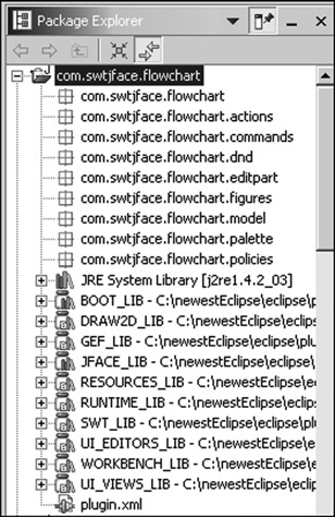
Since the Figure objects for this project have already been written, we can add them to the project. To do this, we move ActivityFigure.java, ChartFigure.java, DecisionFigure.java, FigureFactory.java, FixedAnchor .java, PathFigure.java, ProcessFigure.java, and TerminatorFigure.java to the com.swtjface.flowchart.figures package. The end result of this process is shown in figure D.6.
Figure D.6. The package structure for FlowchartProject
Now that we’ve added these files, we’ve completed the View aspect of the editor. However, these Figures aren’t much use unless users can add them to the editor. Toward this end, our next goal is to discuss GEF palettes.
D.3. Creating the editor’s PaletteViewer
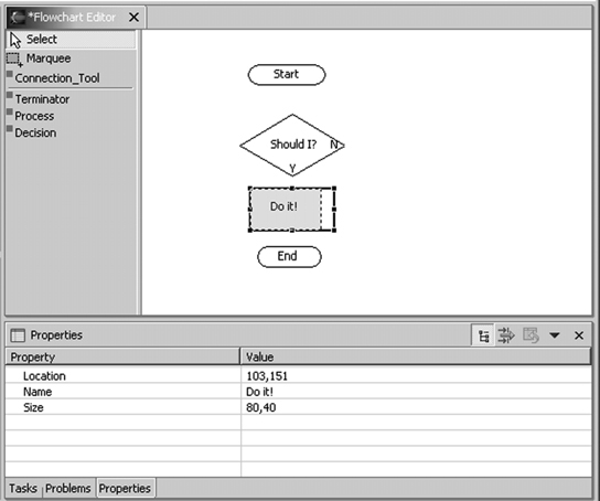
Look at figure D.7. In the simplest terms, it shows a Canvas with a LightweightSystem object—just like any Draw2D application. What differentiates a GEF editor from a Draw2D application or text editor is its Viewer. Viewer classes, as described earlier, rest on top of a component and control its appearance and event handling. In this case, we have two of them: a Viewer that represents the main editor and one that contains the palette. Since the palette is the first object a user will come in contact with, we’ll start our GEF discussion by examining the PaletteViewer.
Figure D.7. The flowchart editor in its dazzling glory
The PaletteViewer class builds components and handles events for the left-hand section of the Canvas, whose default width is 125 pixels. Like the viewer on the right-hand side, it implements the GraphicalViewer interface. But PaletteViewer has a number of distinguishing features:
- The ability to add buttons that provide editing functions, called ToolEntrys
- The ability to add buttons that create new components, called TemplateEntrys
- Configuration information contained in a single object, the PaletteRoot
This PaletteRoot is important for a PaletteViewer because it provides the entries that will be available to the user. Like a Model class, it contains the palette’s information. The getPaletteRoot() method configures one of these objects by creating and populating a List of PaletteGroups. In FlowchartPalette, the first PaletteGroup, toolGroup, contains a List of tool-related entries. The second, templateGroup, contains a List of template-related entries. The code is shown in listing D.2, and we recommend that you add this to the com.swtjface.flowchart.palette package.
Listing D.2. FlowchartPalette.java
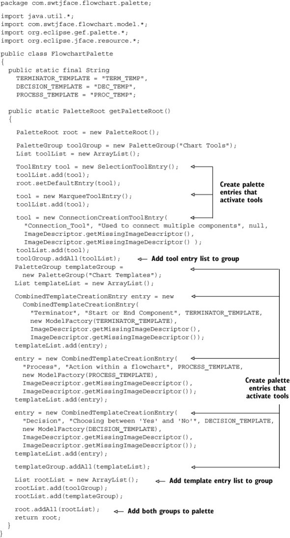
As you can see, a PaletteRoot is a collection of PaletteGroups, which are collections of entries. These entries, represented by the ToolEntry and CombinedTemplateCreationEntry classes, create buttons that will be added to the palette. Except for the SelectionTool and the MarqueeSelectionTool, these entries are initialized with descriptors, images, and classes that implement the CreationFactory interface. But before we can discuss their constructor methods, we need to explain how Tools and templates work.
D.3.1. Handling events with the ToolEntry and Tool classes
The first three entries in our palette are ToolEntrys, which provide the ability to select and connect existing components. Whenever any of these entries are clicked, they create a new Tool object. The top tool entry, labeled Select, creates a SelectionTool; the Marquee entry creates a MarqueeSelectionTool; and the Connection_Tool entry creates a ConnectionCreationTool.
The entries are simple to understand, but what exactly is a Tool? A Tool provides a distinctive means of interpreting keyboard and mouse events. For example, when you click a component with the SelectionTool activated, there will be a different result than if the ConnectionCreationTool had been activated. This is because the two Tools have different handlers for MouseEvents; they also interact differently with components and their EditParts. These Tool/EditPart interactions are accomplished through Requests.
Table D.4 lists a group of important Tools provided in GEF, their functions, and the Requests they send to EditParts during activation.
Table D.4. Class packages in the FlowchartProject project
|
Tool |
Tool description |
Requests |
|---|---|---|
| ConnectionBendpoint Tracker | Creates or moves Bendpoints within a Connection | BendpointRequest |
| ConnectionCreationTool | Tells the EditPart that it will be the start of a new connection | ConnectionCreation Request |
| CreationTool | Creates new EditParts (components) | CreateRequest |
| MarqueeSelectionTool | Selects all the EditParts within the marquee | SelectionRequest |
| ResizeTracker | Tells the EditPart to change its size | ChangeBounds Request |
| SelectionTool | Tells an EditPart that it has been selected or that the mouse cursor has come in contact with the component | SelectionRequest LocationRequest |
It’s important to note that DragTrackers such as ResizeTracker and ConnectionBendpointTracker are also GEF Tools. They determine how DragEvents affect an EditPart. Whereas a Tool’s activation is independent of the components in the editor, DragTrackers are specified in EditParts. In many cases, a high-level Tool transfers its event-handling authority to the DragTracker associated with the EditPart.
For example, when a user clicks a Decision component, the SelectionTool will activate. But if the user presses the button and moves the mouse, then the SelectionTool delegates authority to the DecisionPart’s DragTracker.
Requests
Requests are the means by which Tools perform editing. When a component is clicked with the SelectionTool activated, the Tool sends a SelectionRequest or a LocationRequest to the EditPart. Similarly, when the ConnectionCreationTool is activated, the tool sends a CreateConnectionRequest. In each case, the Request provides the EditPart with information about the event, such as which key was pressed or which button was clicked.
When an EditPart receives a Request, it responds with a Command object if one is available. This Command tells the Tool how the EditPart should be altered when the event occurs. Once the Tool receives a Command, it takes responsibility for modifying the EditPart by invoking the Command’s execute() method. We’ll discuss Commands in depth shortly.
We need to mention two points about Requests. First, there is no subpackage (such as com.swtjface.flowchart.requests) for Requests because GEF already provides all the classes that will be needed in most editors. However, users can create their own Tools and Requests as needed.
Second, although Requests are generally categorized according to their class, they’re further distinguished by a TYPE field. This integer makes the Request’s function more specific. For example, when the mouse hovers over an EditPart, the SelectionTool sends a LocationRequest to the component. Because this LocationRequest’s TYPE field is REQ_SELECTION_HOVER, the part knows that the mouse is hovering above it.
EditDomains and Tools
Although EditDomain objects operate behind the scenes, it’s important to know what they are and how they relate to palettes and palette entries. EditDomains keep track of an editor’s state information, and part of this information consists of which Tool is currently active. The EditDomain sets the editor’s default Tool, which is usually the SelectionTool, and manages the process of switching from one Tool to the next. It ensures that only one Tool is active at any time and directs events to it.
This object also plays a role in creating an editor’s palette. The EditDomain ensures that the PaletteViewer receives the PaletteRoot containing the List of ToolEntrys and TemplateEntrys. Then, it determines which Tool in the List is the default tool and activates this Tool when the editor initializes.
D.3.2. Creating components with templates
At the time of this writing, the GEF documentation describes many classes that create and handle templates, but it never explains exactly what a template is. An examination of the code tells us that a template is any object that can be matched to a component. If you’d like to number your components, then you can use ints or chars as your templates. For our editor, we’ll use Strings. That is, TERM_TEMP is the template that corresponds to the Terminator component, PROC_TEMP represents the Process, and DEC_TEMP represents the Decision.
TemplateEntry objects
Just as a ToolEntry creates Tool objects, TemplateEntrys create templates. After clicking a TemplateEntry in the palette, the user can either drag the template to the editor or click an area in the editor. Once the drop location is determined, the editor’s TemplateTransferDropTargetListener determines how the component will be created.
In our example, the entry list consists of CombinedTemplateCreationEntrys, which create both a template and a CreationEntryTool to create the template’s matching component. The constructor for these entries requires a number of fields to specify its appearance and operation:
- label (a String)— The entry’s name
- shortDesc (a String)— Description when the mouse hovers over the entry
- template (an Object; a String, in our case)— The component to be created
- factory (a CreationFactory)— The class that builds the component
- iconSmall (an ImageDescriptor)— The image shown near the label
- iconLarge (an ImageDescriptor)— The image shown during the drag
For our flowchart editor, we’ll use getMissingImageDescriptor() to provide the icons. These are the small, red squares provided by the JFace library.
So far, we’ve discussed every aspect of palette entry constructors except the CreationFactory.
Converting templates to Model classes with a CreationFactory
Components are created when the user drags a template from the palette and drops it in a container. The CreationTool tells the editor which component to build by identifying a class that implements the CreationFactory interface.
This important interface contains only two methods: getNewObject() receives a template object and returns a newly created Model object for the requested component, and getObjectType() returns the template created by the palette tool. The code in listing D.3 shows how these methods are used in the flowchart editor’s ModelFactory class. We recommend that you place this class in the com.swtjface.flowchart.model package.
Listing D.3. ModelFactory.java

In this case, getNewObject() checks to see if it recognizes the template. If it does, then the method returns a constructed Model object that contains the component’s information. In addition, this class contains two methods, getChart() and getPath(), which return Model objects for the Chart and Path components. These objects require separate methods because they aren’t directly created with templates.
TemplateTransferDropTargetListeners
Like any drag-and-drop operation, a DropTargetListener must be present in order to respond to a DropTargetEvent. GEF provides a class specifically for responding to template drops: TemplateTransferDropTargetListener. This class must be extended to identify the CreationFactory that will construct the Model.
For our flowchart editor, this subclass is FlowchartDropTargetListener; its code is presented in listing D.4. We recommend that you add this class to the com.swtjface.flowchart.dnd package.
Listing D.4. FlowchartDropTargetListener.java
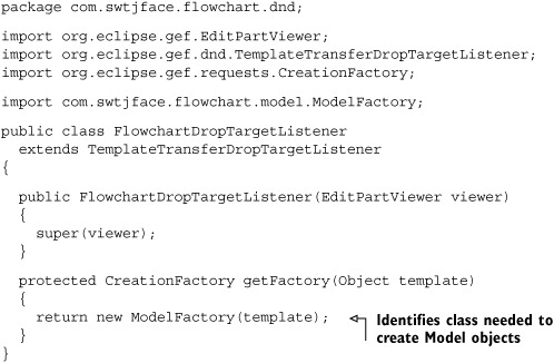
As you can see, the only difference between the FlowchartDropTargetListener and the TemplateTransferDropTargetListener is the ModelFactory class. Now that you know how these Model objects are created, you need to learn how they work.
D.4. The Model aspect: Model classes
The fundamental question in building Model classes is this: What information should be saved to a file? You don’t need to persist each pixel in the main window. A good rule of thumb is that every editable aspect of a component should be saved and incorporated in its Model class. This section will show how these classes are formed and how their structures are used in the flowchart editor.
D.4.1. Model classes and JavaBeans
The role of a Model class is to keep track of a component’s editable characteristics, called properties. Each property has a mutator method (setXYZ()) to specify its value and an accessor method (getXYZ()) to acquire it. The Model class also fires events when these properties change. Both the event and listener classes needed for this are provided by the java.beans package.
This relationship between Model classes and the JavaBean library is deliberate. For those unfamiliar with component-based (JavaBean) software development, the goal is to construct applications with simple, reusable objects that keep track of information. Java doesn’t provide a specific class for JavaBeans, but instead gives rules for their interfaces and methods. Because GEF Model classes follow these rules, they’re considered JavaBeans.
In addition to the accessor and mutator methods, Sun’s JavaBean specification also describes the event model needed for dealing with PropertyChangeEvents. The GEF implementation of this model is shown in figure D.8. It’s important to note that although the methods are contained in the Model class, the EditPart invokes them.
Figure D.8. The PropertyChangeEvent model for GEF Model classes
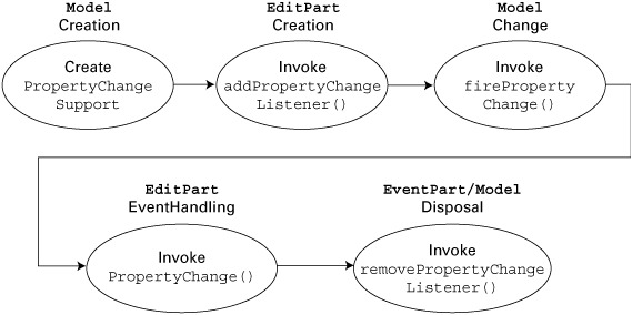
First, a Model object creates a PropertyChangeSupport instance during its creation. This enables an EditPart to listen to its PropertyChangeEvents. Then, when the EditPart is created, it calls the Model’s addPropertyChangeListener() method to be able to respond to these events. Whenever a property changes, the Model calls its firePropertyChange() method, and the EditPart handles the Event with its propertyChange() method. When the component is deallocated, the EditPart calls the Model’s removePropertyChangeListener() method.
These methods must be available in each Model class you build. Therefore, you can save yourself effort by creating an abstract class for your Models.
D.4.2. The AbstractChartElement class
Since all Model classes must contain these event-handling methods, it makes sense to incorporate them in an abstract class. For our project, this class is called AbstractChartElement. Listing D.5 presents the code for this class; we recommend that you add it to the com.swtjface.flowchart.model package.
Note
This class provides listeners for receiving events and methods to fire them, but it doesn’t implement propertyChange(PropertyChangeEvent), which is the only event-handling method in the PropertyChangeListener interface. This method is invoked by the EditPart, which controls the Model and View.
Listing D.5. AbstractChartElement.java

Each of the property changes has a String as a label. The first three, SIZE, LOC, and NAME, refer to changes in a component’s size, location, and message, respectively. A CHILD property change is fired whenever a new part is added to the container (Chart). Similarly, TARGETS and SOURCES events are fired whenever a new source or target connection is made or removed.
Another important point about this class is that it implements the Serializable interface. This means concrete subclasses can be converted into bytes and persisted in a file. The transient keyword preceding the PropertyChangeSupport declaration means that this class cannot be serialized. Therefore, when the top-level Model is saved to a file, it won’t include these objects. For this reason, the readObject() method at the end of the code creates a new PropertyChangeSupport object when the Model is deserialized.
By making our Model classes descendants of AbstractChartElement, we ensure that each of these methods will be available. The first concrete Model class that we’ll discuss is Chart, which holds the information concerning the editor’s container.
D.4.3. The Chart class
Despite its importance, a Chart object doesn’t hold a great deal of data. Its function is to keep track of child Model classes by adding and removing them from an ArrayList. The code for this class is shown in listing D.6; add it to com.swtjface.flowchart.model.
Listing D.6. Chart.java
package com.swtjface.flowchart.model;

import java.util.*;

public class Chart
  extends AbstractChartElement
{
  protected List children = new ArrayList();

  public List getChildren()
  {
    return children;
  }

  public void addChild(Activity child)
  {
    children.add(child);
    firePropertyChange(CHILD, null, child);
  }

  public void removeChild(Activity child)
  {
    children.remove(child);
    firePropertyChange(CHILD, null, child);
  }
}
These methods are straightforward: addChild() and removeChild() perform the essential job of mutator methods, whereas getChildren() provides access to the object’s properties. If any properties change, then a PropertyChangeEvent is created and fired.
The Chart class may not be exciting, but as you’ll see later, it’s vital in saving the editor’s contents to a file. Now that you’ve seen how these children are arranged, let’s look at their abstract superclass, Activity.
D.4.4. The Activity class
For the flowchart editor’s Decision, Process, and Terminator components, five fields need to be stored:
- size— The part’s x and y dimensions, represented by a Dimension
- location— The part’s position, represented by a Point
- name— The part’s message, represented by a String
- sources— The part’s SourceConnections, contained in a Vector
- targets— The part’s TargetConnections, contained in a Vector
Since this list is the same for each Model, we’ll use the same class, Activity, to hold the information for the components. This class will contain mutator and accessor methods for each of the above properties.
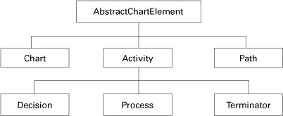
Now that we have the Activity class, we can see the entire Model class hierarchy, shown in figure D.9.
Figure D.9. The Model classes of the flowchart editor
The full code for the Activity class is shown in listing D.7.
Listing D.7. Activity.java
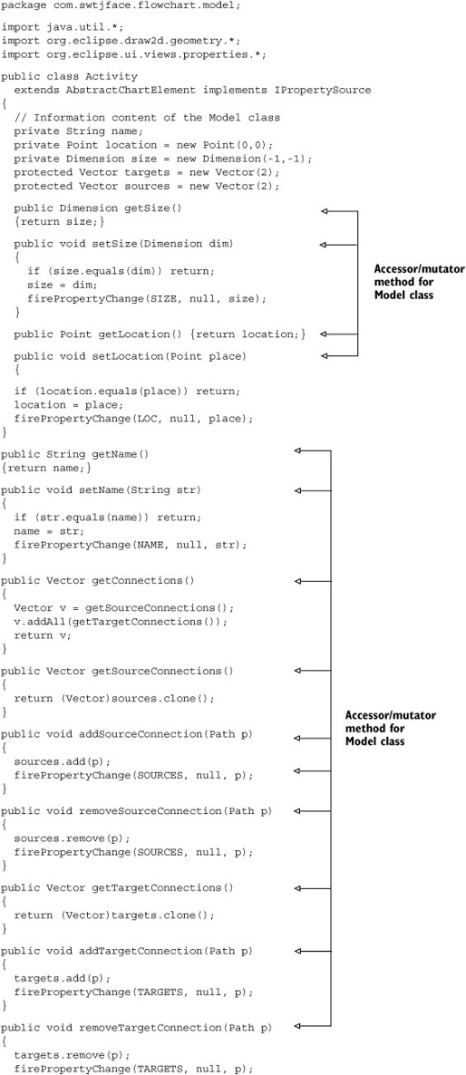

A bit longer than the Chart Model, isn’t it? As you can see, keeping track of many properties can be complicated, especially Connections. But in addition, we’ve added six methods needed to implement the IPropertySource interface. By doing so, users can change the size, location, and name of an Activity component using a Property View. This window is provided by the Eclipse Workbench; an example is shown in figure D.10.
Figure D.10. Example property view for the flowchart editor
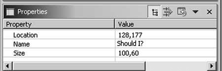
The IPropertySource methods make it possible to transfer property values between the Model and Eclipse’s Property View: The first method, getPropertyDescriptors(), tells the View what properties it needs to display and that input should be provided through a textbox. The next two methods get and set the EditPart’s property values; the fourth, resetPropertyValue(), returns the default property. isPropertySet() returns whether the property value is equal to its default, and getEditableValue() returns the object responsible for keeping track of the EditPart’s property.
Now that we’ve taken care of the abstract superclass, we need to create the concrete subclasses. The code for these Model classes—Decision, Process, and Terminator—is shown in listings D.8, D.9, and D.10.
Listing D.8. Decision.java
package com.swtjface.flowchart.model;

import org.eclipse.draw2d.geometry.Dimension;

public class Decision extends Activity
{
  public Decision()
  {
    setName("Decision");
    setSize(new Dimension(100,60));
  }
}
Listing D.9. Process.java
import org.eclipse.draw2d.geometry.Dimension;

public class Process extends Activity
{
  public Process()
  {
    setName("Process");
    setSize(new Dimension(80,40));
  }
}
Listing D.10. Terminator.java
package com.swtjface.flowchart.model;

import org.eclipse.draw2d.geometry.Dimension;

public class Terminator extends Activity
{
  public Terminator()
  {
    setName("Term");
    setSize(new Dimension(80,20));
  }
}
These classes do nothing more than set their message and size during construction. It’s easy to remove them and use only the Activity Model class. However, for the purposes of teaching the GEF, we’ve made sure that each MVC triple has its own Model class.
D.4.5. The Path class
In addition to creating classes for the Activity components, we need to create Model classes for their Connections. This Path class doesn’t fire PropertyChangeEvents or display information in the Property View, but it keeps track of which Activity objects it connects (source and target) and the names of its anchors (sourceName and targetName). The code for this class is provided in listing D.11.
Listing D.11. Path.java
package com.swtjface.flowchart.model;

public class Path
  extends AbstractChartElement
{
  protected Activity source, target;
  protected String sourceName, targetName;

  public void attachSource()
  {
    if (getSource() == null ||
      getSource().getSourceConnections().contains(this))
      return;
    getSource().addSourceConnection(this);
  }

  public void detachSource()
  {
    if (getSource() == null)
      return;
    getSource().removeSourceConnection(this);
  }

  public void attachTarget()
  {
    if (getTarget() == null ||
      getTarget().getTargetConnections().contains(this))
      return;
    getTarget().addTargetConnection(this);
  }

  public void detachTarget()
  {
    if (getTarget() == null)
      return;
    getTarget().removeTargetConnection(this);
  }

  public Activity getSource()
  {
    return source;
  }

  public void setSource(Activity e)
  {
      source = e;
  }

  public Activity getTarget()
  {
    return target;
  }

  public void setTarget(Activity e)
  {
    target = e;
  }

  public String getSourceName()
  {
    return sourceName;
  }

  public void setSourceName(String s)
  {
    sourceName = s;
  }

  public String getTargetName()
  {
    return targetName;
  }

  public void setTargetName(String s)
  {
    targetName = s;
  }
}
Again, these methods are easy to understand. The only new concepts involve attaching and detaching Connections. These functions tell their source and target Activity Models that a new Connection has been added or removed. This is one of the few instances where one Model class interacts with another.
The process of modifying components begins with the mutator methods of the Model classes and the PropertyChangeEvents that they fire. However, these methods are only invoked by Command objects. Therefore, to continue discussing the editing process, our next step must involve investigating Commands.
D.5. Changing Model properties with Commands
When we briefly discussed Commands in the last section, we mentioned how they’re created in response to Requests. We can’t discuss the full process by which a Request becomes a Command just yet. But in this section, we’ll describe the Command’s purpose and structure and then build customized classes for our editor.
D.5.1. Commands and CommandStacks
It’s possible to extend the Request class, but doing so is generally unnecessary since GEF provides so many subclasses of its own. However, you’ll have to build all your own Command classes; you must do so because Commands interact with Model objects, which have no standard structure beyond accessor/mutator methods. But GEF does provide an abstract Command class, and it’s important that you understand how it works.
The execute() method performs the real work of the Command by invoking the mutator methods (setXYZ()) of the Model class. This execute() method is called by the active Tool after it receives the Command in response to its Request. Commands can also have other methods and fields associated with them, and these are generally used to provide information for the execute() method.
Two other important Command methods are undo() and redo(). As expected, these methods are used to reverse the results of execute() or reinvoke it. For these methods to work, the editor must keep track of which Commands have been executed. The data structure used for this task is the CommandStack, which is initialized during the editor’s construction. This object pushes executed Commands onto its Undo stack and pushes undone Commands onto its Redo stack. The Redo stack is cleared whenever a new Command is executed.
Our flowchart editor needs four concrete Command classes. We’ll start with the first Command that will be executed in a normal GEF editor: the CreateCommand.
D.5.2. The CreateCommand class
The CreateCommand is used to update the Chart container with a new component. It also initializes the properties of the new component by setting its size and location. The execute() method of the CreateCommand is simple and requires only the Model class of the parent (parent), the added child (child), and the child’s bounds (rect). The code is provided in listing D.12.
Listing D.12. CreateCommand.java
package com.swtjface.flowchart.commands;

import org.eclipse.draw2d.geometry.Rectangle;
import org.eclipse.gef.commands.Command;
import com.swtjface.flowchart.model.*;

public class CreateCommand extends Command
{
  private Chart parent;
  private Activity child;
  private Rectangle rect;

  public void execute()
  {
    if (rect != null)
    {
      child.setLocation(rect.getLocation());
      if (!rect.isEmpty())
        child.setSize(rect.getSize());
     }
    parent.addChild(child);
  }

  public void setParent(Chart sa)
  {parent = sa;}

  public void setChild(Activity activity)
  {child = activity;}

  public void setConstraint(Rectangle bounds)
  {rect = bounds;}

  public void redo()
  {execute();}

  public void undo()
  {parent.removeChild(child);}
}
The execute() method calls the setLocation() and setSize() methods of the Activity object and adds the new child to the Chart with its addChild() method. The redo() method reinvokes execute(), and undo() calls the removeChild() method. The setParent(), setChild(), and setConstraint() methods provide initialization parameters to the Command during its formation.
The CreateCommand class is simple to understand. However, because the PathCommand deals with Path objects, it’s slightly more complicated.
D.5.3. The PathCommand class
The process of creating a Connection presents greater complications than building a child Model class in a parent. With connections, or Paths in our case, the Model must keep track of both of the components to which it’s attached and the names of the anchors in each component. Also, just as the CreateCommand adds an Activity to a Chart, this command tells both the source and target Activity objects to add this Path to their ArrayLists (see listing D.13).
Listing D.13. PathCommand.java
package com.swtjface.flowchart.commands;

import org.eclipse.gef.commands.Command;
import com.swtjface.flowchart.model.*;

public class PathCommand
      extends Command
{
  protected Activity oldSource, source;
  protected Activity oldTarget, target;
  protected String oldSourceName, sourceName;
  protected String oldTargetName, targetName;
  protected Path path;

  public PathCommand()
  {}

  public boolean canExecute()
  {
    return true;
  }

  public void execute()
  {
    if (source != null)
    {
      path.detachSource();
      path.setSource(source);
      path.setSourceName(sourceName);
      path.attachSource();
    }
    if (target != null)
    {
      path.detachTarget();
      path.setTarget(target);
      path.setTargetName(targetName);
      path.attachTarget();
    }
  }

  public void redo()
  {
    execute();
  }

  public void undo()
  {
    source = path.getSource();
    target = path.getTarget();
    sourceName = path.getSourceName();
    targetName = path.getTargetName();

    path.detachSource();
    path.detachTarget();
    path.setSource(oldSource);
    path.setTarget(oldTarget);
    path.setSourceName(oldSourceName);
    path.setTargetName(oldTargetName);

    path.attachSource();
    path.attachTarget();
  }

  public void setSource(Activity newSource)
  {
    source = newSource;
  }

  public void setSourceName(String newSourceName)
  {
    sourceName = newSourceName;
  }

  public void setTarget(Activity newTarget)
  {
    target = newTarget;
  }

  public void setTargetName(String newTargetName)
  {
    targetName = newTargetName;
  }

  public void setPath(Path p)
  {
    path = p;
    oldSource = p.getSource();
    oldTarget = p.getTarget();
    oldSourceName = p.getSourceName();
    oldTargetName = p.getTargetName();
  }
}
This Command changes the properties of the Path and its source and target Activity objects, but not the Chart. It’s important to understand that Connection objects aren’t considered children of other components; they’re part of an internal Vector in each EditPart.
Now that you know how new Model classes are created, the next class describes how they’re removed from the Chart and deallocated.
D.5.4. The DeleteCommand class
The DeleteCommand reverses the actions of both the CreateCommand and the PathCommand and is performed in two steps. First, it deletes the Path objects associated with the selected component. This process involves detaching the Path from both the deleted component and the one to which it was attached. The second step removes the child Activity from the parent Chart. This is shown in listing D.14.
Listing D.14. DeleteCommand.java
package com.swtjface.flowchart.commands;

import java.util.*;

import org.eclipse.gef.commands.Command;
import com.swtjface.flowchart.model.*;

public class DeleteCommand extends Command
{
  private Chart parent;
  private Activity child;
  private List sourceConnections = new ArrayList();
  private List targetConnections = new ArrayList();

  private void deleteConnections(AbstractChartElement a)
  {
    if (a instanceof Chart)
    {
      List children = ((Chart)a).getChildren();
      for (int i = 0; i < children.size(); i++)
        deleteConnections((Activity)children.get(i));
      }
    else
    {
      sourceConnections.addAll
        (((Activity)a).getSourceConnections());
      for (int i = 0; i < sourceConnections.size(); i++)
      {
        Path path = (Path)sourceConnections.get(i);
        path.detachSource();
        path.detachTarget();
      }
      targetConnections.addAll
        (((Activity)a).getTargetConnections());
      for (int i = 0; i < targetConnections.size(); i++)
      {
        Path path = (Path)targetConnections.get(i);
        path.detachSource();
        path.detachTarget();
      }
    }
  }

  public void execute()
  {
    deleteConnections(child);
     parent.removeChild(child);
  }

  private void restoreConnections()
  {
    for (int i = 0; i < sourceConnections.size(); i++)
    {
      Path path = (Path)sourceConnections.get(i);
      path.getTarget().addTargetConnection(path);
      path.getSource().addSourceConnection(path);
    }
    sourceConnections.clear();
    for (int i = 0; i < targetConnections.size(); i++)
    {
      Path path = (Path)targetConnections.get(i);
      path.getSource().addSourceConnection(path);
      path.getTarget().addTargetConnection(path);
    }
    targetConnections.clear();
  }

  public void setChild (Activity a)
  {child = a;}

  public void setParent(Chart c)
  {parent = c;}

  public void redo()
  {execute();}

  public void undo()
  {
    parent.addChild(child);
    restoreConnections();
  }
}
The code is somewhat involved, but the theory of operation is straightforward. The execute() method removes the Path objects from both the source and target Activity objects, and then it removes the deleted Activity objects from the Chart. The undo() method restores the component’s connections and adds it to the Chart.
D.5.5. The SetConstraintCommand class
So far, we’ve created Commands that modify every aspect of the editor’s Model except the appearance of the individual components. Since we want the user to be able to change the size and shape of Activity objects, we need to create a Command that invokes their appropriate mutator methods. This is the purpose of the SetConstraintCommand, which is one of the simplest of the Commands in our project. Its code is presented in listing D.15.
Listing D.15. SetConstraintCommand.java
package com.swtjface.flowchart.commands;

import org.eclipse.draw2d.geometry.*;
import com.swtjface.flowchart.model.*;

public class SetConstraintCommand
  extends org.eclipse.gef.commands.Command
{

  private Point oldPos, newPos;
  private Dimension oldSize, newSize;
  private Activity act;

  public void execute()
  {
    oldSize = act.getSize();
    oldPos  = act.getLocation();
    act.setLocation(newPos);
    act.setSize(newSize);
  }

  public void setLocation(Rectangle r)
  {
    setLocation(r.getLocation());
    setSize(r.getSize());
  }

  public void setLocation(Point p)
  {newPos = p;}

  public void setPart(Activity part)
  {this.act = part;}

  public void setSize(Dimension p)
  {newSize = p;}

  public void redo()
  {
    act.setSize(newSize);
      act.setLocation(newPos);
  }

  public void undo()
  {
    act.setSize(oldSize);
    act.setLocation(oldPos);
  }
}
This Command changes the Activity’s size and location parameters, but not its name. For this, we’ll use a direct statement from the Activity’s EditPart, which we’ll discuss next.
D.6. The Controller aspect: EditPart classes
Now that we’ve handled the View and Model aspects of the application’s components, we need to start building their Controllers, represented by EditPart objects. Previously, we described the function of a Controller as “everything else,” but now we need to be more specific. An EditPart’s activity may be divided into three main functions:
- Respond to Model changes and update the component’s View
- Keep track of the component’s Connections and ConnectionAnchors
- Activate EditPolicys and associate them with their editing roles
The first function is important to understand. An EditPart’s activate() method is called during its creation. This invokes the Model’s addPropertyChangeListener() method and enables the EditPart to respond to property changes in the Model. This response is performed with the propertyChange() method, which updates the View with the new information from the Model.
For example, when a SetConstraintCommand is executed, it calls the Model’s setSize() and setLocation() methods. When these properties change, the two PropertyChangeEvents are received by the EditPart, which modifies the Figure’s size and location.
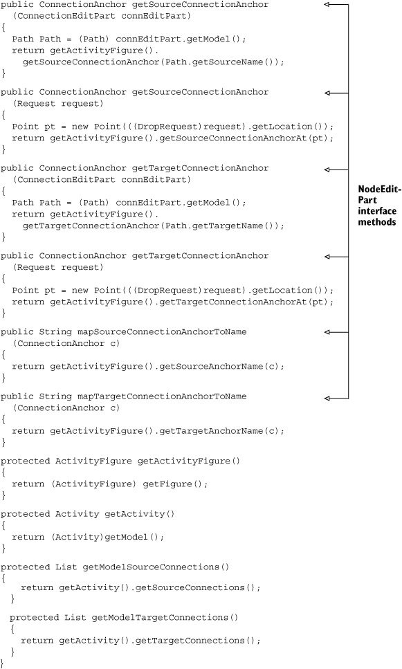
In addition to updating size and location, many EditParts must manage Connection objects. These EditParts need to implement the NodeEditPart interface, which provides methods for matching Connections with ConnectionAnchors. When a PathCommand needs to know where to attach a new Connection, it communicates with a NodeEditPart.
The last EditPart function deals with EditPolicys, which determine the different ways the component can be edited. These policies function by creating Command objects in response to Requests. An EditPart specifies its applicable policies with the createEditPolicies() method and contains them in a List. We’ll discuss these objects further in the next section.
Although we refer to these objects as EditParts, all of the GEF Controllers are really extensions of the AbstractGraphicalEditPart class. This class provides many of the methods needed for Connection management and child/parent interaction. It also creates a default DragTracker object to handle DragEvents. The EditPart class hierarchy for our flowchart editor is shown in figure D.11. Just as we had an abstract class for Activity models, we now have an abstract ActivityPart for our Process, Decision, and Terminator EditParts. The editor also includes ChartParts for the container and PathParts that extend the ConnectionEditPart class.
Figure D.11. The EditPart hierarchy for the flowchart editor

Before we can discuss the individual classes, we need to show how these objects are created. Therefore, our next subject is the EditPartFactory class.
D.6.1. Creating new EditParts with EditPartFactory objects
Earlier, we showed how palettes add Model classes to the parent container, but we didn’t mention how new EditParts are formed. When a new child Model is created from its template, the parent Model fires a PropertyChangeEvent. In response, the parent EditPart invokes its refreshChildren() method. If any child Models exist without matching EditParts, then this method calls the createChild() method.
createChild() accesses the editor’s EditPartFactory object. Just as our ModelFactory created Model classes according to templates, our PartFactory creates EditParts according to their Models. The interface specifies only one method, createEditPart(); as listing D.16 shows, this is the only method we need. If you’re coding these classes, we recommend that you add this class (and all the classes in this section) to the com.swtjface.flowchart.editpart package.
Listing D.16. PartFactory.java
package com.swtjface.flowchart.editpart;

import org.eclipse.gef.EditPart;
import org.eclipse.gef.EditPartFactory;
import com.swtjface.flowchart.model.*;
import com.swtjface.flowchart.model.Process;

public class PartFactory implements EditPartFactory
{
  public EditPart createEditPart(EditPart context, Object model)
  {
    EditPart part = null;
    if (model instanceof Decision)
      part = new DecisionPart();
    else if (model instanceof Process)
      part = new ProcessPart();
    else if (model instanceof Terminator)
      part = new TerminatorPart();
    else if (model instanceof Path)
      part = new PathPart();
    else if (model instanceof Chart)
      part = new ChartPart();
    part.setModel(model);
    return part;
  }
}
Like the ModelFactory class, the PartFactory is simple. However, the operation of the individual EditParts is more involved. We’ll begin with the parent EditPart of the flowchart editor, the ChartPart.
D.6.2. The ChartPart class
A GraphicalViewer object is initialized by specifying the highest-level Model class in the editor. In our case, this is the Chart class. Afterward, it calls its setContents() method, which tells the PartFactory to create a new ChartPart. The viewer’s RootEditPart uses this object to create, activate, and remove child components from the editor. The code for this class is presented in listing D.17.
Listing D.17. ChartPart.java
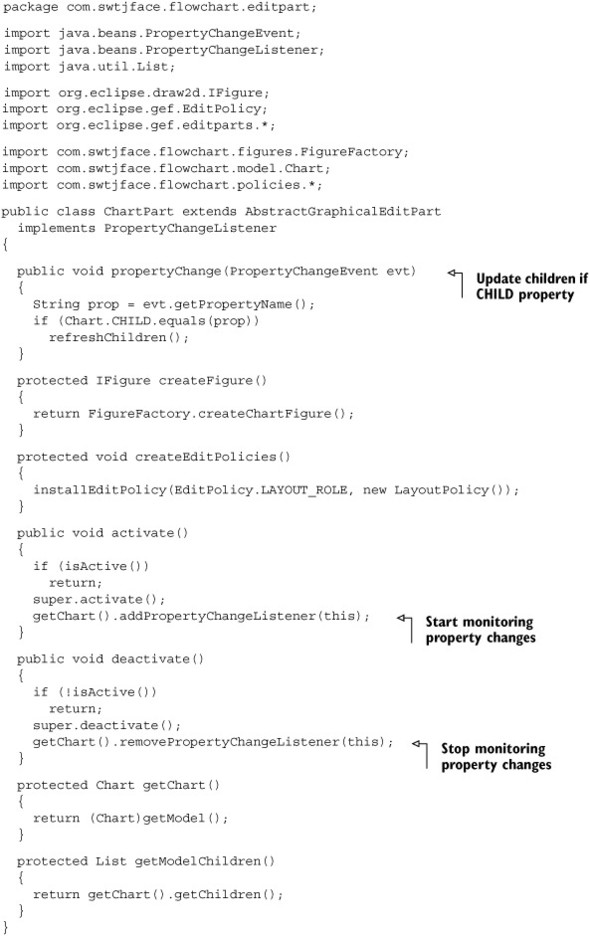
The first method handles the PropertyChangeEvents created by the Chart object. When invoked, it calls refreshChildren(), which activates child EditParts and removes deleted children. The next method, createFigure(), builds a ChartFigure using the FigureFactory. The createEditPolicies() method sets two policies for the part and the roles they will perform. The next two methods take care of activation and deactivation, and the last two methods access the Model object of the EditPart and its children.
D.6.3. The ActivityPart class
Because of its connections and properties, the ActivityPart contains more methods than any other EditPart in our project. But, as shown in listing D.18, the structure remains similar to that of ChartPart.
It begins with the event-handling method, propertyChange(), and continues with the methods needed to alter the View. It contains activate() and deactivate() methods, and it adds EditPolicys to its internal List. But after its Model-accessing methods, the ActivityPart contains four methods related to ConnectionAnchor objects. These are the methods that the class must provide as part of the NodeEditPart interface, which makes the process of adding and removing Connections possible.
Listing D.18. ActivityPart.java
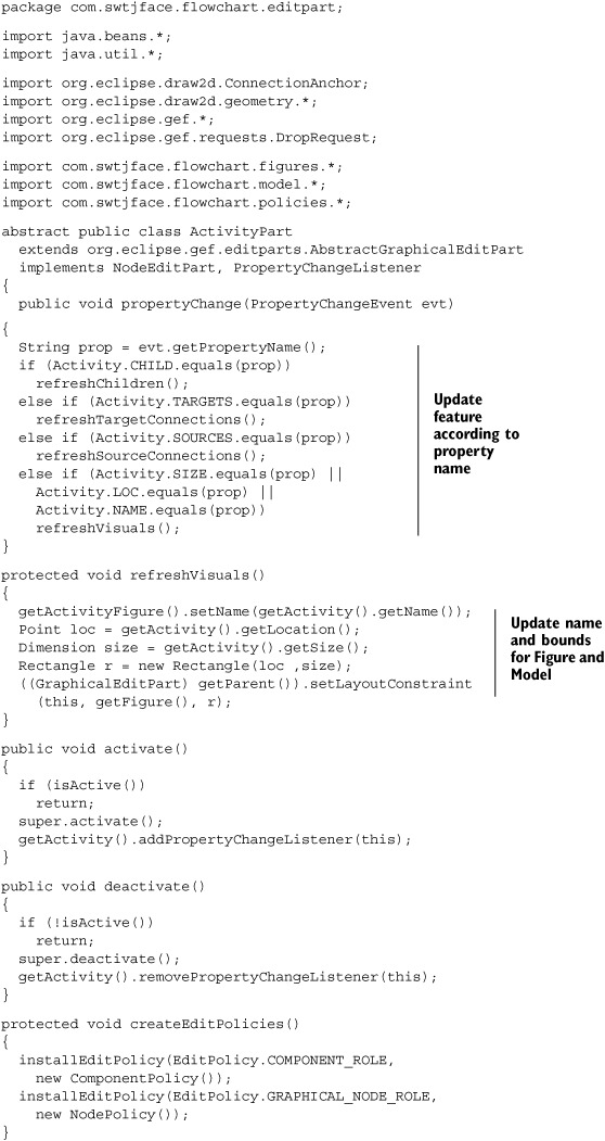
The one method not included in the ActivityPart is createFigure(), which is needed to initialize the component’s View aspect. Because this is the only distinguishing factor between the ActivityPart’s subclasses, it must be specified in the ProcessPart, DecisionPart, and TerminatorPart classes. The code for these classes is shown in listings D.19, D.20, and D.21.
Listing D.19. ProcessPart.java
package com.swtjface.flowchart.editpart;

import org.eclipse.draw2d.IFigure;
import com.swtjface.flowchart.figures.FigureFactory;

public class ProcessPart extends ActivityPart
{
  protected IFigure createFigure()
  {
    return FigureFactory.createProcessFigure();
  }
}
Listing D.20. DecisionPart.java
package com.swtjface.flowchart.editpart;

import org.eclipse.draw2d.IFigure;
import com.swtjface.flowchart.figures.FigureFactory;

public class DecisionPart extends ActivityPart
{
  protected IFigure createFigure()
  {
    return FigureFactory.createDecisionFigure();
  }
}
Listing D.21. TerminatorPart.java
package com.swtjface.flowchart.editpart;

import org.eclipse.draw2d.IFigure;
import com.swtjface.flowchart.figures.FigureFactory;

public class TerminatorPart extends ActivityPart
{
  protected IFigure createFigure()
  {
    return FigureFactory.createTerminatorFigure();
  }
}
It’s important to note that the ActivityPart object responds to events related to new and deleted Connections, but the PathPart doesn’t. This is the case because these events are triggered only once the source and target Connections are added to the Activity’s Model.
D.6.4. The PathPart class
Since the PathPart doesn’t respond to Connection changes, and its activation and deactivation are handled by the ConnectionEditPart superclass, all our class needs to do is specify its applicable policies and the Figure that should be constructed upon its creation. The code is shown in listing D.22.
Listing D.22. PathPart.java
package com.swtjface.flowchart.editpart;

import org.eclipse.draw2d.*;

import org.eclipse.gef.editparts.AbstractConnectionEditPart;
import com.swtjface.flowchart.figures.FigureFactory;

public class PathPart extends AbstractConnectionEditPart
{
  protected void createEditPolicies()
  { }

  protected IFigure createFigure()
  {
    return FigureFactory.createPathFigure();
  }
}
Now that we’ve completed building the EditParts for the flowchart editor, we need to examine their policies. This will enable us to finally show the entire process of how a Tool’s Request becomes a Model’s Command.
D.7. Creating Commands with EditPolicy objects
Let’s say that your editing project has a ChangeColorCommand, and you want this Command to execute whenever the component receives a DirectEditRequest. For another component, you want the ChangeShapeCommand to be executed for this Request. Clearly, you need to modify the EditPart classes of these components, since these are the objects that receive Requests. But how do you make this distinction?
The answer involves EditPolicys, which make it possible for EditParts to control how Commands are created in response to Requests. This section discusses how EditPolicy objects operate, the policies provided by the GEF, and how they’re implemented in our editor.
D.7.1. The getCommand() method
Just as execute() makes Command operation possible, the getCommand() method performs the work for EditPolicys. Once a Tool determines which EditPart should receive a given Request, it calls the part’s getCommand() method with the Request object as its parameter. Then, the EditPart iterates through its list of EditPolicy objects and invokes each of their getCommand() methods. In each case, if the policy can respond to the Request, it returns a Command object to the Tool, which executes it.
In addition, EditPolicys provide information to the Command that specify how its execution should be performed. That is, they tell the Command which Model properties should be modified and provide any parameters associated with the Request.
D.7.2. GEF policies in the flowchart editor
Although you can create customized EditPolicys from scratch, the GEF toolset provides a number of helpful abstract classes. To build concrete EditPolicys, you only need to specify which Model objects and properties should be changed when the Command executes. This section describes the main abstract policies we’ll need for our editor and how you can extend them.
The flowchart editor needs three policies in order to function:
- ComponentPolicy— Removes Activity objects from the Chart
- NodePolicy— Manages the process of adding new Paths
- LayoutPolicy— Creates and arranges Activity objects in the Chart
Each of these classes extends an existing GEF policy class. Their inheritance structure is shown in figure D.12.
Figure D.12. The EditPolicy structure of the flowchart editor. Concrete classes are shown in gray and abstract superclasses in white.

The ComponentEditPolicy creates Commands when an EditPart is deleted or orphaned from a container. The GraphicalEditPolicy contains a number of subclasses for creating, deleting, and adding children to a LayoutManager. The GraphicalNodeEditPolicy subclass creates Commands for creating connections to and from a component. The GEF library provides many more policies than those shown in figure D.12, particularly subclasses of GraphicalEditPolicy; the library’s documentation summarizes their functions.
Although our naming convention may seem lazy, there is a good reason. As we add new components and more functionality to the editor, we need to keep track of component behaviors. If we use names like ChartPolicy and ActivityPolicy, then it will be difficult to see which capabilities are present and which need to be added. Therefore, our policy names closely resemble those of their superclasses.
The LayoutPolicy class
The top-level policy in our project is the LayoutPolicy, which handles creating, deleting, and reshaping components in the ChartPart. This policy places children according to a Rectangle constraint, which specifies the component’s dimensions and size. In addition, it lets the user resize children by creating a ResizableEditPolicy for each of its children.
The code for this class is shown in listing D.23. This, and all classes in this section, should be added to the com.swtjface.flowchart.policies package.
Listing D.23. LayoutPolicy.java
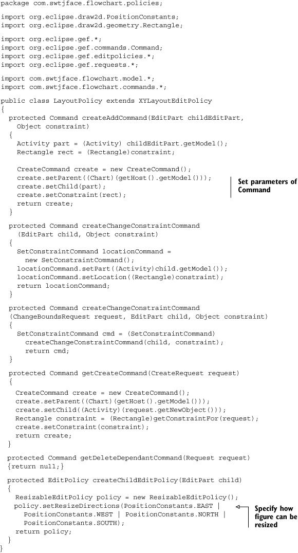
The createAddCommand() and getDeleteDependantCommand() methods return null because their functions are already accomplished: getCreateCommand() takes care of building new components, and getDeleteCommand() deletes them. This second method is part of our next policy, the ComponentPolicy.
The ComponentPolicy class
The ComponentEditPolicy superclass provides Commands when the user wants to remove a component from its container (make it an orphan) or delete it altogether. Since our only container in the flowchart is the ChartPart, there is no difference between becoming an orphan and being deleted. So, the only method in listing D.24 creates a DeleteCommand.
Listing D.24. ComponentPolicy.java
package com.swtjface.flowchart.policies;

import org.eclipse.gef.commands.Command;
import org.eclipse.gef.editpolicies.*;
import org.eclipse.gef.requests.*;

import com.swtjface.flowchart.model.*;
import com.swtjface.flowchart.commands.*;

public class ComponentPolicy extends ComponentEditPolicy
{
  protected Command createDeleteCommand(GroupRequest request)
  {
    Object parent = getHost().getParent().getModel();
    DeleteCommand deleteCmd = new DeleteCommand();
    deleteCmd.setParent((Chart)parent);
    deleteCmd.setChild((Activity)getHost().getModel());
    return deleteCmd;
  }
}
Because our ActivityParts have so much work to do, they require two policies. The ComponentPolicy shown in listing D.24 lets them handle their responsibilities as child components. But in order to manage Connection objects, they need a NodePolicy.
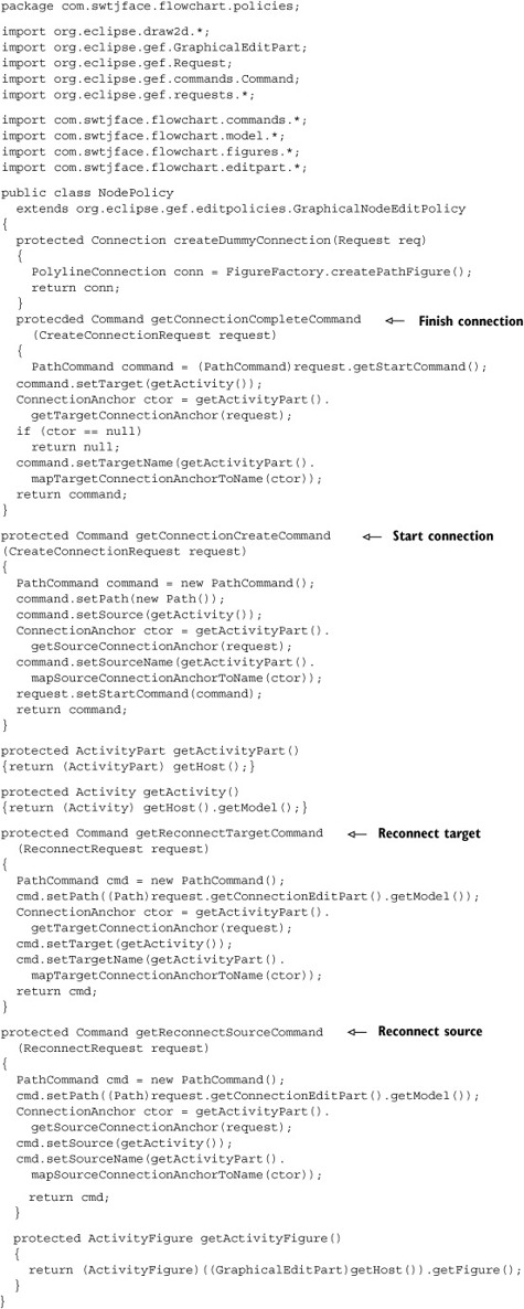
The NodePolicy class
The abstract GraphicalNodeEditPolicy class creates and initializes the parameters of a PathCommand. The subclass in our editor is called NodePolicy, and its code is shown in listing D.25. The createDummyConnection() serves an interesting purpose: It doesn’t create a real Connection, but instead displays a new connection to the user before they choose a target component.
Listing D.25. NodePolicy.java
We’ve presented Tools, Requests, Commands, and EditPolicys. But one class of GEF objects demands our attention: Actions make it possible for menu items and toolbar options to perform the same kind of functionality as Tools, and they’re the subject of the next section.
D.8. Adding Actions to the editor
Users expect multiple ways to accomplish an editing task. For example, the Eclipse Workbench lets users copy GUI elements with a keystroke (Ctrl-C), a menu item (Edit->Copy), or an option in a context menu. GEF enables you to provide these capabilities through Actions.
These are essentially the same JFace Actions as those discussed in Chapter 4. They can be associated with text, images, and accelerator keys; and they can appear as buttons, toolbar items, or options in a menu. However, GEF’s Actions have two important differences.
First, they’re subclasses of WorkbenchPartAction, whose hierarchy is shown in figure D.13. Second, although they invoke run() when activated, their operation varies from class to class. A SelectionAction functions like a Tool by sending the selected component a Request. StackActions function by accessing the CommandStack, and EditorPartActions work by accessing the EditorPart itself.
Figure D.13. A context menu in a GEF editor
In order to function, WorkbenchPartActions need to notify the editor of their presence. This is accomplished by adding them to the editor’s ActionRegistry.
D.8.1. The ActionRegistry and ContextMenus
Every GraphicalEditor creates an ActionRegistry as part of its initialization and populates it by calling createActions(). The code is shown here:
action = new UndoAction(this);
registry.registerAction(action);
getStackActions().add(action.getId());

action = new RedoAction(this);
registry.registerAction(action);
getStackActions().add(action.getId());

action = new SelectAllAction(this);
registry.registerAction(action);

action = new DeleteAction((IWorkbenchPart)this);
registry.registerAction(action);
getSelectionActions().add(action.getId());

action = new SaveAction(this);
registry.registerAction(action);
getPropertyActions().add(action.getId());

action = new PrintAction(this);
registry.registerAction(action);
We mention this code for two reasons. First, it’s helpful to know which Actions have already been added to your GraphicalEditor by default. It also shows that, in addition to the ActionRegistry, the editor keeps track of certain groups of Action classes.
These groups include PropertyActions, which deal with changes to the editor’s state; StackActions, which manipulate the CommandStack; and SelectionActions, which communicate with selected components. If you intend to add custom Actions to your editor, you need to register them in the ActionRegistry and add them to any groups to which they belong. You do so by implementing the createActions() method in your editor.
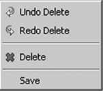
After you add your Actions to the editor, you need to make them available to the user. One of the simpler ways to do this involves a ContextMenu, shown in figure D.14. This menu is easily accessible by right-clicking in the editor’s main window.
Figure D.14. Actions provided by the GEF

For our flowchart editor, we’ll only use the Actions that are added by default, so we won’t need to create any new classes. Instead, we’ll create a ContextMenuProvider and add our desired Actions to it (see listing D.26). We recommend that you add this class to the com.swtjface.flowchart.actions package.
Listing D.26. FlowchartContextMenuProvider.java
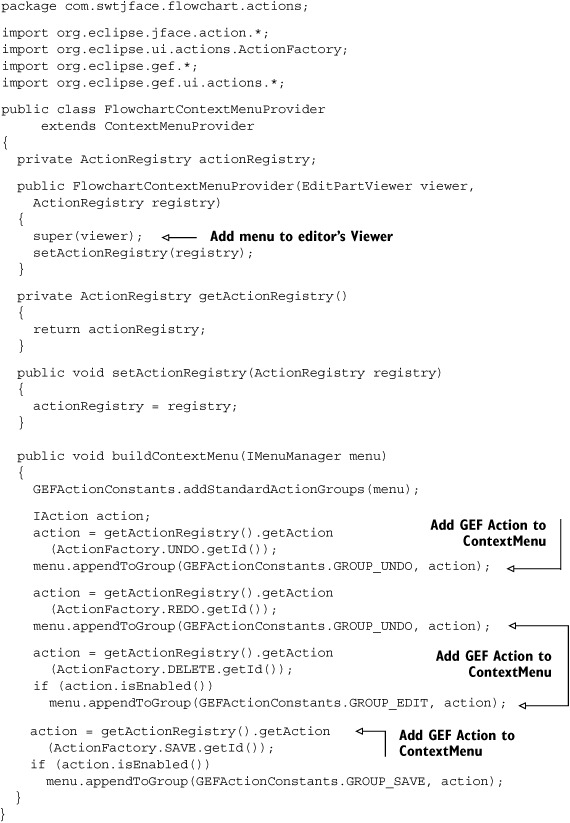
The buildContextMenu() method acquires a MenuManager and searches through the ActionRegistry to find desired Actions. Then, it calls the appendToGroup() method to include them in the context menu.
Context menus are helpful, but it would be more interesting to include our Actions in the Eclipse Workbench. To accomplish this, we need to use a new kind of Action.
D.8.2. Redirecting Workbench actions with RetargetAction
The Eclipse Workbench contains a number of global Actions that can be triggered through its main menu and toolbar. We’d like to redirect them to allow users to perform editing in our editor and use Actions such as Undo, Redo, and Delete.
The process is simple. First, we need to create a set of RetargetActions and add them to the editor’s ActionRegistry. Then, these Actions must be made available to the user. All of this can be accomplished with one class: ActionBarContributor.
RetargetActions
RetargetActions function by directing the effects of the Workbench’s internal Actions to an application. When we use one of these Actions, its corresponding menu option is available for our editor. For example, when we add the DeleteRetargetAction, the Workbench’s Edit->Delete can be used to delete an EditPart.
Table D.5 shows the RetargetActions provided by the GEF. Our editor uses the DeleteRetargetAction, the CopyRetargetAction, and the UndoTargetAction. There is no SaveRetargetAction because saving an editor’s contents is always directed to the editor being used.
Table D.5. GEF retargetable actions
|
Function |
Label |
|
|---|---|---|
| AlignmentRetargetAction | Aligns EditParts | No |
| CopyRetargetAction | Copies and pastes components | No |
| DeleteRetargetAction | Removes EditParts from the editor | No |
| RedoRetargetAction | Reexecutes the given Command | Yes |
| UndoRetargetAction | Negates the effect of the last Command execution | Yes |
| ZoomInRetargetAction | Focuses on a smaller area within the editor | No |
| ZoomOutRetargetAction | Views a greater area of editor space | No |
The Label column in the table refers to whether the RetargetAction can be given a custom label, which works like a tooltip. Only UndoRetargetAction and RedoRetargetAction are subclasses of LabelRetargetAction; the rest of the RetargetActions retain the label specified by the Workbench.
Because GEF makes RetargetActions so easy to use, we don’t need to create separate classes for them. Instead, we only need a single ActionBarContributor.
The ActionBarContributor class
FlowchartProject’s plugin.xml file specifies its contributorClass field as com.swtjface.Actions.FlowchartActionBarContributor. This tells the Workbench that this class will access and modify its resources. In particular, this class functions by specifying which global Actions should be redirected and how they should be made available to the user.
An ActionBarContributor adds Actions to an application’s main menu or ToolBar/CoolBar. For the flowchart editor, we need to add RetargetActions to the Workbench’s toolbar. The code for the FlowchartActionBarContributor is presented in listing D.27. If you’re coding these classes, we recommend that you add this to the com.swtjface.flowchart.actions package.
Listing D.27. FlowchartActionBarContributor.java
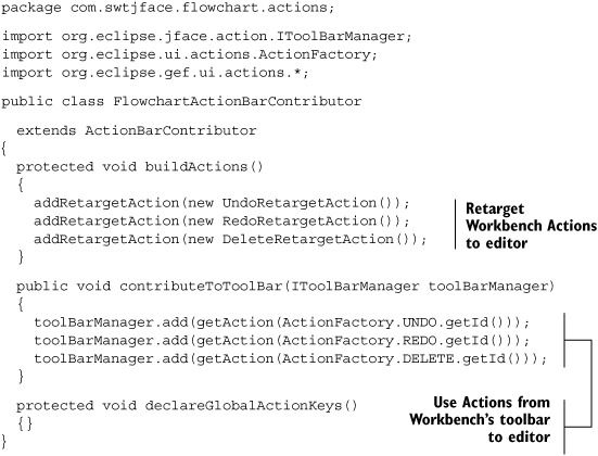
These methods are easy to understand. The buildActions() method updates the ActionRegistry with RetargetActions. Then declareGlobalActionKeys() can be used to match them with keystrokes. The contributeToToolBar() method adds them to the Workbench’s ToolBarManager.
Although the Actions in the flowchart editor are fairly simple, multifunctional editors require many more capabilities. To add them, you need a sound understanding of how the Request-EditPolicy-Command process works. Therefore, instead of discussing a new facet of the GEF, we’ll like to present two detailed, complete examples of how the GEF performs component and connection editing.
D.9. Editing with GEF: two examples
We’ve discussed the GEF’s basic objects and their functions, but you haven’t seen the full editing process from start to finish. Therefore, this section presents two examples that show how a user-generated Event results in a modification to an EditPart’s Model and View aspects. We hope these examples clarify how Tools, EditParts, and Model classes function, and the relationships between them.
D.9.1. Example 1: deleting a component with a keystroke
Users expect that when they click a component and press the Delete key, the component and its connections will disappear. This process is is simple and obvious to the user, but it takes some time to understand what’s going on under the hood.
1: EditorPart sends user-initiated event to Tool
The process of deleting a component has two Events. First, the component needs to be selected. This could result from a number of actions, but we’ll assume the user pressed and lifted her mouse button on the component. Next is a KeyEvent fired by the Delete key.
The editor’s LightWeightSystem forwards the MouseEvent to the editor’s EditDomain. The EditDomain determines which Tool should receive the Event and invokes the Tool’s mouseDown() method. In our example, the EditDomain transfers the MouseEvent to the SelectionTool. When the SelectionTool receives it, it determines whether the cursor was over an EditPart. If so, it sends the EditPart a SelectionRequest by invoking the part’s getCommand(Request) method.
2: KeyHandler receives Delete keystroke and responds
Once the EditPart is selected, the SelectionTool receives the Delete keystroke and calls its KeyDown() method. However, this tool can’t recognize the Delete key, so its method returns false.
But when the user releases the Delete key, the SelectionTool calls its KeyUp() method, which sends the key to the editor’s KeyHandler. This object has already been initialized with a HashMap containing pairs of keys and Action objects. Therefore, it understands that the Delete key corresponds to a DeleteAction. Once the KeyHandler matches the two, it invokes the DeleteAction’s run() method to execute the Action.
3: DeleteAction sends DeleteRequest to part
The DeleteAction’s run() method invokes its createRequest() method to generate a DeleteRequest. It sends the Request object to the selected EditPart by invoking the part’s getCommand(Request) method with a DeleteRequest. If multiple EditParts have been selected for deletion, then a DeleteRequest is sent to each.
4: EditPart determines which EditPolicy to use
When its getCommand() method is invoked, the EditPart accesses its List of EditPolicys, which was populated with createEditPolicies(). The EditPart then calls the getCommand() method contained in each of its EditPolicy classes, and if any can accept the DeleteRequest, it returns a Command object. Those that can’t do so return null. If multiple EditPolicys return a Command, the EditPart combines them using the chain() method contained in the Command class.
5: Policy returns DeleteCommand to delete EditPart
When the EditPart has finished cycling through its available policies, its getCommand() method completes; it returns a DeleteCommand object if any of these policies were able to interpret the DeleteRequest. If so, the execute() method of the DeleteCommand is called. In our code, this method removes the Connection objects associated with the EditPart. Then, it invokes the parent’s removeChild() method.
6: EditPart’s parent deactivates part
When its removeChild() method is called, the parent Model object removes the child EditPart from its list of children and fires a PropertyChangeEvent. The parent’s EditPart responds by calling propertyChange(). In our editor, this method invokes refreshChildren().
This method searches through the parent’s List of child Models and their EditParts. Since the deleted part’s Model has been removed, the parent invokes removeChild(), which calls the part’s deactivate() and removeNotify() methods. These methods tell the part to remove its ConnectionEditParts and children. Finally, the parent’s removeChildVisual() method removes the child’s Figure from the editor.
D.9.2. Example 2: how connections are created
To further describe GEF’s Event-Request-Policy-Command-PropertyChangeEvent methodology, this subsection will present a second example involving connections between EditParts. So far, we’ve created a great deal of code that creates and manipulates these objects, but we haven’t described their interrelated activity.
1: User’s palette selection creates Tool
Users start the process by clicking the ConnectionCreationToolEntry in the FlowchartPalette. Doing so creates a ConnectionCreationTool object, which now handles all external events.
2: User chooses an EditPart as connection source
If the user clicks an EditPart, the ConnectionCreationTool creates a CreateConnectionRequest and initializes it with the location of the mouse click. The tool then determines which part has been targeted and sends the request by invoking the part’s getCommand() method.
3: CreateConnectionRequest becomes a Command
When the Editpart receives the request from the tool, it searches its policies in the EditPolicyIterator to see if any can respond. In the case of our flowchart editor, the NodePolicy, a subclass of GraphicalNodeEditPolicy, starts the response by creating a PathCommand and initializing its parameters. These four parameters are as follows:
- The Path object, which holds the connection information
- The Activity object from which the connection starts (source)
- The ActivityPart’s ConnectionAnchor
- The String name used to represent the ConnectionAnchor
To initialize the first two fields, the tool creates a new Path object and uses the selected ActivityPart as the source. Getting the third and fourth fields is more involved.
This process starts by invoking the part’s getConnectionAnchor() method with the location of the selection. This method calls getConnectionAnchorAt() method in the Activity class, which returns the anchor object. To match the anchor to the terminal name, the policy calls the ActivityPart’s mapConnectionAnchorToTerminal() method, which finds the terminal by calling the ActivityFigure’s getConnectionAnchorName() method. Once the command is fully initialized with the anchor and terminal, it’s sent to the ConnectionCreationTool as the return value of the getCommand() method.
It’s important to understand that this Command won’t be executed immediately. Instead, it’s stored in the startCommand field of the request and is executed after the second EditPart has been selected.
4: Tool creates new Path object
When the ConnectionCreationTool receives the command, it sets the editor’s state to STATE_CONNECTION_STARTED. Then, it uses its handleMove() method to update the editor’s appearance. This means creating a Path object between the source’s anchor and the current mouse position. The process of providing this graphical update, or feedback, begins with invoking the source ActivityPart’s showSourceFeedback() method with a new CreateConnectionRequest. The part passes this request to its policies and, by default, invokes the showSourceFeedback() method of the GraphicalNodeEditPolicy. This method calls the createDummyConnection() method of our NodePolicy, which returns the new Path object.
5: User moves mouse and chooses second EditPart
As the user moves the pointer, the ConnectionCreationTool continually checks whether the mouse is pointing to an EditPart. If so, the target Activity provides feedback by moving the Connection’s endpoint to one of its ConnectionAnchors. The tool also sends the part an updated ConnectionRequest by invoking the part’s getCommand() method.
As before, the request is sent to the target part’s ActivityPolicy, which updates the PathCommand created by the source part. This update involves setting the Command’s target field equal to the target Activity and setting the targetName field equal to name of the target’s ConnectionAnchor.
If the user clicks a second EditPart, then the tool changes the state from STATE_CONNECTION_STARTED to STATE_TERMINAL. It also erases the dummy PolylineConnection and begins creating the connection.
6: PathCommand executes
The PathCommand’s execute() method creates the Connection. First, it sets the Path’s source, sourceName, target, and targetName fields equal to the source Activity, the name of the source’s ConnectionAnchor, the target Activity, and the name of the target’s ConnectionAnchor, respectively. Finally, it informs the source and target that they’re the source and target of a new connection.
Both the source and target Activities fire PropertyChangeEvents, and their ActivityParts respond by invoking refreshSourceConnections() and refreshTargetConnections(). Since these parts have Path objects without PathParts, this method creates PathParts using the PartFactory.
Now that you have a thorough understanding of Tools, Actions, Requests, EditPolicys, and Commands, it’s time to work with the class that brings them all together. The next section deals with the EditorPart.
D.10. Introducing the EditorPart
If you’ve come this far, you have our respect. Learning how GEF operates is difficult, but you’re near the end of the road. We’re now going to discuss the object that brings everything together: EditorPart. This section will cover this class and the GraphicalViewer that does most of the work. We’ll finish by showing the final code for the FlowchartEditor.
D.10.1. Working with EditorParts and GraphicalEditors
Graphical components in the Eclipse Workbench are divided into views and editors. Views, which extend the ViewPart class, organize and display information about the Workbench. Editors function by allowing the user to manipulate and save files; they descend from the EditorPart class.
Both EditorPart and its superclass, WorkbenchPart, are abstract classes with abstract methods. Therefore, if you’re seeking to build an Eclipse editor, you must provide code for each of these methods, shown in table D.6.
Table D.6. Abstract methods of the WorkbenchPart and EditorPart classes
|
Method |
Function |
|---|---|
| WorkbenchPart.createPartControl (Composite) | Specifies the Composite control that provides the editor’s appearance |
| WorkbenchPart.setFocus() | Gives the focus property to the editor |
| EditorPart.init(IEditorSite, IEditorInput) | Initializes the editor with the given location and input (file) |
| EditorPart.isDirty() | Returns whether the editor content has changed |
| EditorPart.doSave (ProgressMonitor) | Specifies actions when editor content is saved to its file |
| EditorPart.doSaveAs() | Specifies actions when editor content is saved to a new file |
| EditorPart.isSaveAllowed() | Specifies whether the SaveAs operation is enabled |
| EditorPart.gotoMarker() | Changes the selection based on the presence of markers |
The two most important of these are init() and createPartControl(). The Workbench calls init() when the user opens a file with the supported extension. Then, to display the editor, the workbench calls createPartControl(). Like the createContents() method of a JFace Window, this method embodies the editor’s appearance within a Composite object.
The nature of this Composite determines how the editor looks and acts. For text editors, this is one large Text box. Graphical editors use a Canvas, but there’s much more to a graphical editor than this object. To provide added functionality, GEF supplies an EditorPart subclass, GraphicalEditor.
The documentation recommends using the GraphicalEditor class as a reference, but we’ll directly integrate one in our flowchart editor. This class provides a number of important capabilities to the editor, such as an ActionRegistry, a CommandStack, an EditDomain, and a SelectionSynchronizer to coordinate selections across multiple viewers. Its most important feature is the GraphicalViewer, which accomplishes the main work of a GEF editor.
D.10.2. Understanding the GraphicalViewer
Earlier, we mentioned that JFace Viewers serve as adapters for Widgets and can simplify and extend the capabilities of their underlying components. Therefore, you can think of a GEF editor as a GraphicalViewer on top of a Canvas object. It handles events, keeps track of the user’s selections, and creates the basis for the editor’s EditPart hierarchy.
Our editor’s Viewer extends GraphicalViewerImpl, a concrete class that implements the GraphicalViewer interface. The best way to see how this object works is to examine its methods, shown in table D.7.
Table D.7. Important methods of the GraphicalViewerImpl class
|
Method |
Function |
|---|---|
| createControl() | Constructs the Canvas beneath the graphical editor |
| createLightweightSystem() | Builds the Draw2D object to handle events and Figures |
| setRootEditPart() | Creates the EditPart that activates all its children |
| setRootFigure() | Specifies the top-level Figure for this editor |
| setContents() | Specifies the top-level Model class for the editor (Chart) |
| getEditPartFactory() | Finds the class to create an EditPart based on its Model |
| addDragSourceListener() | Keeps track of components being moved |
| addDropTargetListener() | Keeps track of components being dropped |
| setKeyHandler() | Keeps track of the user’s keystrokes |
| addSelectionChangedListener() | Listens for changes in the user’s selection |
| findObjectAtExcluding() | Determines which EditPart was selected by the user |
| getSelectedEditParts() | Obtains a list of the EditParts in the selection |
The first two methods create the structure underlying the GEF editor. First, the createControl() method builds the SWT Canvas object. Afterward, it creates a LightWeightSystem to hold the editor’s Draw2D Figures. These objects also provide a channel through which the Viewer can receive Events.
The next two methods provide a basis for the editor’s MVC structure. First, the setRootEditPart() creates a new top-level parent for the EditPart hierarchy. It’s important to understand that this is not a part that we’ve created previously. It doesn’t perform event handling or specify EditPolicys; it does interact with the editor’s Layers, but its main purpose is to manage child EditParts.
Another purpose of the RootEditPart is to specify a Figure to create when setRootFigure() is invoked. Again, this isn’t a Figure that we’ve coded. The nature of this Figure depends on the RootEditPart. In our case, because we’re using a ScalableRootEditPart, the Viewer creates a new Viewport with a LayeredPane.
The next two methods continue this MVC development. The getContents() method initializes the Viewer by providing the top-level Model class of the Viewer. In our case, this is a Chart. The class returned by getEditFactory() uses this Model to create a new EditPart, or a ChartPart for our editor. This EditPart is then added as a child of the Viewer’s RootEditPart.
The next four methods handle events in the Viewer. The first method directs Events from the LightWeightSystem to the editor’s EditDomain. The Viewer creates Listeners for DragEvents and DropTargetEvents and also provides a KeyHandler to respond to keyboard actions. It’s important to note that the Viewer doesn’t respond to Events itself, but sends them to the object best suited to handle them.
The last three methods in the table deal with the Viewer’s management of selections. The Viewer listens for the user’s selections and calls the findObjectAtExcluding() method to see if a selection location matches that of an EditPart. If so, the EditPart is added to the List of EditParts returned by getSelectedEditParts(). Even though the SelectionTool responds to the user’s selection, it gets its information from the Viewer.
D.10.3. The FlowchartEditor
Now that you understand how GraphicalEditors and GraphicalViewers operate, we can present the complete code for the FlowchartEditor. This class extends the GraphicalViewerWithPalette class, which is just a GraphicalEditor with the Composite split into two sections. The code is shown in listing D.28.
Listing D.28. FlowchartEditor.java
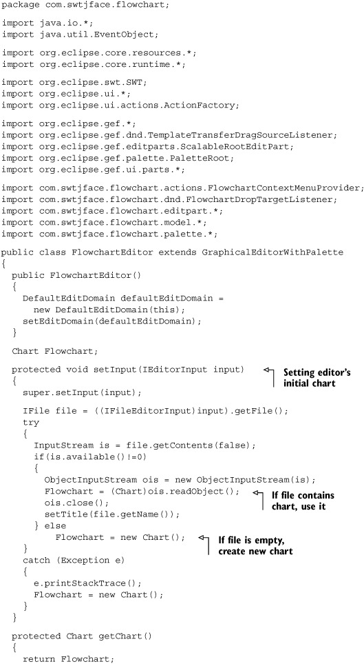
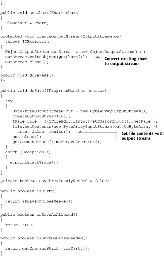
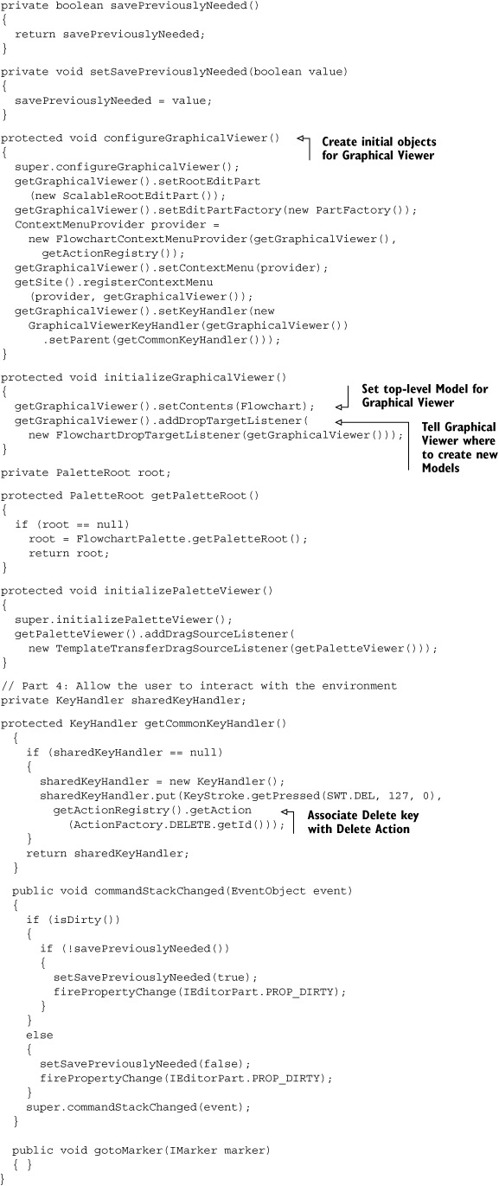
Whew! As shown by the annotations, this class performs three tasks. The first involves file operations. Once the user starts the editor by selecting a *.fcf file, the editor converts it into an ObjectInputStream and attempts to convert this into a Chart object. If the conversion succeeds, then this Chart is used to initialize the GraphicalViewer. Otherwise, if the file is empty, the editor constructs a new Chart object. Similarly, when the user wants to save the Chart to a file, the editor converts it into an ObjectOutputStream and then to a file. Notice that the editor constantly monitors the CommandStack to see if the contents are dirty, which means they’ve been changed since the last save.
The next task involves configuring and initializing the GraphicalViewer and PaletteViewer. The editor provides the GraphicalViewer with its RootEditPart, its EditPartFactory, ContextMenu, and KeyHandler, and initializes it with the Chart. To enable the user to drag template objects from the palette, the editor provides a TemplateTransferDragSourceListener for the PaletteViewer and a FlowchartDropTargetListener for the GraphicalViewer. It also initializes the PaletteViewer with the PaletteRoot created in the FlowchartPalette class.
Finally, the editor manages user input. This means creating a KeyHandler and making sure the Delete keystroke creates a DeleteAction. The editor also responds to Command execution by firing a PropertyChangeEvent whenever the CommandStack changes.
And that finishes our flowchart editor. With luck, your application should resemble figure D.15.
Figure D.15. The flowchart editor in full

D.11. Other GEF aspects
Despite the lengthy presentation, the GEF provides a number of important features that we failed to mention. We’ll talk about these subjects in this final section.
D.11.1. Accessibility
We’re ashamed that we failed to make the flowchart editor accessible, especially since the GEF makes accessibility so easy. GEF EditParts interact with accessibility tools by creating an AccessibilityEditPart() method and making it available. This new EditPart responds to AccessibilityEvents and AccessibilityControlEvents by providing information concerning the part’s name, description, state, and children. AccessibleAnchors make it possible to create and remove Connections through the keyboard.
D.11.2. Grid layout
One of the most interesting features of a GEF editor is the possibility of adding rulers and a grid to the GraphicalViewer. This lets the user force the editor’s Figures to position themselves according to the grid’s points, a process also called SnapToGrid. Once the GridLayout is specified, Actions such as the ToggleSnapToGeometryAction cause EditParts to change their location in response to SnapMoveRequests and SnapResizeRequests.
D.11.3. Zooming in and out
Another interesting capability lets the user increase or decrease the size of a selected portion of the editor through zooming. This is accomplished by a ZoomManager, which is associated with the GraphicalViewer and fires a ZoomEvent when the user changes the zoom level. This Event results in a ZoomInAction or ZoomOutAction, which causes the Viewer to enlarge or reduce the component’s graphics. These Actions can also be performed through the Workbench by adding their RetargetActions.
D.11.4. Kudos to Randy Hudson
The inspiration for our flowchart editor was the Logic Editor created by Randy Hudson, technical lead for IBM’s GEF development and the driving force behind its improvement. Like a latter-day Prometheus, he took this powerful tool out of IBM’s cloistered research group and made it freely available for us commoners.
We’d like to doff our hats to Mr. Hudson for his hard work in both developing and supporting this toolkit, and to you, gentle reader, for your patience in learning how it works.