
4
COMPUTER PROGRAMS AND LANGUAGES
Chapter Outline
4.1 INTRODUCTION
Computer has emerged as the most useful machine in recent times. It can perform wide variety of tasks like receiving data, processing it, and producing useful results. However, being a machine, the computer cannot perform on its own. It needs to be instructed to perform even a simple task like adding two numbers. Computers work on a set of instructions called computer program, which clearly specifies the ways to carry out a task. An analogy of this may be thought of as the instructions given by the manager or team leader to his/her team. The team members follow those instructions and accordingly perform their duties. Similarly, a computer also takes instructions, in the form of computer programs, and carries out the requested task.
Now the question arises that how human beings instruct computers. We, as human beings, use natural languages such as English, Spanish, or French to communicate. Similarly, a user communicates with the computer in a language understood by it. Note that human beings cannot interact directly with the computer using natural languages because, thus far, we have not developed such computers that can comprehend natural languages. Rather, the instructions, provided in the form of computer programs, are developed using computer or programming languages. This chapter discusses some of the most prominent concepts related to computer programming and languages.
4.2 DEVELOPING A COMPUTER PROGRAM
As discussed earlier, a computer program consists of a series of instructions that a computer processes to perform the required operation. In addition, it also includes some fixed data, required to perform the instructions, and the process of defining those instructions and data. Thus, in order to develop a program, a programmer must determine three basic rudiments:
- The instructions to be performed.
- The order in which those instructions are to be performed.
- The data required to perform those instructions.
To perform a task using a program, a programmer has to consider various inputs of the program along with the process, which is required to convert the input into the desired output. Suppose we want to calculate the sum of two numbers, A and B, and store the sum in C. Here, A and B are the inputs, addition is the process, and C is the output of the program as shown in Figure 4.1. Development of a Program
FACT FILE
Development of a Program
A program is a set of instructions that instructs a computer how to perform a specific task. It is written in a high-level language that can be implemented on a number of different processors. A collection of programs can be compared with a recipe book, where each recipe can be assumed as a program. Every recipe has a list of ingredients (fixed data) and a list of instructions detailing exactly what to do with those ingredients. When you follow a recipe, you are actually executing a program.
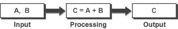
Figure 4.1 Program Performing a Task
4.2.1 PROGRAM DEVELOPMENT CYCLE
Before starting the process of writing a program (coding), the programmer has to determine the problem that needs to be solved. There are different approaches to problem-solving. Most require breaking the problem into a series of smaller steps, independent of the programming language. One common technique is to use the program development cycle, with the number of steps that may vary according to the person who has formalised the development. Often the process runs in a loop because as the current process is completed, new demands appear and the development process commences again. Development cycle of a program includes the following phases:
- Analyse/Define the Problem: In this phase, the problem is analysed precisely and completely. Based on his understanding, the developer knows about the scope within which the problem needs to be developed.
- Task Analysis: After analysing the problem, the developer needs to develop various solutions to solve the given problem. From these solutions, the optimum solution (by experimenting with all the solutions) is chosen, which can solve the problem comfortably and economically.
- Developing Algorithm: After selecting the appropriate solution, algorithm is developed to depict the basic logic of the selected solution. An algorithm depicts the solution in logical steps (sequence of instructions). Further, algorithm is represented by flowcharts and pseudocodes. These tools make program logic clear and they eventually help in coding.
- Testing the Algorithm for Accuracy: Before converting the algorithms into actual code, it should be checked for accuracy. The main purpose of checking algorithm is to identify major logical errors at an early stage, because logical errors are often difficult to detect and correct at later stages. The testing also ensures that the algorithm is a ‘true’ one and it should work for both normal as well as unusual data.
- Coding: After meeting all the design considerations, the actual coding of the program takes place in the chosen programming language. Depending upon application domain and available resources, a program can be written by using computer languages of different levels such as machine, assembly, or high-level languages.
- Test and Debug the Program: It is not unusual for the initial program code to contain errors. The errors may be in the form of logical errors (also known as semantic errors) or incorrect use of programming language (grammatical errors also known as syntax errors). A program compiler and programmer-designed test data machine tests the code for syntax errors. The results obtained are compared with results calculated manually from this test data. Depending upon the complexity of the program, several rounds of testing may be required.
- Documentation: Once the program is free from all the errors, it is the duty of the program developers to ensure that the program is supported by suitable documentation. These documents should be supplied to the program users. Documenting a program enables the user to operate the program correctly. It also enables other persons to understand the program clearly so that it may, if necessary, be modified or corrected by someone other than the original programmer.
- Implementation: After performing all the above-mentioned steps, the program is installed on the end user's machine. The user is also provided with all the essential documents so that he can understand how the program works. The implementation can be viewed as the final testing because only after using the program, the user can point out the drawbacks, if any, to the developers. Based on the feedback, the programmers can modify or enhance the program.
- Maintenance and Enhancement: After the program is implemented, it should be properly maintained taking care of the changing requirements of its users and system. The program should be regularly enhanced by adding additional capabilities. This phase is also concerned with detecting and fixing the errors, which were missed in testing phase. Since this step generates user feedback, the programming cycle continues as the program is modified or reconstructed to meet the changing needs.
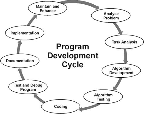
Figure 4.2 Program Development Cycle
4.3 ALGORITHM
Algorithms are one of the most basic tools that are used to develop the problem-solving logic. An algorithm is defined as a finite sequence of explicit instructions that, when provided with a set of input values, produces an output and then terminates. To be an algorithm, the steps must be unambiguous and after a finite number of steps the solution of the problem is achieved. However, algorithms can have steps that repeat (iterate) or require decisions (logic and comparison) until the task is completed.
Different algorithms may accomplish the same task, with a different set of instructions, in more or less the same time, space, and efforts. For example, two different recipes for preparing tea, one ‘add the sugar’ while ‘boiling the water’ and the other ‘after boiling the water’ produce the same result. However, performing an algorithm correctly does not guarantee a solution, if the algorithm is flawed or not appropriate to the context. For example, preparing the tea algorithm will fail if there are no tealeaves present; even if all the steps of preparing the tea are performed as if the tea leaves were there. Consciously or subconsciously, we use algorithms in our daily life. Here are some sample algorithms.
THINGS TO REMEMBER
Algorithm Properties
Algorithms are not computer programs, as they cannot be executed by a computer. Some properties of algorithm are:
- There must be no ambiguity in any instruction.
- There should not be any uncertainty about which instruction is to be executed next.
- The description of the algorithm must be finite. An algorithm cannot be open-ended.
- The execution of the algorithm should conclude after a finite number of steps.
- The algorithm must be general enough to deal with any contingency.
Algorithm 4.1 To Determine Largest of Three Numbers
- Start
- Read three numbers A, B, C
- Find the larger number between A and B and store it in MAX_AB
- Find the larger number between MAX_AB and C and store it in MAX
- Display MAX
- Stop
Algorithm 4.1 terminates after six steps. This explains the feature of finiteness. Every action of the algorithm is precisely defined; hence, there is no scope of ambiguity.
Algorithm 4.2: To Find Average of N Numbers
- Start
- Initialise Total_Num, Num, Sum, and Average to zero
- Read how many numbers and store it in Total_Num
- While numbers to be added are less than Total_Num, follow these two sub tasks repeatedly Read number and store it in Num Add Num to Sum (Sum = Sum + Num)
- Calculate Average = Sum/Total_Num
- Display the Average
- Stop
The need of algorithms can be understood as it provides a logical structure to plan the solution. Once the solution is properly designed, the only job left is to code that logic into the respective programming language. For developing an effective algorithm, flowcharts are used by programmers, which are further expressed in programming language to develop computer programs.
4.4 FLOWCHART
A flowchart is a pictorial representation of an algorithm in which the steps are drawn in the form of different shapes of boxes and the logical flow is indicated by interconnecting arrows. The boxes represent operations and the arrows represent the sequence in which the operations are implemented. The primary purpose of the flowchart is to help the programmer in understanding the logic of the program. Therefore, it is always not necessary to include all the required steps in detail. Flowcharts outline the general procedure. Since they provide an alternative, visual way of representing the information flow in a program, program developers often find them very valuable.
Flowcharts can be compared with the blueprint of a building. Just as an architect draws a blueprint before starting construction of a building, a programmer draws a flowchart prior to writing a computer program. As in the case of the drawing of a blueprint, the flowchart is drawn according to defined rules and using standard flowchart symbols prescribed by the American National Standard Institute (ANSI).
4.4.1 IMPORTANCE OF FLOWCHARTS
A flowchart helps to clarify how things are currently working and how they could be improved. It also assists in finding the key elements of a process, while drawing clear lines between where one process ends and the next one starts. Developing a flowchart encourages communication among participants and establishes a common understanding between them about the process. Flowcharts also help in revealing redundant or misplaced steps. In addition, flowcharts are used to identify appropriate team members by identifying who provides inputs or to whom the resources are to be allocated. It also helps in establishing important areas for monitoring or data collection and to identify areas for improvement or increase in efficiency. The reasons for using flowcharts as a problem-solving tool are given below.
- Makes Logic Clear: The main advantage of using a flowchart to plan a task is that it provides a pictorial representation of the task, which makes the logic easier to follow. The symbols are connected in such a way that they show the movement (flow) of information through the system visibly. The steps and how each step is connected to the next can be clearly seen. Even less experienced personnel can trace the actions represented by a flowchart, that is, flowcharts are ideal for visualising fundamental control structures employed in computer programming.
- Communication: Being a graphical representation of a problem-solving logic, flowcharts are a better way of communicating the logic of a system to all concerned. That is, the diagrammatical representation of logic is easier to communicate to all the interested parties as compared to actual program code as the users may not be aware of all the programming techniques and jargons.
- Effective Analysis: With the help of a flowchart, a problem can be analysed in an effective way. This is because the analysing duties of the programmers can be delegated to other persons, who may or may not know the programming techniques, as they have a broad idea about the logic. Being outsiders, they often tend to test and analyse the logic in an unbiased manner.
- Useful in Coding: The flowcharts act as a guide or blueprint during the analysis and program development phase. Once the flowcharts are ready, the programmers can plan the coding process effectively as they know where to begin and where to end, making sure that no steps are omitted. As a result, error free programs are developed in high-level languages and that too at a faster rate.
- Proper Testing and Debugging: By nature, a flowchart helps in detecting the errors in a program, as the developers know exactly what the logic should do. Developers can test various data for a process so that the program can handle every contingency.
- Appropriate Documentation: Flowcharts serve as a good program documentation tool. Since normally the programs are developed for novice users, they can take the help of the program documentation to know what the program actually does and how to use the program.
4.4.2 FLOWCHART SYMBOLS
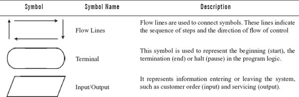
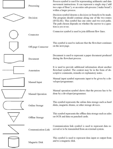
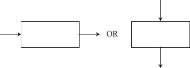
A flowchart uses special shapes to represent different types of actions or steps in a process. Some standard symbols, which are frequently required for flowcharts, are shown in Table 4.1. Note that each symbol has a different shape denoting a different type of operation.
Table 4.1 Flowchart Symbols
4.4.3 GUIDELINES FOR PREPARING FLOWCHARTS
The following guidelines should be used for creating a flowchart:
- The flowchart should be clear, neat, and easy to follow.
- The flowchart must have a logical start and finish.
- In drawing a proper flowchart, all necessary requirements should be listed in logical order.
- The direction of the flow of a procedure should always be from left to right or top to bottom.
- Only one flow line should come out from a process symbol.
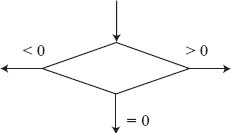
- Only one flow line should enter a decision symbol. However, two or three flow lines (one for each possible answer) may leave the decision symbol.
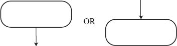
- Only one flow line is used with a terminal symbol.
- Within standard symbols, write briefly. If necessary, use the annotation symbol to describe data or process more clearly.

- In case of complex flowcharts, connector symbols are used to reduce the number of flow lines.
- Intersection of flow lines should be avoided to make it a more effective and better way of representing communication.
- It is useful to test the validity of the flowchart by passing through it with normal/unusual test data.
4.4.4 FLOWCHART STRUCTURES
Flowcharts can be simple, where only few boxes and lines depict the entire logic. They can be complex too, where the logic depiction is really a nightmare. However, no matter how simple or complex the solution is, the following three key constructs are used in drawing a flowchart:
- Sequence, where information can flow in a straight line.
- Selection (branched), where the decisions are made according to some predefined condition.
- Repetition, where the logic can repeat in a loop, that is, where a sequence of steps is repeated until the desired output is obtained.
Sequence Flowchart
As the name implies, in a sequence structure, the instructions to be computed simply follow one another in a logical progression. On a flowchart, the symbol representing each instruction has only a single entering path and a single exiting path. A typical sequence structure (see Figure 4.3) consists of process and input/output steps.
Table 4.2 Sequence Flowchart

In the above example, the first symbol is a Terminal symbol, which is tagged as ‘Start’. This symbol indicates the beginning of the flowchart. The second symbol is an Input/Output symbol, tagged as X=10, Y=20, which indicates the initialisation of two numbers (X and Y) to 10 and 20, respectively. The third symbol is a Processing symbol, labeled as Z = X+Y. In this step, the processing, that is, addition is executed and the sum is stored in a variable, which has given the name Z. The fourth symbol is again an Input/Output symbol, which is labeled as Print Z. This step will print the output (value of Z) on an output device such as monitor. The last symbol, tagged as ‘Stop’, indicates the conclusion of the problem-solving logic.
Selection Flowchart
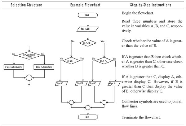
A selection structure allows the program to make a choice between two alternate paths depending on the condition whether it is true or false. The first statement of a selection structure is a conditional statement that obviously involves a decision symbol when represented on a flowchart. Once the sequence of steps in the selected path has been carried out, the paths are rejoined (usually by a connector symbol) and then the next instruction, after the connector, is carried out. Thus, taken as a whole, the selection structure has only a single entry and a single exit. It, therefore, could be represented on a flowchart as a single operational block in a sequence structure.
The flowchart, given in Table 4.3, finds out the maximum of three numbers. Notice that after using the Terminal symbol labeled ‘Start’, the second symbol, that is, Input/Output symbol (Read A, B, C) is used to input three numbers and the values are stored in variables A, B, and C, respectively. The third step involves a Decision symbol, which checks whether the value of A is greater than B. If the condition is true, that is, if A is greater than B, then in the fourth stage, check whether A is also greater than C. However, if the condition is false, that is, if B is greater than A then check whether B is also greater than C. Comparing the values of A and C or B and C also involves Decision symbols. If in the fourth stage, the value of A or B (as the case may be) is greater than C then print the value of A or B otherwise print the value of C. Finally, all the flow lines are joined with a Connector symbol and the flowchart is terminated by a Terminal symbol.
Table 4.3 Selection Flowchart
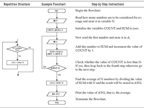
Repetition Flowchart
Repetition or loop pattern causes an interruption in the normal sequence of processing and directs the system to loop back to a previous statement in the program, repeating the same sequence over and again, usually with new data. When a sequence of statements is repeated against a condition, it is said to be in a loop. Using looping, the programmer avoids repeating the same set of instructions. The looping process can be either one time or multiple times until the desired output is obtained within a single program.
The flowchart, shown in Table 4.4, finds out the average of N numbers. Notice that at the beginning of the flowchart, N is taken as an input from the user. Then COUNT and SUM are initialised to zero. After that, the first number is read into A and is added to SUM. After adding the number, the counter (COUNT) is increased by one. The checking is done, that is, if the counter is less than N (which represents the count of numbers to be considered for finding the average) then the same process is repeated. However, if the condition is false, the process breaks out of the loop and the average of N numbers is computed. Finally, the result is printed and the process terminates.
Table 4.4 Repetition Flowchart
4.4.5 SOME SAMPLE FLOWCHARTS
In this section, we present some sample flowcharts that will help you understand to represent the solution to your problems.
Flowchart 4.1: To check whether a given number is even or odd.
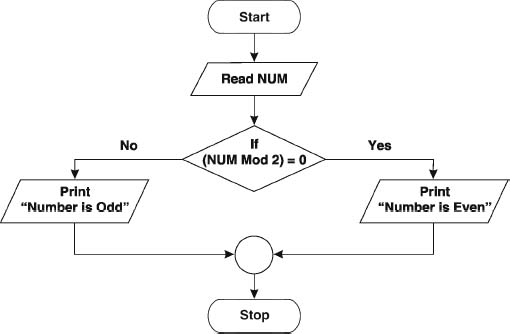
Figure 4.3 Flowchart to Check a Number is Even or Odd
Flowchart 4.2: To compute the sum of first N natural numbers.
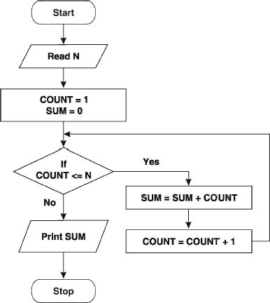
Figure 4.4 Flowchart to Compute Sum of N Natural Numbers
Flowchart 4.3: To compute the factorial of a given number. (Hint: 5! = 5*4*3*2*1=120)
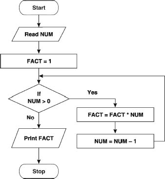
Figure 4.5 Flowchart to Compute the Factorial
Flowchart 4.4: To generate a Fibonacci series upto Nth term. (Hint: Fibonacci series is: 0 1 1 2 3 5 8 13…)
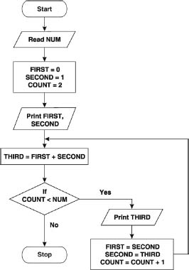
Figure 4.6 Flowchart to Generate Fibonacci Series
4.4.6 LIMITATIONS OF FLOWCHARTS
Flowchart can be used for designing the basic concept of the program in pictorial form but cannot be used for programming purposes. Some of the limitations of the flowchart are given below:
- Complex: The major disadvantage in using flowcharts is that when a program is very large, the flowcharts may continue for many pages, making them hard to follow. Flowcharts tend to get large very quickly and it is difficult to follow the represented process. It is also very laborious to draw a flowchart for a large program. You can very well imagine the nightmare when a flowchart is to be developed for a program, consisting of thousands of statements.
- Costly: Drawing flowcharts are viable only if the problem-solving logic is straightforward and not very lengthy. However, if flowcharts are to be drawn for a huge application, the time and cost factor of program development may get out of proportion, making it a costly affair.
- Difficult to Modify: Due to its symbolic nature, any changes or modification to a flowchart usually requires redrawing the entire logic again, and redrawing a complex flowchart is not a simple task. It is not easy to draw thousands of flow lines and symbols along with proper spacing, especially for a large complex program.
- No Update: Usually programs are updated regularly. However, the corresponding update of flowcharts may not take place, especially in the case of large programs. As a result, the logic used in the flowchart may not match with the actual program's logic. This inconsistency in flowchart update defeats the main purpose of the flowcharts, that is, to give the users the basic idea about the program's logic.
4.5 COMPUTER LANGUAGES
Previously, we discussed that a computer needs to be instructed using computer programs to perform all its tasks, for this, programs are written in special computer languages. A natural language is not used to instruct the computer even though a programming language consists of a set of characters, symbols, and usage rules that allow the user to communicate with computers, just as in natural languages. The main reason behind it is that natural languages (English, Spanish) are ambiguous, vaguely structured, and has very large (and ever changing) vocabularies. Computer languages have relatively few, exactly defined, rules for composition of programs, and strictly controlled vocabularies in which unknown words must be defined before they can be used. A programming language has to follow syntax rules to create an accurate program so that the computer can yield desired results. In case of natural languages, we can understand even while using poor grammar and vocabulary. However, in case of programming language, the rules are very rigid, thus the programmer has to follow all the specified rules.
4.5.1 TYPES OF PROGRAMMING LANGUAGES
Computers understand only one language and that is binary language or the language of 0s and 1s. Binary language is also known as machine or low-level language. In the initial years of computer programming, all the instructions were given in binary form only. Although these programs were easily understood by the computer, it proved too difficult for a normal human being to remember all the instructions in the form of 0s and 1s. Therefore, the computer remained a mystery to a common person until other languages such as assembly and high-level languages were developed which were easier to learn and understand. These languages use commands that have some degree of similarity with English (such as ‘if else’, ‘exit’). Programming languages can be divided into three major categories:
- Machine Language: It is the native language of computers. It uses only 0s and 1s to represent data and the instructions written in this language, consist of series of 0s and 1s.
- Assembly Language: It correspondences symbolic instructions and executable machine codes and was created to use letters instead of 0s and 1s to run a machine.
- High-level Language: These languages are written using a set of words and symbols following some rules similar to a natural language such as English. The programs written in high-level languages are known as source programs and these programs are converted into machine-readable form by using compilers or interpreters.
Note : Together, machine and assembly language are also known as low-level languages.
4.6 GENERATIONS OF COMPUTER LANGUAGES
Since early 1950s, programming languages have evolved tremendously. This evolution has resulted in the development of hundreds of different languages. With each passing year, the languages have become user-friendly and more powerful. We can illustrate the development of all the languages in five generations.
4.6.1 FIRST GENERATION: MACHINE LANGUAGE
The first language was binary, also known as machine language, which was used in the earliest computers and machines. We know that computers are digital devices, which have only two states, ON and OFF (1 and 0). Hence, computers can understand only two binary codes. Therefore, every instruction and data should be written using 0s and 1s. Machine language is also known as the computer's ‘native’ language as this system of codes is directly understood by the computer. Instruction in machine language consists of two parts (see Figure 4.7). The first part is an operation, which tells the computer what functions are to be performed. The second part of the instruction is the operand, which tells the computer where to find or store the data on which the desired operation is to be performed.
A binary program is a long list of instructions that are executed by the CPU. Normally, instructions are executed one after the other, but program flow may be influenced by special jump instructions that transfer execution to an instruction other than the following one. Each computer has its own set of instructions based on its architecture. Hence, machine language may differ from computer to computer.

Figure 4.7 Machine Language Instruction Format
THINGS TO REMEMBER
First Programmers
Lady Lovelace Ada Augusta (officially the first programmer) suggested binary numbers for computer storage instead of decimals. A British mathematician, Alan Mathison Turing, was the first person to recognise that programming in machine language is less time consuming. In 1952, John von Neuman proposed to have new programs loaded from a magnetic tape to read. With differences in magnetic polarities, it can mean either ON or OFF states.
Advantages of Machine Language
Even though machine language is not a human friendly language, it offers following advantages:
- Translation Free: Machine language is the only language that computers can directly execute without the need for conversion. Even an application using high-level languages, has to be converted into machine-readable form so that the computer can understand the instructions.
- High Speed: Since no conversion is needed, the applications developed using machine languages are extremely fast. It is usually used for complex applications such as space control system, nuclear reactors, and chemical processing.
Disadvantages of Machine Language
There are many disadvantages in using machine language to develop programs. Some of these are given below:
- Machine Dependent: Every computer type differs from the other, based on its architecture. Hence, an application developed for a particular type of computer may not run on the other type of computer. This may prove costly as well as difficult for the organisations.
- Complex Language: Machine language is very difficult to read and write. Since all the data and instructions must be converted to binary code, it is almost impossible to remember the instructions. A programmer must specify each operation, and the specific location for each piece of data and instruction to be stored. It means that a programmer practically needs to be a hardware expert to have proper control over the machine language.
- Error Prone: Since the programmer has to remember all the opcodes and the memory locations, machine language is bound to be error prone. It requires a super human effort to keep track of the logic of the problem and, therefore, results in frequent programming errors.
- Tedious: Machine language poses real problems while modifying and correcting a program. Sometimes the programming becomes too complex to modify and the programmer has to rewrite the entire logic again. Therefore, it is very tedious and time-consuming, and since time is a precious commodity, programming using the machine language tends to be costly.
Due to its overwhelming limitations, machine language is rarely used nowadays.
4.6.2 SECOND GENERATION: ASSEMBLY LANGUAGE
The complexities of machine language led to the search of another language: the assembly language, developed in the early 1950s and its main developer was IBM. However, Jack Powell, Bob Nevelen, Clement and Michael Bradly also helped in the development of the assembly language. It was a stepping-stone for all subsequent language development. Assembly language allows the programmer to interact directly with the hardware. This language assigns a mnemonic code to each machine language instruction to make it easier to remember or write. It allows better human-readable method of writing programs as compared to writing in binary bit patterns. However, unlike other programming languages, assembly language is not a single language, but a group of languages. Each processor family (and sometimes individual processors within a processor family) has its own assembly language.
An assembly language provides a mnemonic instruction, usually three letters long, corresponding to each machine instruction. The letters are usually abbreviated indicating what the instruction does. For example, ADD is used to perform an addition operation, MUL for multiplication, and so on. Assembly languages make it easier for humans to remember how to write instructions to the computer, but an assembly language is still a representation of the computer's native instruction set. Since each type of computer uses a different native instruction set, assembly languages cannot be standardised from one machine to another, and instructions for one computer cannot be expected to work on another.
The basic unit of an assembly language program is a line of code. It allows the use of symbols and set of rules that can be used and combined to form a line of code. Each line of an assembly language program consists of four columns called fields. The general format of an assembly instruction is:
[Label] <Opcode> <Operands> [; Comment]
[…] brackets indicate that enclosed specification may or may not appear in a statement. If a label is specified, it is associated as a symbolic name with the machine words generated for the assembly statement. If multiple operands are used, each of them is separated by a comma. The text after semicolon (;) is just comments. Comments are not a part of actual program, but are used just for reference purposes, that is, to specify what the statement actually will do. Although comments are optional, they are included to facilitate proper documentation. For example,
![]()
Note : The first character of an assembly language variable should be an alphabet. The rest of the characters may be alphabets or digits. However, the total number of characters should not exceed 8.
Assembler
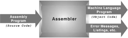
This language is nothing more than a symbolic representation of machine code, which allows symbolic designation of memory locations. However, no matter how close assembly language is to machine code, the computer still cannot understand it. The assembly language program must be translated into machine code by a separate program called an assembler. The assembler program recognises the character strings that make up the symbolic names of the various machine operations, and substitutes the required machine code for each instruction. At the same time, it also calculates the required address in memory for each symbolic name of a memory location, and substitutes those addresses for the names resulting in a machine language program that can run on its own at any time. In short, an assembler converts the assembly codes into binary codes and then it assembles the machine understandable code into the main memory of the computer, making it ready for execution.
The original assembly language program is also known as the source code, while the final machine language program is designated as the object code. If an assembly language program needs to be changed or corrected, it is necessary to make the changes to the source code and then re-assemble it to create a new object program. The functions of an assembler are given below:
- It allows the programmer to use mnemonics while writing source code programs, which are easier to read and follow.
- It allows the variables to be represented by symbolic names, not as memory locations.
- It translates mnemonic operations codes to machine code and corresponding register addresses to system addresses.
- It checks the syntax of the assembly program and generates diagnostic messages on syntax errors.
- It assembles all the instructions in the main memory for execution.
Figure 4.8 Working of an Assembler
- In case of large assembly programs, it also provides linking facility among the subroutines.
- It facilitates the generation of output on required output medium.
Advantages of Assembly Language
The advantages of using assembly language to develop a program are given below:
- Easy to Understand and Use: Assembly language uses mnemonics instead of using numerical opcodes and memory locations used in machine language. Hence, the programs written in assembly language are much easier to understand and use as compared to its machine language counterpart. Being a more user-friendly language as compared to machine language, assembly programs are easier to modify.
- Less Error Prone: Since mnemonic codes and symbolic addresses are used, the programmer does not have to keep track of the storage locations of the information and instructions. Hence, there are fewer errors while writing an assembly language program. Even in case of errors, assembly programs provide better facility to locate and correct them as compared to machine language programs. Moreover, assemblers also provide various mechanisms to locate the errors. For example, in case of adding two variables such as ADD A, B, if the variables (A and B) are not defined in the program, the assembler will give an error indicating the same so that the programmer can easily correct the mistake.
- Faster: Assembly programs can run much faster and use less memory and other resources than a similar program written in a high-level language. Speed increment of 2 to 20 times faster is common, and occasionally, an increase of hundreds of times faster is also possible.
- More Control on Hardware: Assembly language also gives direct access to key machine features essential for implementing certain kinds of low-level routines such as an operating system kernel or micro-kernel, device drivers, and machine control.
Disadvantages of Assembly Language
The disadvantages in using assembly language to develop a program are given below:
- Machine Dependent: Different computer architectures have their own machine and assembly languages, which means that programs written in these languages are not portable to other, incompatible systems. This makes it a low-level language. If an assembly program is to be shifted to a different type of computer, it has to be modified to suit the new environment.
- Harder to Learn: The source code for an assembly language is cryptic and in a very low machine-specific form. Being a machine-dependent language, every type of computer architecture requires a different assembly language, making it hard for a programmer to remember and understand every dialect of assembly. More skilled and highly trained programmers, who know all about the logical structure of the computer only, can create applications using assembly language.
- Slow Development Time: Even with highly skilled programmers, assembly generated applications are slower to develop as compared to high-level language based applications. In case of assembly language the development time can be 10 to 100 times as compared to high-level language generated application.
- Less Efficient: A program written in assembly language is less efficient than machine language because every assembly instruction has to be converted into machine language. Therefore, the execution of assembly language program takes more time than machine language program. Moreover, before executing an assembly program, the assembler has to be loaded in the computer's memory for translation and occupies a sizeable memory.
- No Standardisation: Assembly languages cannot be standardised because each type of computer has a different instruction set and, therefore, a different assembly language.
- No Support for Modern Software Engineering Technology: Assembly languages provide no inherent support for software engineering technology. They work with just machine-level specifics, not with abstractions. Assembly language does not provide inherent support for safety-critical systems. It provides very little opportunity for reuse and there is no object-oriented programming support. There is also no specific support for distributed systems. The tools available for working with assembly languages are typically very low-level tools.
4.6.3 THIRD GENERATION: HIGH-LEVEL LANGUAGE
During 1960s, computers started to gain popularity and it became necessary to develop languages that were more like natural languages such as English so that a common user could use the computer efficiently. Since assembly language required deep knowledge of computer architecture, it demanded programming as well as hardware skills to use computers. Due to computer's widespread usage, early 1960s saw the emergence of the third generation programming languages (3GL). Languages such as COBOL, FORTRAN, BASIC, and C are examples of 3GLs and are considered high-level languages.
High-level languages are similar to English language. Programs written using these languages can be machine independent. A single high-level statement can substitute several instructions in machine or assembly language. Unlike assembly and machine programs, high-level programs may be used with different types of computers with little or no modification, thus reducing the re-programming time.
In high-level language, programs are written in a sequence of statements to solve a problem. For example, the following BASIC code snippet will calculate the sum of two numbers:
LET X = 10
LET Y = 20
LET SUM = X + Y
PRINT SUM
The first two statements store 10 in variable X (memory location name) and 20 in variable Y, respectively. The third statement again creates a variable named SUM, which will store the summation of X and Y value. Finally, the output is printed, that is, the value stored in SUM is printed on the screen.
Advantages of High-Level Languages
High-level languages (HLL) are useful in developing complex software, as they support complex data structures. It increases the programmer's productivity (the number of lines of code generated per hour). Unlike assembly language, the programmer does not need to learn the instruction set of each computer being worked with. Various advantages of using high-level languages are given below:
- Readability: Since high-level languages are closer to natural languages, they are easier to learn and understand. In addition, a programmer does not need to be aware of computer architecture; even a common man can use it without much difficulty. This is the main reason of HLL's popularity.
- Machine Independent: High-level languages are machine independent in the sense that a program created using HLL can be used on different platforms with very little or no change at all.
- Easy Debugging: High-level languages include the support for ideas of abstraction so that programmers can concentrate on finding the solution to the problem rapidly, rather than on low-level details of data representation, which results in fewer errors. Moreover, the compilers and interpreters are designed in such a way that they detect and point out the errors instantaneously.
- Easier to Maintain: As compared to low-level languages, the programs written in HLL are easy to modify and maintain because HLL programs are easier to understand.
- Low Development Cost: High-level languages permit faster development of programs. Although a high-level program may not be as efficient as an equivalent low-level program, the savings in programmer's time generally outweighs the inefficiencies of the application. This is because the cost of writing a program is nearly constant for each line of code, regardless of the language. Thus, a high-level language, where each line of code translates to 10 machine instructions, costs only a fraction as compared to program developed in a low-level language.
- Easy Documentation: Since the statements written in HLL are similar to natural languages, they are easier to understand as compared to low-level languages.
Disadvantages of High-Level Languages
The main disadvantages of this language are given below:
- Poor Control on Hardware: High-level languages are developed to ease the pressure on programmers so that they do not have to know the intricacies of hardware. As a result, sometimes the applications written in high-level languages cannot completely harness the total power available at hardware level.
- Less Efficient: The HLL applications are less efficient as far as computation time is concerned. This is because, unlike low-level languages, high-level languages must be created and sent through another processing program known as a compiler. This process of translation increases the execution time of an application. Programs written in high-level languages take more time to execute, and require more memory space. Hence, critical applications are generally written in low-level languages.
4.6.4 FOURTH GENERATION: 4GL
Fourth generation languages (4GLs) have simple, English-like syntax rules, commonly used to access databases. The third generation programming languages are considered as procedural languages because the programmer must list each step and must use logical control structures to indicate the order in which instructions are to be executed. 4GLs, on the other hand, are non-procedural languages. The non-procedural method is simply to state the needed output instead of specifying each step one after another to perform a task. In other words, the computer is instructed what it must do rather than how a computer must perform a task.
The non-procedural method is easier to write, but has less control over how each task is actually performed. When using non-procedural languages, the methods used and the order in which each task is carried out is left to the language itself; the user does not have any control over it. In addition, 4GLs sacrifice computer efficiency in order to make programs easier to write. Hence, they require more computer power and processing time. However, with the increase in power and speed of hardware and with diminishing costs, the uses of 4GLs have spread.
Fourth generation languages have a minimum number of syntax rules. Hence, common people can also use such languages to write application programs. This saves time and allows professional programmers for more complex tasks. The 4GLs are divided into three categories:
- Query Languages: They allow the user to retrieve information from databases by following simple syntax rules. For example, the database may be requested to locate details of all employees drawing a salary of more than $10000. Structured Query Language (SQL) and IBM's Query-By-Example (QBE) are examples of query languages.
- Report Generators: They produce customised reports using data stored in a database. The user specifies the data to be in the report, the report's format, and whether any subtotals and totals are needed. Often report specifications are selected from pull-down menus, making report generators very easy to use. Examples of report generators are Easytrieve Plus by Pansophic and R&R Relational Report Writer by Concentric Data Systems.
- Application Generators: With application generators, the user writes programs to allow data to be entered into the database. The program prompts the user to enter the needed data. Cincom System's MANTIS and ADS by Cullinet are examples of application generators.
Advantages of 4GLs
The main advantage of 4GLs is that a user can create an application in a much shorter time for development and debugging than with other programming languages. The programmer is only interested in what has to be done and that too at a very high level. Being non-procedural in nature, it does not require the programmers to provide the logic to perform a task. As a result, lot of programming effort is saved. Use of procedural templates and data dictionaries allow automatic type checking (for the programmer and for user input) and this results in fewer errors. Using application generators, the routine tasks are automated.
Disadvantages of 4GLs
Since programs written in a 4GL are quite lengthy, they need more disk space and a large memory capacity as compared to 3GLs. These languages are inflexible also because the programmers' control over language and resources is limited as compared to other languages. These languages cannot directly utilise the computer power available at hardware level as compared to other levels of languages.
4.6.5 FIFTH GENERATION: VERY HIGH-LEVEL LANGUAGES
Fifth generation languages are just the conceptual view of what might be the future of programming languages. These languages will be able to process natural languages. The computers would be able to accept, interpret, and execute instructions in the native or natural language of the end users. The users will be free from learning any programming language to communicate with the computers. The programmers may simply type the instruction or simply tell the computer by way of microphones what it needs to do. Since these languages are still in their infancy, only a few are currently commercially available. They are closely linked to artificial intelligence and expert systems.
LET US SUMMARISE
- A computer needs to be instructed to perform all its tasks. These instructions are provided in the form of computer program. Programming involves many stages such as analyse problem, task analysis, algorithm development, algorithm testing, coding, program testing and debugging, documentation, implementation, and maintenance.
- Algorithm is a precise set of instructions, which specify how to solve a problem. An algorithm must be unambiguous and it should reach a result after a finite number of steps.
- Flowchart is a means of visually presenting the flow of control through the system, the operations performed within the system and the sequence in which they are performed. By visualising the process, a flowchart can quickly help identify bottlenecks or inefficiencies where the process can be streamlined or improved.
- There are mainly three key constructs, which are used in drawing a flowchart. These are sequence, selection, and repetition.
- In a sequence structure, the instructions to be computed simply follow one another in a logical progression.
- A selection structure allows the program to make a choice between two alternate paths depending on the condition whether it is true or false.
- Repetition or loop pattern causes an interruption in the normal sequence of processing and directs the system to loop back to a previous statement in the program, repeating the same sequence over and again, usually with new data.
- Programming language is a language that a user employs to interact with the computer. They can be divided into three major categories: machine, assembly, and high-level languages.
- First generation language is the machine language in which instructions are in the form of 0s and 1s.
- Second generation language is the assembly language in which mnemonic code is assigned to each machine language instruction to make it easier to remember and write.
- Third generation languages are machine independent and use language translators to translate the high-level code into machine code.
- Fourth generation languages, also called as non-procedural languages, use minimum syntax rules and are categorised into query languages, report generators, and application generators.
- Fifth generation language is in the development stage where the computer will be able to accept, interpret, and execute the instruction in the natural language of the user.
EXERCISES
Fill in the Blanks
- The sequence of instructions that instruct the computer to carry out a specific task is called ____________.
- The graphical representation of an algorithm is called ____________.
- The process of detecting, isolating, and correcting errors in a computer program is known as ____________.
- A program that translates the assembly language code into machine language code is called ___________.
- The two-part forms of machine language instructions are __________ and __________.
- __________ language is very close to the hardware.
- COBOL, FORTRAN, and C are examples of ___________.
- ___________ allow the user to retrieve information from databases by following simple syntax rules.
- To be an algorithm, the steps must be ____________ and after a finite number of steps, the __________ of the problem is achieved.
- The __________ can be viewed as the final testing because only after using the program, the user can point out the drawbacks, if any, to the developers.
Multiple Choice Questions
- The semantic and syntax errors in the program are checked in
- (a) Coding phase
- (b) Testing phase
- (c) Implementation phase
- (d) Analysis phase
- The diamond shape symbol in the flowchart signifies
- (a) Processing
- (b) Connectors
- (c) Decision
- (d) None of these
- A high-level language is a programming language that is
- (a) Easier to use
- (b) A first generation language
- (c) A third generation language
- (d) Both (a) and (c)
- Which of the following was a disadvantage of the first generation language?
- (a) Machine dependency
- (b) Less efficient
- (c) Need for more disk space
- (d) All the above
- Flow lines in a flowchart are used to connect
- (a) Two terminals
- (b) Two connectors
- (c) Two input/output
- (d) All the above
- Which of the following structures allows the program to make a choice between two alternate paths depending upon the condition?
- (a) Sequence
- (b) Loop
- (c) Selection
- (d) None of the above
- The terminal symbol in a flowchart represents
- (a) Start of program logic
- (b) Manual operation
- (c) Processing
- (d) Decision
- Semantic error occurs due to
- (a) Incorrect syntax
- (b) Incorrect logic
- (c) Wrong inputs
- (d) None of the above
- Query languages come under
- (a) Second generation
- (b) Third generation
- (c) Fifth generation
- (d) Fourth generation
- What consists of instructions written as a string of 1s and 0s?
- (a) Query language
- (b) Assembly language
- (c) Machine language
- (d) None of the above
State True or False
- The graphical representation of an algorithm is called flowchart.
- The generic way of describing an algorithm without the use of programming is known as program.
- The language translator that translates the programs written in high-level language into its corresponding machine code is assembler.
- Machine language is also called as low-level language.
- Documenting a program enables the user to operate the program correctly.
- An algorithm can be open-ended.
- The connector symbol in a flowchart indicates that the flowchart continues on the next page.
- Compilers are used to convert the programs written in high-level languages into machine-readable form.
- Report generator is a category of third generation language.
- Fifth generation languages are closely linked to artificial intelligence and expert systems.
Descriptive Questions
- Explain program development cycle with the help of a block diagram.
- Define an algorithm. List the characteristics of a good algorithm.
- Define a flowchart. List some important reasons for using flowcharts.
- Discuss the three main constructs used while drawing flowcharts along with suitable examples.
- Describe the classification of programming languages.
- Discuss the advantages and disadvantages of the following:
- (a) Machine language
- (b) High-level language
- (c) Assembly language
- (d) Fourth generation language
- What guidelines should be followed while drawing a flowchart?
- Develop an algorithm to compute the sum of the digits of a given number. Draw the flowchart also.
ANSWERS
Fill in the Blanks
- Computer program
- Flowchart
- Debugging
- Assembler
- Opcode, operand
- Machine
- Third generation languages
- Query languages
- Unambiguous, solution
- Implementation
Multiple Choice questions
- (b)
- (c)
- (d)
- (a)
- (d)
- (c)
- (a)
- (b)
- (d)
- (c)
State True or False
- True
- False
- False
- True
- True
- False
- False
- True
- False
- True