
3 Basic concepts of Rotating Machines
Transformers have already been introduced. The transformer is a static device having primary and secondary windings. In rotating machines, there are two parts: the stator and the rotor. Rotating electrical machines are also of two types: DC and AC machines. Electrical machines are widely used. In DC machines the stator is used as a field and the rotor is used as an armature, while reverse is the case for AC machines, that is, synchronous generators and synchronous motors. The induction motor is another kind of AC machine, which is singly excited; that is, AC supply voltage is only given to the stator and no supply is given to the rotor. In DC machines and synchronous machines, the field is always excited by DC supply. DC machines and AC machines have their own advantages and disadvantages. The classification of rotating machines is shown in Figure 3.1.
The aim of this chapter is to introduce the basic concepts of rotating machines.
3.1 ELECTROMAGNETIC TORQUE
Figure 3.2(a) shows a two-pole cylindrical rotor with one conductor. Only the stator magnetic flux path due to excitation of field coils has been shown in Figure 3.2(a), and there is no current in the rotor conductor. Figure 3.2(b) shows the distribution of flux due to current only in the rotor conductor, and there is no excitation in stator field coils. Figure 3.2(c) shows the resultant flux distribution when both field coils and rotor conductors are excited. The rotor conductor experiences a force in the upward direction and torque is produced in the clockwise direction due to interaction between stator and rotor magnetic fields. This torque is known as electromagnetic torque.
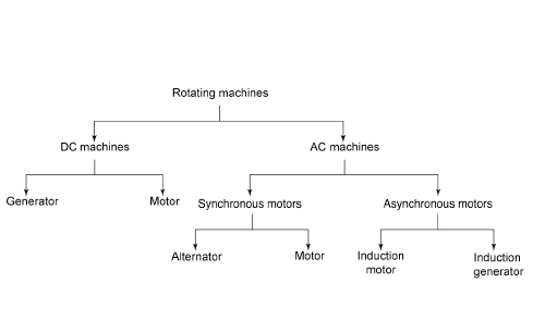
Figure 3.1 Classification of Rotating Machines
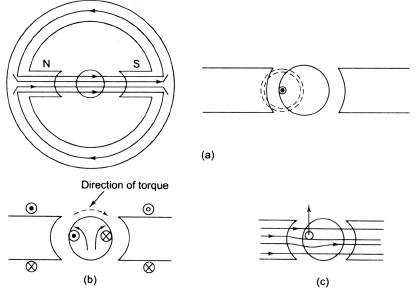
Figure 3.2 Electromagnetic Torque
3.2 RELUCTANCE TORQUE
Figure 3.2(a) shows the magnetic flux path due to current in stator coils. Figure 3.3 shows the stator-produced flux when a ferromagnetic material is placed in this magnetic field. The rotor will immediately experience a counterclockwise torque because the magnetic flux has a tendency to follow a minimum reluctance path. This torque is called reluctance torque. The reluctance torque will be zero when the rotor axis coincides with the stator axis.
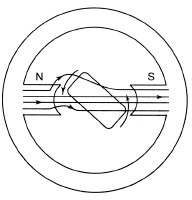
Figure 3.3 Reluctance Torque
3.3 CONSTRUCTIONAL FEATURES OF ROTATING ELECTRICAL MACHINES
Any rotating electrical machine has (i) stator, (ii) rotor, (iii) air gap separating the stator and rotor and (iv) shaft, bearing, foundation and so on, including excitation or field winding. The current in the excitation or field winding does not vary with the load on the machine. This current is also known as magnetizing current, exciting current or field current. The exciting or field winding produces the working flux. The current in the armature winding varies with load. In armature winding emf is induced by the working flux. Since the armature winding handles all the power, the rating of the armature winding is equal to the power rating of the machine. The power rating of the field winding is 0.5–2 per cent of the rated power of the machine. After establishing the field current, the power input to DC field winding is dissipated as I2R loss. The field winding for AC and DC machines must be energized from DC source. In both DC and AC machines, the armature windings deal only with alternating current. Therefore, all rotating electrical machines have laminated armature structure to reduce eddy current loss. To reduce the hysteresis loss, the core material is selected in such a way that it has small hysteresis loop.
3.4 CONSTRUCTION OF DC MACHINES
The construction of DC machines is discussed here. An actual generator consists of the following parts:
- magnetic frame or yoke,
- pole cores and pole shoes,
- armature core,
- armature windings or conductors,
- commutator and
- brushes and bearings.
The yoke, pole cores, armature core and air gaps between the poles and the armature core form the magnetic field. The rest form the electrical circuit. Figure 3.4 shows the construction of a DC machine in which the above parts have been depicted.
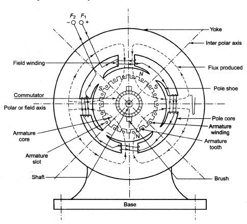
Figure 3.4 Construction of a DC Machine
3.4.1 Magnetic Frame or Yoke
The magnetic frame or yoke gives mechanical support for poles as well as protects the whole machine as a protecting cover. It also carries the magnetic flux produced by the poles. In small generators yokes are made of cast iron, whereas for large machines cast steel is used. The yoke carries 50 per cent of total flux per pole.
3.4.2 Pole Cores and Pole Shoes
The field magnet has two parts: pole cores and pole shoes. The pole shoes spread out the flux in the air gap and reduce the reluctance of the magnetic path due to its large cross-section. The pole shoes support the exciting coils. The pole shoes are made curved to ensure uniform air gap around the armature core.
The following are the functions of pole shoes:
- to support the field coils,
- to reduce the reluctance of the magnetic path and
- to achieve uniform flux distribution around the air gap.
The pole core may be a solid piece and is made out of either cast iron or cast steel, whereas the pole shoe is laminated and fastened to the pole face by countersunk screws, shown in Figure 3.5.
The field coil is rigidly put in position between the frame attached to the yoke and the pole shoe. In modern design, the pole cores and pole shoes are built of thin laminations of annealed steel, where the thickness of lamination varies from 1 mm to 0.25 mm. To secure the laminated poles to yoke, any of the following ways can be used:
- The holding screws may be bolted into the steel bar, and it passes through the pole across the plane of laminations.
- The pole is secured to the yoke by means of screws bolted through the yoke and into the pole body.
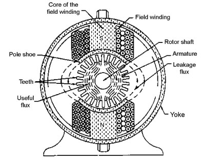
Figure 3.5 Pole Cores and Pole Shoes and Distribution of Magnetic Flux for a Two-pole DC Machine
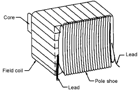
Figure 3.6 Field Coils of a DC Machine
If the air gap is increased, the reluctance will be increased. This causes the machine to draw the more current in case of motoring mode and to give less output power in case of generating mode. The actual flux distribution in the air gap depends on the following factors:
- size of air gap,
- shape of pole shoes and
- clearance between the tips of the adjacent pole shoe.
3.4.3 Pole Coils
The field coils or pole coils consist of high-grade copper or aluminium enamelled wire or strip. These are former wound for the correct dimension. After getting the correct dimension, the former is removed. Now, the wound coil is placed over the core. Figure 3.6 shows the field coils of a DC machine. From Figures 3.5 and 3.6, it can be seen that the field coils are wound in such a way that alternate north and south poles are produced to ensure the correct polarity of the induced emf. To obtain the necessary flux, the current is passed through these coils and the field windings form an electromagnet. The field windings receive current either from an external DC source or from the armature when they connected across it. Due to the flow of current through the field windings, a magnetic flux is established in the yoke, through the pole pieces, in the air gap and in the armature gap, shown in Figure 3.5.
3.4.4 Armature Core
Armature conductors or coils consist of super-enamelled copper wire or strip placed on the armature core, which is cylindrical or drum shaped. Figure 3.7(a) shows the constructional details of an armature, which is mounted on the shaft rotating in the magnetic field. During rotation it cuts the magnetic flux of the field magnets. It also provides a path of very low reluctance to the flux from the north pole to the south pole. The armature core is usually built of circular sheet steel discs or laminations to reduce the eddy current loss. The thickness of laminations varies from 0.3 mm to 1.0 mm. Figure 3.7(b) shows the laminated sheet steel used for the armature core. Perforations exist in these laminations to provide axial flow of air through the armature for cooling purposes and also to reduce the weight. For small machines, these laminations are directly fixed to the shaft. On the other hand, these laminations are assembled on a spider that is fixed to the shaft. The laminations are punched with the slots that house the armature conductors. The armature core is keyed to the shaft. The sheets of insulations are provided in the slots between the core and the conductors.
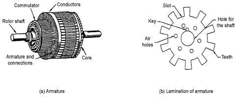
Figure 3.7 Armature of a DC Machine
3.4.5 Armature Windings
The armature windings, which are the first wound in the form of flat rectangular coils, are usually former wound. Finally, the armature coils are pulled into their appropriate shape in a coil puller. The various conductors of the coils are insulated from each other. The armature conductors are placed in armature slots. The armature conductors are held in the slots by wedges made of fibre, driven into the tops of the slots to avoid the flying of conductors under the centrifugal forces. Wood is not used to make the armature core because of its high reluctance and non-capability of bearing high rotational torque.
3.4.6 Commutator
A commutator is a mechanical device. It facilitates the collection of current from the armature conductors. Figure 3.8 shows the commutator made of a number of wedge-shaped segments or bars made of copper, which are assembled to form a cylinder. These segments are insulated from each other by thin layers of mica, and each commutator segment is connected to one end of coil. This insulation is designed to withstand voltage not less than 15 V The number of commutator segments is equal to the number of coils. The commutator along with the brush gear helps to convert the alternating current induced in armature conductors into unidirectional current across the brush.
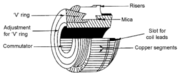
Figure 3.8 Commutator of a DC Machine
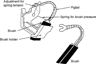
Figure 3.9 Pigtail Brush
3.4.7 brushes and bearings
The function of the brushes, which are housed in a brush holder, is to collect current from the commutator and to supply the same to the external circuit. The brushes are placed in such a way that they can rest on the commutator by placing them in the brush holder against the action of a spring. The tension of the spring can be adjusted. Figure 3.9 shows the pigtail brush with its holder.
The brushes are usually made of carbon or graphite and are in the shape of a rectangular block. The ball bearings are frequently employed for their reliability. Roller bearings are preferable for heavy duties. Table 3.1 summarizes the essential parts of a DC machine.
Table 3.1 Essential Parts of a DC Machine
| Part | Material Used |
| Yoke | Cast iron (small machine), cast steel (small large) |
| Field system | High-grade copper or aluminium enamelled wire or strip |
| Armature, core | Laminated sheet steel (0.4-0.6 mm) |
| Armature conductor | Super-enamelled copper wire or strip |
| Commutator | High-grade copper |
| Brush | Copper/carbon |
3.5 RING WINDINGS
These are not used in modern DC machines because these are the earliest forms of armature windings and these windings are very useful to understand the action of the commutator windings. Figure 3.10 shows the ring winding of a primitive DC generator where the core is usually made of steel laminations and insulated from each other. Figure 3.10 shows that the core has eight coils and each coil consists of two turns. Si and Fi represent the start and end of the coil ‘i’. The finish of the coil ‘i’ is connected to the start of the coil ‘i + l’ and so on until the finish of the last coil is connected to the start of the first coil. The commutator segment is connected to the junction between the neighbouring coils, that is, to the finish of one coil and the start of the another coil. The dotted lines in Figure 3.10 are the flux lines. An electromagnetic field is set up by the electromagnet. For the anticlockwise direction of rotation of the armature, the emf induced in the coils under the north poles will be directed away from the papers and that of in the coils under the south poles will be directed into the papers. Hence, the emfs of the coils under the north pole and the south pole are indicated by crosses and dots.
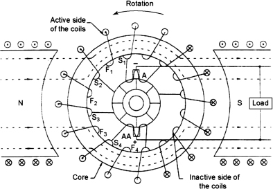
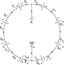
Figure 3.11 Equivalent Circuit of Figure 3.10
The equivalent circuit of Figure 3.10 is shown in Figure 3.11. The total emf induced around the closed loop will be zero.
But for the brush position shown in Figure 3.11, there will be two circuits. These two circuits are parallel between the brushes where each circuit contains equal number of coils generating emf acting from A to AA. Therefore, the current in each circuit will be half of the total current. The emf between the brushes A and AA depends on the emf/conductor as well as the number of conductors in each series circuit. If the brushes are placed such that one half of the coil comes under the north pole and the remaining half comes under the south pole, the maximum emf will be across the brushes. To achieve this, the brushes are to be placed one pole pitch apart, that is, 180 electrical degrees. The number of conductors generating emf should not vary due to the rotation of the armature, and in this case the voltage between the brushes A and AA will remain constant. The number of parallel paths in ring windings is equal to the number of poles, and hence two parallel paths exist in Figure 3.11. For six poles, the number of parallel paths will be six. The following are the disadvantages of ring windings:
- Each turn has to be taken around the core by the hand, and hence it is very expensive.
- Less than half of the windings are useful for generating the emf because a small portion of the winding is effective for cutting the flux.
- Commutation conditions are not good.
These windings are obsolete today, but they are very useful for better understanding of the working of the commutation. These windings are inferior to drum windings in respect of both mechanical and constructional points of view.
3.6 DRUM WINDINGS
The simplest form of drum winding is shown in Figure 3.12, where the armature carries single coil of many turns and the active sides are housed in two diametrically opposite slots.
For the normal slotted armature, the coil ends are placed in such a way to embrace the teeth, shown in Figure 3.13. The coil has two active coil sides. The active coil sides only cut the flux, whereas the inactive coil sides do not cut the flux. The coils in drum windings are placed in the slots of the armature on outer periphery.
To facilitate the satisfactory end connections, double-layer windings are used in DC windings. Multiturn coils of a DC machine are shown in Figure 3.14, where each single turn consists of two sides of the coil. The upper coil side is placed in the top layer of one slot, whereas the other coil side is placed in the bottom layer of another slot. These two coil sides are usually displaced by about a pole pitch, shown in Figure 3.15.
The coil span indicates the separation between the two sides of the same coil, and it is expressed in terms of armature slots. The coil span is usually one pole pitch. In practice, the number of turns is used to form a coil without joints. The change from the upper coil side to the lower coil side is done by means of bend, that is, kink, which is introduced at the back end of the coil shown in Figure 3.16.
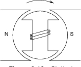
Figure 3.12 Slotted Armature with Coils
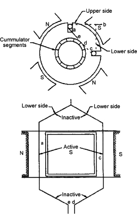
Figure 3.13 Drum-type Armature Coil
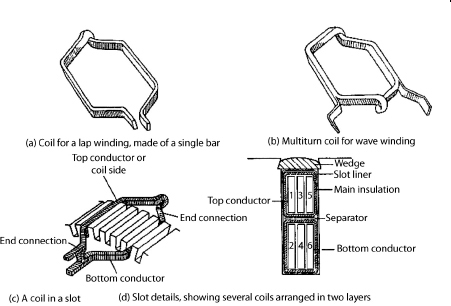
Figure 3.17 shows that in double-layer windings, each slot contains the upper side/sides of one or more coils along with the lower side/sides of a corresponding number of other coil side/sides of a coil separated by a coil. Figure 3.18 shows two-turn coil used in the drum winding.
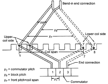
Figure 3.15 Two-layer Windings
Figure 3.17 shows the upper coil sides (a, b) of a coil in the upper portion of the slot. The bottom layer is occupied by the lower coil sides (8´, 9´) of some other coils (8, 9).
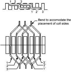
Figure 3.16 End Connections
3.6.1 Number of Coil Sides per Layer
The number of coil sides per layer is totally dependent on the number of coils and the number of slots. In each slot, there are an upper layer and a lower layer. If each slot contains one side per layer, the number of slots required is equal to the number of coils. Due to the limited number of available slots, it is not always possible to have two coil sides per slot. Hence, as many as four coil sides per layer become necessary. The arrangement of two coil sides per layer has been shown in Figure 3.16, where the upper coil sides of coils 1, 2 and 3 are denoted by 1, 2 and 3, respectively, and the lower coil sides by 1´, 2´ and 3´, respectively.
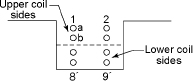
Figure 3.17 Arrangement of Conductor in a Slot with Two-coil Sides per Layer of a Two-turn Coil
3.6.2 Coil Span
The arrangement of coil sides in the slots has been shown in Figures 3.15 and 3.16. The separation of the upper coil side and the lower coil side of the same coil is expressed in terms of coil span, which is equal to the pole pitch for a full-pitched coil. Pole pitch is defined by the number of slots per pole. If the number of slots is 20 for a four-pole machine, the number of slots per pole![]() . For a full-pitched coil, the coil span in this case becomes 5. For a full-pitched coil, one coil side lies under the north pole, whereas the other coil side of the same coil lies under the south pole, and the emf induced in the two coil sides will be additive and the emf induced is maximum in this case. If the coil span becomes less than one pole pitch, one coil side lies under the north pole (say) and the other coil side of the same coil lies in the midway between the two coils and the emf induced between them will not be maximum. To provide good commutation, the coil span is made less than the pole pitch by a slot. For example, if the number of available slots is 23 for a four-pole machine, 23 the pole pitch becomes
. For a full-pitched coil, the coil span in this case becomes 5. For a full-pitched coil, one coil side lies under the north pole, whereas the other coil side of the same coil lies under the south pole, and the emf induced in the two coil sides will be additive and the emf induced is maximum in this case. If the coil span becomes less than one pole pitch, one coil side lies under the north pole (say) and the other coil side of the same coil lies in the midway between the two coils and the emf induced between them will not be maximum. To provide good commutation, the coil span is made less than the pole pitch by a slot. For example, if the number of available slots is 23 for a four-pole machine, 23 the pole pitch becomes ![]() . In this case, the coil span either 5 or 6 may be employed, which has no effect on the type of winding. If the coil span is not an integer, the integer value is considered.
. In this case, the coil span either 5 or 6 may be employed, which has no effect on the type of winding. If the coil span is not an integer, the integer value is considered.
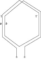
Figure 3.18 Two-turn Coil Winding
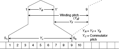
Figure 3.19 Winding Pitch, Commutator Pitch and Coil Span of a Coil Winding
3.6.3 Winding Pitch
In Figure 3.19, the finish of one coil is connected to the start of the next coil which is used for large machines. For small machines, Figure 3.19 shows that the finish of the first coil is connected to the start of the ninth coil, that is, two pole pitches apart. The displacement of the two consecutive coils is connected in series termed as pole pitch. In Figure 3.19, the winding pitch is equal to 8.
3.6.4 Commutator Pitch
The coil ends of a coil are connected to the commutator segments, and the displacement between the two commutator segments to which the two ends of a coil are joined is known as commutator pitch (Yc). The coil ends shown in Figure 3.19 are connected to the commutator segments 1 and 9. Therefore, the commutator pitch is 9 – 1 = 8. For the simple ring and lap winding, the commutator pitch is 1. The number of insulated pieces between the two ends of a coil is known as commutator pitch because consecutive commutator segments are insulated from each other. For lap and ring windings, the commutator pitch is unity.
3.6.5 Numbering of Armature Conductors
There are various methods to number the armature conductors. The easiest method is to number the coils instead to number the coil sides. From Figure 3.19, the upper coil side of coil 1 is denoted as 1 and the lower coil side of coil 1 is denoted as 1´. The junction of two different coil sides is joined to the commutator segments. The number of commutator segments is equal to the number of coils. From Figure 3.19, it is clear that the number of commutator pitch and winding pitch is equal. Therefore, in practice, it is enough to deal with the commutator pitch. The numbering of multiturn coil is shown in Figure 3.18, but the individual turn has not been shown.
3.6.6 Difference Between Coil Span and Winding Pitch
The winding pitch or commutator pitch has a vital role in deciding the type of winding, but the coil pitch has no influence on the type of winding. There will not be any alteration on the performance of the machine for any change in coil span, whereas a slight change in the winding pitch can produce a considerable effect on the performance of the machine.
3.7 TYPES OF DC WINDINGS
The following are the classifications of DC windings depending on the connection of their coil ends:
- lap winding and
- wave winding.
Figure 3.20(a) shows a simple coil. Figure 3.20(b) shows a simple lap winding where the two ends of the coil are taken to the adjacent commutator segments and the coil ends are bent inwards. Figure 3.20(c) shows a simple wave winding where the two ends of the coil are taken to the commutator segments separated by a distance apart and the coil ends are bent outwards. The following definitions are very useful:
- Pole pitch: It is defined as the number of armature conductors per pole. If there are 60 conductors and 6 poles, the pole pitch is 60/6 = 10.
- Conductor: It is defined as the length of a wire lying in the magnetic field, shown in Figure 3.20(a).
- Coil: Two conductors with their end connections, shown in Figure 3.20(a), form one coil. The coil may be single-turn coil or multiturn coil. The end connections are called overhang.
- Coil pitch (Ys): It is defined as the distance between two sides of a coil in terms of armature slots. In other words, it is defined as the periphery of the armature between two sides of a coil. If the coil pitch is equal to the pole pitch, the winding is said to be full pitched. Otherwise, it is a fractional pitch.
- Front pitch: It is defined as the distance between the second conductor of one coil and the first conductor of the next coil, shown in Figure 3.20(b).
- Back pitch: It is defined as the distance measured in terms of armature conductors that a coil advances on the back of the armature, shown in Fig. 3.20(b).
- Resultant pitch (YR): It is defined as the distance between the beginning of one coil and the beginning of the next coil. For the lap winding, YR = YB - YF, and for wave winding, YR = YF + YB.
- Coil pitch (Yc): It is defined as the distance between the beginning of one coil and the beginning of next coil, shown in Figures 3.20(b) and 3.20(c) for lap and wave windings, respectively.
3.7.1 Simple Lap Winding
The lap winding as well as the wave winding is most commonly used for drum-type armatures. To get these types windings, the following rules are commonly used:
- The windings must be full pitched; that is, the front and back pitch must be approximately equal to the pole pitch.
- To place the coils properly on the armatures, the front pitch as well as the back pitch must be odd.
- The commutator segments are the images of the coil; that is, the number of commutator segments is equal to the number of the coils.
- The windings must close upon itself.
The lap winding has been shown in Figure 3.20(a). The following points are important for the simple lap winding: - The back pitch (YB) and the front pitch (YF) are odd and opposite signs. They differ by two or some multiples thereof.
- YB and YF must be nearly equal to the pole pitch.
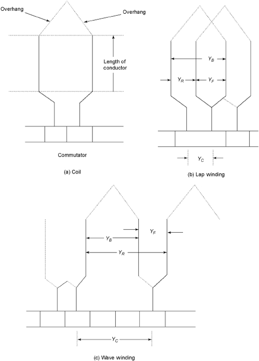
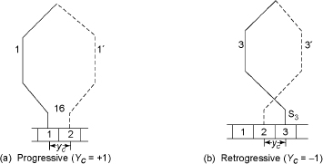
Figure 3.21 Simple Lap Winding
- The average pitch
 is equal to the pole pitch.
 - The resultant pitch is the arithmetical difference between YB and YF.
- The commutator pitch YC = ±1.
- The number of slots for a two-layer winding as well as the commutator segments is equal to the number of coils.
- The number of parallel paths in the armature = mP, where m is the multiplicity of the winding and P is the number of parallel paths.
For the progressive or right-handed winding,  and
and ![]() and for the retrogressive or left- handed winding,
and for the retrogressive or left- handed winding, ![]() and
and ![]() .
.
Similarity between the lap winding and the ring winding are there except the way they are placed in the armature. In ring winding, the finish of the coil is connected to the start of the next coil and so on, and hence the winding pitch or commutator pitch is always unity. A simple lap winding can be progressive or retrogressive, shown in Figures 3.21(a) and 3.21(b), respectively.
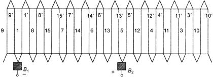
In the progressive winding, the coil ends are connected to the commutator segments in the ascending order, whereas in the retrogressive winding, these are connected to the commutator segments in the descending order. Therefore, for the simple lap winding, Yc = ±1, where ‘+’ is for the progressive winding and ‘-’ is for the retrogressive winding. Figure 3.22 shows the developed view of the simple lap winding having four poles and 16 slots, with two coil sides per slot using single-turn coils only. Since there are two coil sides per slot, the number of coils required is 16. The winding is drawn in a progressive way (Yc = +1), and the coil assumed here is full pitched. The upper coil sides are denoted by 1, 2, 3, etc., whereas the lower coil sides are denoted by 1´, 2´, 3´, etc. The pole pitch for this arrangement ![]() . The coil span taken here is four slots/pole, that is, full pitched. The solid line shows the upper coil sides, whereas the dotted lines show the lower coil sides. The upper coil side of coil 1, that is, 1 (thick line), is connected to commutator segment 1. The lower coil side of coil 1, that is, 1´ (dotted line), will be placed in 1 + 4, that is, 5th slot. The front portion of coil side 1´ (shown by dotted line) is connected to commutator segment 2. The upper coil side 2, that is, 2 (shown by thick line), is connected to commutator 2, and the lower coil side of coil 2, that is, 2´, will be placed in 2 + 4, that is, 6th slot. The front portion of coil side 2´ (shown by dotted line) is connected to commutator segment 3. In the similar way, the winding diagram is completed. The upper coil side of coil 13, that is, 13 (shown by thick line), is connected to commutator segment 13, and the lower coil side of coil 13, that is, 13´, will be placed in 13 + 4, that is, 17th slot. The available of number of slots is 16. Therefore, 17th slot = 17 - 16, that is, 1st slot. The remaining diagram can be completed in a similar way.
. The coil span taken here is four slots/pole, that is, full pitched. The solid line shows the upper coil sides, whereas the dotted lines show the lower coil sides. The upper coil side of coil 1, that is, 1 (thick line), is connected to commutator segment 1. The lower coil side of coil 1, that is, 1´ (dotted line), will be placed in 1 + 4, that is, 5th slot. The front portion of coil side 1´ (shown by dotted line) is connected to commutator segment 2. The upper coil side 2, that is, 2 (shown by thick line), is connected to commutator 2, and the lower coil side of coil 2, that is, 2´, will be placed in 2 + 4, that is, 6th slot. The front portion of coil side 2´ (shown by dotted line) is connected to commutator segment 3. In the similar way, the winding diagram is completed. The upper coil side of coil 13, that is, 13 (shown by thick line), is connected to commutator segment 13, and the lower coil side of coil 13, that is, 13´, will be placed in 13 + 4, that is, 17th slot. The available of number of slots is 16. Therefore, 17th slot = 17 - 16, that is, 1st slot. The remaining diagram can be completed in a similar way.
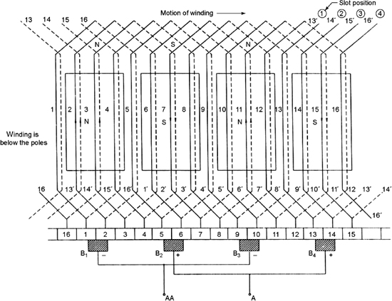
Figure 3.22 Developed View of Simple Lap Winding
To represent the poles in Figure 3.22, they must be placed equally spaced. The width of the pole is taken as ![]() times the pole pitch, that is,
times the pole pitch, that is, ![]() slots.
slots.
In Figure 3.22, it is assumed that the winding is progressive, that is, right handed, and the winding is behind the poles. The right hand rule is used to mark the emf on the windings. The emf induced in the conductors will be away from the commutator. The number of parallel paths in the lap winding is equal to the number of poles. The number of conductors per series (Zc) will be the total number of conductors (Z)/number of poles (P). Since two conductors make a turn, the total number of turns = Z/2.
The number of brushes for the lap winding is equal to the number of poles. The brushes must be equally spaced around the commutator, and there will be no emf induced to the coil ends across which the brushes are placed. The conductor 1 is moving in the interpolar space and the emf is induced in it. The ends of coils are connected to segments 1 and 2 of the commutator. Brush B1 is placed across segments 1 and 2 of the commutator. The remaining brushes B2, B3 and B4 are displaced one pole pitch apart from each other. Brush B2 is placed across segments 5 and 6. Brush B3 is placed across segments 9 and 10. Brush B4 is placed across segments 13 and 14. The direction of emf in conductor 2 is away from the commutator. Therefore, brush B1 is marked as negative. The emf induced in conductor 6 is towards the commutator and hence the brush B2 is marked as positive. Similarly, the polarity of brushes B3 and B4 will be negative and positive, respectively. The number of parallel paths between A and AA will be 4. To determine the number of conductors per parallel path, let us start from terminal A connected to brushes B2 and B4. It is possible to proceed either from B2 or from B4. If starting is carried out from B2, the tracing is done using the commutator segment 5 or 6. Segment 6 is connected to the coil ends 6 and 5´. The tracing using segment 6 is shown as follows:
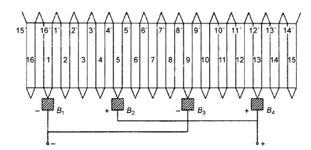
Figure 3.23 Sequence Diagram of Figure 3.22
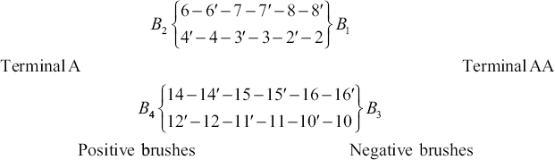
Figure 3.23 shows the sequence diagram, which indicates the sequence of connection of coils.
The coils 1-1´, 5-5´, 9-9´ and 13-13´ do not appear in the parallel path because they are momentarily short circuited by brushes B1, B2, B3 and B4, respectively.
3.7.2 Wave Winding
Figure 3.20(c) shows the wave winding. For the wave winding the following points are important:
- YB and YF are odd and the same sign.
- YB and YF are near equal to the pole pitch and differ by 2.
- The resultant pitch (YR) is the sum of YB and YF
- The commutator pitch (YC) =
- The average pitch (YA) is an integer and given by YA=
- The number of coils (NC) can be obtained from NC =

- The number of parallel path = 2m, where m is the multiplicity of the winding.
For the lap winding all the pole groups of coils generating emf in the same direction at any instant of time are connected in parallel by the brushes. In case of the wave winding, all the coils carrying current in the same direction are connected in series. Therefore, the coils carrying current in a particular direction are connected in one series circuit, whereas the coils carrying current in the other particular direction are connected in another series circuit. Hence, there are two parallel circuits in wave windings.
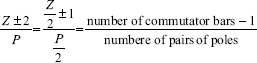
Figure 3.24 shows the principle of wave windings, where coils 1, 2 and 3 are situated two pole pitches apart. The dotted lines of the front connections are for the lap winding in which each coil is connected across a pair of adjacent commutator segments. These coils are placed symmetrically with respect to the poles. Therefore, the emf generated in the three coils will be identical in direction. These three coils are connected in series as a group. The ends of the groups are joined to the adjacent commutator segments. The coil ends are bent outwards and this has been shown by the arrow. The coil ends are connected to the commutator segments which are two pole pitches apart. The finish of coil 1 (F1) is connected to the start of coil 2 (S2). The finish of coil 2 (F2) is connected to the start of coil 3 (S3). The finish of coil 3 (F3) is connected to the commutator segment which is adjacent to the commutator segment at which the start of coil 1(S1) is connected. From junction points of the coils, the connection of the commutator is taken. The commutator pitch (Yc) is the number of commutator segments between S1 and F1. In Figure 3.24, there are three pairs of poles, and if C be the total number of commutator segments, then we have the following:
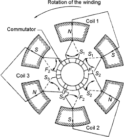
Figure 3.24 Principle of Wave Winding
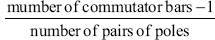
The number of coils joined in series is equal to the number of pairs of poles. The relation between the commutator segments or the number of coils and the commutator pitch for a machine having ‘p’ pairs of poles is expressed as follows:
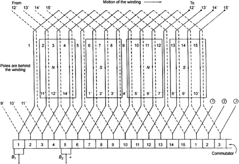
Figure 3.25 Simple Wave Winding with Four Poles
In Equation (3.2),‘+’ sign is for the progressive winding whereas the ‘-’ sign is for the retrogressive winding.
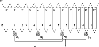
Figure 3.25 shows the simple wave winding with four poles and an armature having 15 slots and single-turns coils wound with two conductors per slot. Here, C = number of coils = number of commutator segments = 15.
For the retrogressive winding, the commutator pitch is given by ![]() and the pole pitch =
and the pole pitch =![]() . Therefore, the coil span is taken as 3 or 4. The coil span of 4 near to the pole pitch is taken. The numbering of conductor similar to the lap winding is taken. The upper coil sides are marked as 1, 2, 3, etc., whereas the lower coil side is marked as 1´, 2´, 3´, etc. Let the upper coil side of coil 1 (shown by thick line) be placed in slot 1. The lower coil side of coil 1, that is, 1´, is placed in the slot 1 + 4, that is, 5th slot. The other end of coil 1´ is connected to the start of 1 + 7, that is, 8th coil that is separated from coil side 1 by a commutator pitch Yc = 7. The junction of 1´ and 8 is connected to segment 8 of the commutator. The lower coil side of coil 8, that is, 8´, will be placed in 8 + 4, that is, 12 slots. The lower coil side of coil 8, that is, 8´, will be connected to the start of coil side 8 + 7, that is, 15. This procedure is repeated to obtain Figure 3.25. In Figure 3.25, it is assumed that the poles are behind the coils and the poles are equally spaced. For the left to the right motion of the winding, the direction of emf induced in the conductors situated above the north pole will be towards the commutator whereas the direction of emf induced in the conductors situated below the south pole will be away from the commutator.
. Therefore, the coil span is taken as 3 or 4. The coil span of 4 near to the pole pitch is taken. The numbering of conductor similar to the lap winding is taken. The upper coil sides are marked as 1, 2, 3, etc., whereas the lower coil side is marked as 1´, 2´, 3´, etc. Let the upper coil side of coil 1 (shown by thick line) be placed in slot 1. The lower coil side of coil 1, that is, 1´, is placed in the slot 1 + 4, that is, 5th slot. The other end of coil 1´ is connected to the start of 1 + 7, that is, 8th coil that is separated from coil side 1 by a commutator pitch Yc = 7. The junction of 1´ and 8 is connected to segment 8 of the commutator. The lower coil side of coil 8, that is, 8´, will be placed in 8 + 4, that is, 12 slots. The lower coil side of coil 8, that is, 8´, will be connected to the start of coil side 8 + 7, that is, 15. This procedure is repeated to obtain Figure 3.25. In Figure 3.25, it is assumed that the poles are behind the coils and the poles are equally spaced. For the left to the right motion of the winding, the direction of emf induced in the conductors situated above the north pole will be towards the commutator whereas the direction of emf induced in the conductors situated below the south pole will be away from the commutator.
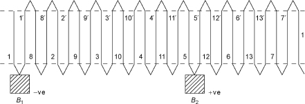
Here, the conductor is taken in which the emf is induced and brush B1 is placed below the commutator segment 1. The other brush is placed with a separation of the coil span, that is, 1 + 4 = 5, that is, under segment 5. The polarity of brush B1 is taken as positive because the emf induced in conductor 15 is towards the commutator, whereas the polarity of brush B2 is taken as negative because the emf induced in conductor 6 is away from the commutator. One parallel path is from brush B2 through 5–5´–12–12´... up to brush B1 and the other parallel path starting from B2 through 13´–13–6´–6… up to brush B1. These two parallel circuits can be represented as follows:
Positive brush B1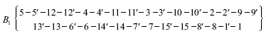 Negative brush B2
Figure 3.26 shows the sequence diagram. Only two brushes are essential in the wave winding.
Example 3.1 Draw the developed view of a simple lap winding of four-pole DC generators having 12 slots with two coil sides per slot.
Solution
![]()
The coil span taken here is equal to the full pole pitch of four slops/pole. It is assumed here that the winding is moving from left to right and the winding is behind the poles. Using a full-pitched coil span, the winding is drawing in the progressive way (Yc = +1). The upper sides of the coil are denoted as 1, 2, 3, etc., and the lower sides of the same coil are denoted as 1´, 2´, 3´, etc. Table E3.1 shows the sequence of back connection and front connection.
Table E3.1 Sequence of back connection and front connection of Example 3.1
| Back Connection | Front Connection |
| 1 is connected to 1´ (4) | 1´ is connected to 2 (2) |
| 2 is connected to 2´ (5) | 2´ is connected to 3 (3) |
| 3 is connected to 3´ (6) | 3´ is connected to 4 (4) |
| 4 is connected to 4´ (7) | 4´ is connected to 5 (5) |
| 5 is connected to 5´ (8) | 5´ is connected to 6 (6) |
| 6 is connected to 6´ (9) | 6´ is connected to 7 (7) |
| 7 is connected to 7´ (10) | 7´ is connected to 8 (8) |
| 8 is connected to 8´ (11) | 8´ is connected to 9 (9) |
| 9 is connected to 9´ (12) | 9´ is connected to 10 (10) |
| 10 is connected to 10´ (13, i.e. 13 - 12 = 1) | 10´ is connected to 11 (11) |
| 11 is connected to 11´ (14, i.e. 14 - 12 = 2) | 11´ is connected to 12 (12) |
| 12 is connected to 12´ (15, i.e. 15 - 12 = 3) | 12´ is connected to 1 (1) |
The numbers in brackets indicates the slots.
Figure E3.1 shows the sequence diagram.
Example 3.2 Draw a developed view for a two-layer, wave-winding, four-pole DC generator having 13 slops with two coil sides per slot.
Solution
![]()
Therefore, the span taken here is 4. The commutator pitch Yc can be computed by using the progressive winding as follows:
![]()
Similar assumptions in Example 3.1 are also done here. Table E3.2 shows the sequence of back connection and front connection.
Table E3.2 Sequence of back connection and front connection of Example 3.2
| Back Connection | Front Connection |
| 1 is connected to 1´ | 1´ is connected to 1 + 7 (i.e. 8) |
| 8 is connected to 8´ | 8´ is connected to 8 + 7 (i.e. 15 - 13 = 2) |
| 2 is connected to 2´ | 2´ is connected to 2 + 7 = 9 |
| 9 is connected to 9´ | 9´ is connected to 9 + 7 = 16 (i.e. 16 - 13 = 3) |
| 3 is connected to 3´ | 3´ is connected to 3 + 7 = 10 |
| 10 is connected to 10´ | 10´ is connected to 10 + 7 = 17 (i.e. 17 - 13 = 4) |
| 4 is connected to 4´ | 4´ is connected to 4 + 7 = 11 |
| 11 is connected to 11 ´ | 11´ is connected to 11 + 7 = 18 (i.e. 18 - 13 = 5) |
| 5 is connected to 5´ | 5´ is connected to 5 + 7 = 12 |
| 12 is connected to 12´ | 12´ is connected to 12 + 7 = 19 (i.e. 19 - 13 = 6) |
| 6 is connected to 6´ | 6´ is connected to 6 + 7 = 13 |
| 13 is connected to 13´ | 13´ is connected to 13 + 7 = 20 (i.e. 20 - 13 = 7) |
| 7 is connected to 7´ | 7´ is connected to 7 + 7 = 14 (i.e. 14 -13 = 1) |
Figure E3.2 shows the sequence diagram.
3.8 EQUALIZING CONNECTIONS FOR LAP WINDING
In a simple lap winding, shown in Figure 3.27, the emfs generated by all the pole groups of coils are in the same direction at any instant and they are connected in parallel by the brushes. If the emfs generated in each parallel circuit are not equal, this results in circulating currents among the parallel paths even at no-load condition. This causes unnecessary power loss and overheating of the windings. To divert these circulating currents, equalizing connections are used. Using a total number of slots divisible by the number of poles, the magnitude of the circulating currents in lap windings can be minimized and hence inequalities in the emfs in the parallel paths can be minimized. Using equalizing connection, the above can be satisfied. In Figure 3.27, the numbers of parallel paths and the conductors in each parallel path are distributed under adjoining poles. Any difference in the reluctance of the magnetic circuit due to unequal air gaps etc. results inequality in the flux per pole. Hence, the emf generated in each circuit will be different.
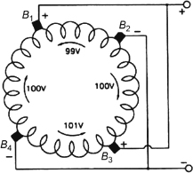
Figure 3.27 Lap-wound Armature
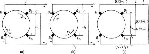
Figure 3.28 Circulating Currents in Brush Connections
The generated emfs and their direction are assumed and shown in Figure 3.27. In the parallel circuits B1B2B3 and B1B4B3, the resultant emf is 1 V, shown in Figure 3.28(a). The circulating current in the conductor bridging brushes B1 and B3 is I1, shown in Figure 3.28(a). Similarly, the resulting voltage acting in the parallel circuits B4B1B2 and B4B3B2 is also 1 V, shown in Figure 3.28(b).
The circulating current I1 flows through the conductor joining brushes B2 and B4, shown in Figure 3.28(b).
If the emfs generated in each parallel path are equal, the current per branch becomes 1/2 for the load current I delivered by the generator. The resultant current at brushes B1 and B2 will be ![]() due to the presence of circulating current I1 and that of at brushes B3 and B4 will be
due to the presence of circulating current I1 and that of at brushes B3 and B4 will be ![]() . Therefore, brushes B3and B4 will be overloaded and it results in excessive sparking.
. Therefore, brushes B3and B4 will be overloaded and it results in excessive sparking.
Figure 3.29 shows the equalizing connections between R-R´, S-S´ and T-T´ to minimize or even avoid the sparking. For non-uniform potential of the above points, the current I1 will flow through R-R´ instead of through the brushes. In practice, the number of equalizing connections employed varies between 6 and 12 which are arranged in the form of a ring to get the proper arrangement of connections at all positions of the armature to divert the currents. For the number of poles more than two, the numbers of parallel paths are more in the lap winding compared to the wave winding. Table 3.2 shows the comparison between lap winding and wave winding.
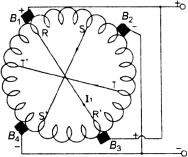
Figure 3.29 Equalizing Connections
Table 3.2 Comparison Between Lap Winding and Wave Winding
| Lap Winding | Wave Winding |
|
|
3.9 USES OF LAP AND WAVE WINDINGS
Wave windings give more emf for a given number of pole and armature conductors, whereas lap windings give the same emf for more number of conductors. Hence, the winding cost increases for the lap winding. Equalizing connections are not required in the wave winding, but this is mandatory for the lap winding. In the lap winding, there are P parallel paths when the numbers of poles are P, whereas in the wave winding, the numbers of parallel paths are two. Therefore, any inequality of pole fluxes in the wave winding cannot produce unequal voltages because this inequality of fluxes affects the two paths equally. In the lap winding, the inequality of fluxes produces unequal voltages and causes sparking at the brushes.
3.10 DUMMY COILS
These coils are used in the wave winding when the requirement of windings is not satisfied by armature punching. Since these coils are not connected to the commutator, they do not affect the electrical characteristic of the windings.
3.11 PRINCIPLE OF DC GENERATOR
Figure 3.30 shows a single-turn generator. The coil is rotated in the anticlockwise direction with the help of the prime mover. During its rotation, the conductors ab and cd cut the lines of flux. According to Faraday's law of electromagnetic induction, emf is induced in the conductors, which drives the current through the conductor. The conductors are connected to brushes through the slip rings. The magnitude of induced emf depends on the position of the coil in the magnetic field. Figure 3.31 shows the different instants of the induced emf due to different positions of the coil. The magnetic field is produced either by a permanent magnet or by an electromagnet energized by the DC supply.
When the angle θ = 0°, the coil is perpendicular to the magnetic field and the instantaneous component of velocity of conductors ab and cd is parallel to the magnetic field. The flux linked with the coil is maximum, but the rate of change of flux is minimum. Hence, emf cannot be generated. Therefore, no current flows through the conductors.
When 0° < θ < 90° due to rotation of the coil in the anticlockwise direction, the velocity of the conductors has two components, that is, v sinθ and v cosθ. Therefore, the conductors will cut the flux due to v sinθ. Hence, emf is induced in the conductors and the current flows in the conductors.
When the angle θ = 90°, the coil is parallel to the magnetic field and the instantaneous component of velocity of conductors ab and cd is perpendicular to the magnetic field. The flux linked with the coil is minimum, but the rate of change of flux is maximum. Hence, emf generated is maximum. Therefore, the maximum current flows through the conductors.
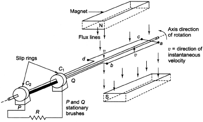
Figure 3.30 Single-turn Generator
When the coil rotates from θ = 90° to θ = 180°, the component of velocity, that is, v sinθ of conductors perpendicular to the field, decreases and hence emf is induced in the conductors and the current flow in the conductors decreases.
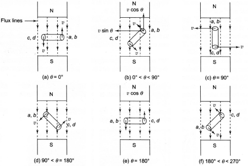
Figure 3.31 Induced emf for Different Instants
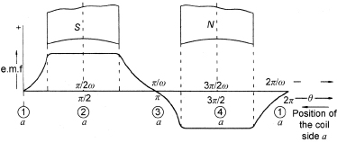
Figure 3.32 Graphical Representation of Generated Current
When the angle θ = 180°, the coil is perpendicular to the magnetic field and the instantaneous component of velocity of conductors ab and cd is parallel to the magnetic field. The flux linked with the coil is maximum, but the rate of change of flux is minimum. Hence, emf cannot be generated. Therefore, no current flows through the conductors.
When 180° < θ < 270° due to rotation of the coil in the anticlockwise direction, the velocity of the conductors has two components, that is, v sinθ and v cosθ in the direction opposite to the case of 0° < θ < 90°. Therefore, the conductors cut the flux due to v sinθ. Hence, emf is induced in the conductors in the direction opposite to the case of 0° < θ < 90° and current flows in the conductors in the direction opposite to the case of 0° < θ < 90°.
When the angle θ = 270°, the coil is parallel to the magnetic field and the instantaneous component of velocity of conductors ab and cd is perpendicular to the magnetic field. The flux linked with the coil is minimum, but the rate of change of flux is maximum. Hence, emf generated is maximum in the direction opposite to the case of θ = 90°. Therefore, the maximum current flows through the conductors in the direction opposite to the case of θ = 90°.
When the coil rotates from θ = 270° to θ = 360°, the component of the velocity, that is, v sinθ of conductors perpendicular to the field, decreases and hence emf is induced in the conductors and the current flow in the conductors decreases.
When the angle θ = 360°, the coil is perpendicular to the magnetic field and the instantaneous component of velocity of conductors ab and cd is parallel to the magnetic field. The flux linked with the coil is maximum, but the rate of change of flux is minimum. Hence, emf cannot be generated. Therefore, no current flows through the conductors.
The direction of flow of current through the conductors can be found by Fleming’s right-hand rule.
Figure 3.32 shows the graphical representation of generated current.
3.12 OPERATION OF A SIMPLE DC GENERATOR WITH A TWO-SEGMENT COMMUTATOR
Figure 3.33 shows a two-pole DC generator with a single coil to explain working of a simple DC generator with a two-segment commutator. The two ends of the coil (conductor a and conductor b) are brought out to split rings C1 and C2, respectively, which are made of copper. This split ring is termed as the commutator, and segments of the split ring are insulated from each other. This arrangement is different from the arrangement shown in Figure 3.30.
The split rings are rigidly fixed to the axis of rotation so that the rotation of the coil ensures the rotation of the segments C1and C2 of the commutator. Brushes B1 and B2 remain stationary and will come into contact alternately with C1 and C2 when the coil completes one revolution. The angle between the plane of the coil and the vertical axis is represented by θ. For the vertical position of the coil, that is, θ = 0, the soil side ‘a’ is at the position ‘1’ and the emf induced in the coil will be zero. Figure 3.34(a) shows this position. Brushes B1 and B2 bridge the commutator segments C1 and C2, and the coil becomes short circuited. The emf induced in coil sides ‘a’ and ‘b’ will be zero and the emf induced in brush B1 will be zero, as shown in Figure 3.35(a). The corresponding position of commutator segments has been shown in Figure 3.35(b) .
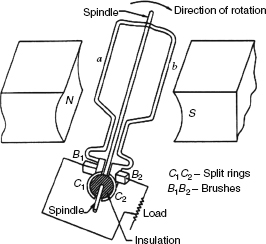
Figure 3.33 DC Generator with Two segment Commutator
For rotation of the coil through an angle ![]() , coil side ‘a’ occupies the position ‘2’ and it is under the south pole, as shown in Figure 3.34(b). The segment C1 comes into contact brush B1in this case. The magnitude of induced emf acts away from the paper, and it is represented by the dot which is taken as positive. Therefore, the polarity of the voltage of brush B1 will also be positive because coil side ‘a’ is connected to B1 through the commutator segment C1. Figure 3.35(a) shows the magnitude of the voltage, while Figure 3.35(b) shows the corresponding positions of the commutator segments with respect to the brushes. Coil side ‘a’ occupies position ‘3’ for further rotation of an angle
, coil side ‘a’ occupies the position ‘2’ and it is under the south pole, as shown in Figure 3.34(b). The segment C1 comes into contact brush B1in this case. The magnitude of induced emf acts away from the paper, and it is represented by the dot which is taken as positive. Therefore, the polarity of the voltage of brush B1 will also be positive because coil side ‘a’ is connected to B1 through the commutator segment C1. Figure 3.35(a) shows the magnitude of the voltage, while Figure 3.35(b) shows the corresponding positions of the commutator segments with respect to the brushes. Coil side ‘a’ occupies position ‘3’ for further rotation of an angle ![]() , that is, θ = π. Figure 3.34(c) shows the positions of the commutator segments C1 and C2. The position of the commutator segments C1 and C2 has been interchanged in this case. The emf induced in coil sides ‘a’ and ‘b’ will be zero and the emf induced in brush B1will be zero, as shown in Figure 3.35(a), and the corresponding position of commutator segments has been shown in Figure 3.35(b). For another rotation of the coil by an angle
, that is, θ = π. Figure 3.34(c) shows the positions of the commutator segments C1 and C2. The position of the commutator segments C1 and C2 has been interchanged in this case. The emf induced in coil sides ‘a’ and ‘b’ will be zero and the emf induced in brush B1will be zero, as shown in Figure 3.35(a), and the corresponding position of commutator segments has been shown in Figure 3.35(b). For another rotation of the coil by an angle ![]() , that is,
, that is, ![]() , coil side ‘a’ comes to the position ‘4’, which is under the influence of the north pole as shown in Figure 3.34(d). The magnitude of the induced emf will be maximum and is in the reversed direction shown by the cross. It acts on the paper. The segment C2 in this case is in contact with brush B1, which is connected to coil side ‘b’. Coil side ‘b’ is under the influence of the south pole and its induced emf is represented by dots. Therefore, the polarity of the voltage brush B1 in this case will remain positive, shown in Figure 3.35(a), and the corresponding position of commutator segments has been shown in Figure 3.35(b).
, coil side ‘a’ comes to the position ‘4’, which is under the influence of the north pole as shown in Figure 3.34(d). The magnitude of the induced emf will be maximum and is in the reversed direction shown by the cross. It acts on the paper. The segment C2 in this case is in contact with brush B1, which is connected to coil side ‘b’. Coil side ‘b’ is under the influence of the south pole and its induced emf is represented by dots. Therefore, the polarity of the voltage brush B1 in this case will remain positive, shown in Figure 3.35(a), and the corresponding position of commutator segments has been shown in Figure 3.35(b).
The polarity of brush B1 in this case becomes positive because it is always under the influence of the south pole in the case shown in Figure 3.35(b). For positions ‘2’ and ‘3’ of Figure 3.35(b), brush B1 is in contact with C1 and C2, which are connected to coil sides ‘a’ and ‘b’, respectively. In these two positions, coil sides ‘a’ and ‘b’ are under the influence of the south pole and the emf induced in them is away from the paper and hence positive. Therefore, the emf induced in brush Bl remains positive in these cases.
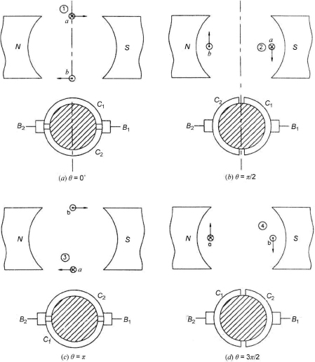
Figure 3.34 Relative Position of the Commutator Segments with Respect to the Brushes
Figure 3.36 shows a DC generator having a single-layer winding with more number of coils. Figure 3.37 shows the waveform of the voltage of brush B1, and the voltage waveform of each of the coils is displaced by a slot pitch angle (γ), shown in Figure 3.37. For the clockwise direction of rotation of the armature, the voltage induced in the coil ‘a2’ leads the voltage induced in the coil ‘a1’ by an angle γ. If the number of slots and the number of armature conductors are increased, the shape of the waveform can be improved.
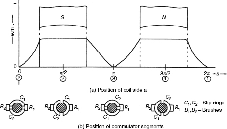
Figure 3.35 Waveform of the emf Generated at Brush B1
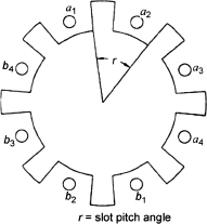
Figure 3.36 Slotted Armature with Four Coils
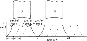
Figure 3.37 Waveforms of the Generated emf at Brush B1 (Armature Carries Four Coils)
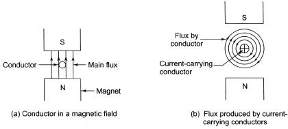
Figure 3.38 Flux due to Field and Conductor
3.13 PRINCIPLE OF DC MOTOR
The basic principle of operation of a DC motor is that a current-carrying conductor, if placed in a magnetic field, experiences a mechanical force. Figure 3.38(a) shows a conductor placed in a magnetic field produced by the field windings of a DC motor carrying current. The flux produced by the field windings is known as the main flux. Figure 3.38(b) shows the flux produced by the conductor alone. There are two fluxes present in the magnetic field. One is produced by the permanent magnet called the main flux and the other is produced by the current-carrying conductor. On the left side of the conductor, the two fluxes are additive in nature, whereas on the right side of the conductor, the fluxes are subtractive in nature. Therefore, the density of flux lines is stronger on the left side whereas it is weaker on the right side. This is shown in Figure 3.39. The flux distribution around the conductor acts like a stretched rubber band under tension and exerts a mechanical force on the conductor, which acts from left to right, shown in Figure 3.40.
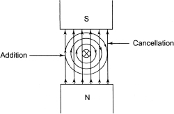
Figure 3.39 Interaction of Two Fluxes
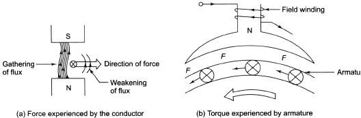
Figure 3.40 Force and Torque Experienced by Armature
The direction of rotation of the conductor can be found by Fleming’s left-hand rule.
3.14 CONSTRUCTION OF SYNCHRONOUS MACHINES
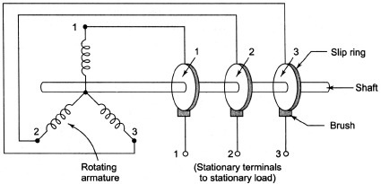
The principle of operation which depends on the principle of electromagnetic induction of a synchronous generator and DC motor is the same. According to the principle of electromagnetic induction, emf is induced in the conductors due to the rate of change of flux linkage, which is produced due to the relative motion between the conductors and the magnetic field. The magnetic field is on the stator, and the armature which carries the conductors is on the rotor in DC generators. On the other hand, the field winding is on the rotor and armature conductors is on the stator in synchronous generators. This is the main difference between DC generators and synchronous generators. But in both cases, the generated emf is alternating in nature. In DC generators, the induced emf depends on the total flux per pole and it is independent on the nature of flux distribution in space. On the other hand, the flux distribution in an alternator must be as nearly a sine wave as possible so that the maximum sinusoidal emf from a given value of the flux/pole is obtained. In DC generators, the commutator plays the role of production of unidirectional emf across the brush axis. In synchronous generators there is no need to use the commutator.
In case of the alternator, the following possibilities exist:
- rotating armature and stationary field or
- rotating field and stationary armature.
In practice, most of the alternators have rotating field-type construction with the stationary armature due to the following reasons:
- The generation level of AC voltage may be in the range of 11 kV to 33 kV, which gets induced in the armature. It is possible to provide large space to accommodate many conductors and insulation for the stationary armature. The ventilation arrangement for high-voltage side can be improved.
- Keeping high-voltage armature stationary, it is possible to avoid interaction of mechanical stress.
- It is very easy to collect high currents at high voltages from the stationary member.
Figure 3.41 Collection of Induced emf from Armature
- Since field coil needs very low voltage, it can easily be supplied with the help of the slip ring and brush assembly. At low voltage, it is possible to avoid sparking at the slip rings.
- Since the low-voltage level is on the field side, insulation cost is reduced. Field has low inertia. It is always preferable to keep a low inertia system as the rotating member because it is easy to rotate the low inertia system. It can also be rotated at high speed.
- Overall construction is simplified with rotating field and hence high output can be obtained.
- Only two slip rings are required to excite the field by DC supply.
- Cooling arrangement becomes very easy.
Synchronous generators export AC power to a bus bar, whereas synchronous motors import AC power from the source. The frequency of generated emf in a synchronous generator depends on the speed of the rotor. If the frequency of the generated emf of the synchronous generator is equal to the frequency of the bus bar, then it is possible to connect it to the bus bar provided other conditions are satisfied. (For detailed procedure, refer to Chapter 6.)
The main parts of synchronous machines are (i) the stator (armature) and (ii) the rotor (field).
3.14.1 Stator
Figure 3.42 shows the stator and the rotor of an alternator. The stator shown in Figure 3.43 consists of a core and slots to hold the armature winding like the armature of a DC generator, which is a stationary member of the alternator. The stator core is laminated to reduce eddy current loss and is made of steel stampings insulated from each other with varnish or paper, and ducts are provided through them for ventilating purposes. The ventilating ducts have been shown in Figure 3.44. To reduce hysteresis loss, the selected material for the core, which is a special steel alloy, must have small hysteresis loop. In small machines, the laminations are generally stamped out in complete rings. The entire core is fabricated in a frame made of cast iron to house the armature conductors. The frame only supports the core and does not carry any flux. In modern machines, the fabrication of stator frames is done from mild steel, which are welded together. There are two kinds of ventilations: natural ventilation and closed circuit ventilation. In natural ventilation, a fan is attached to both ends of the machine and atmospheric air is the ventilating medium. Since atmospheric air may contain injurious elements, such as dust, moisture and acidic fumes, which are harmful for the insulation of the winding, the closed circuit system is preferred for ventilation and hydrogen is used here as a ventilating medium.
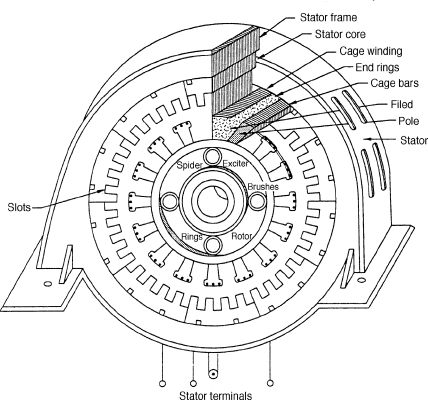
Figure 3.42 Stator and Rotor of an Alternator
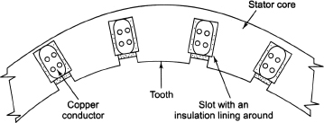
Figure 3.43 Stator
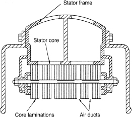
Figure 3.44 Ventilating Ducts
3.14.2 Rotor
Synchronous machine has different geometric structure of the rotor and hence it is classified as
- salient pole-type (P > 4, low speed) and
- smooth cylindrical pole-type (P < 4, high speeds).
3.14.2.1 Salient Pole-type Rotor
Figure 3.45 shows a salient pole-type rotor. All poles are projected out from the surface of the rotor. It is also called projected pole-type. The poles are built of thick steel laminations and bolted to the rotor. The salient pole-type rotor is used for low-speed alternators ranging from 125 rpm to 500 rpm because its mechanical strength is low. The prime movers used to drive this type of rotor are usually water turbines and IC engines.
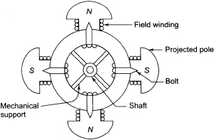
Figure 3.45 Salient Pole-type Rotor
3.14.2.2 Smooth Cylindrical Type Rotor
Figure 3.46 shows a cylindrical type rotor, which is non-salient-type. The rotor consists of a smooth solid steel cylinder having a number of slots to accommodate the field coil. In this type of rotor, the poles are not projecting out and uniform air gap is maintained. This type of rotor has small diameter and large axial lengths to keep the peripheral speeds within limits. These rotors are preferred for high-speed alternators ranging from 1,500 rpm to 3,000 rpm due to their high mechanical strength. Such high-speed alternators are known as turbo alternators. Prime movers such as steam turbines and electric motors are used to drive such types of rotors.
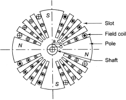
Figure 3.46 Smooth Cylindrical Type Rotor
The comparison between salient pole type and smooth cylinder type rotors is shown in Table 3.3.
Table 3.3 Comparison Between Salient Pole-type and Smooth Cylinder Type Rotors
| Salient Pole-type | Smooth Cylindrical type |
|
|
The principle of DC generators has already been introduced. The basic principle of a synchronous generator or an alternator is the same as that of the DC generator. The commutator part is not required in a synchronous generator. (The working principle of synchronous motors has been discussed in Chapter 7, Section 7.1.)
3.14.3 Classification of Synchronous Machines Based on the Prime Mover
The following are the classifications of the synchronous machines based on the type of the prime mover:
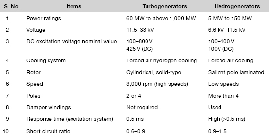
- Turbogenerators: The efficiency of these machines is found to be very high at high speeds, and hence they run at very high speeds having peripheral speed as high as 160 m/s. They are driven by steam turbines having the rotor cylindrical types made of solid steel forging of chromium-nickel-molybdenum steel to withstand centrifugal forces at high speeds. The capacity of these machines is very high (>1,000 MW).
- Hydrogenerators: The salient pole rotors are used because they are run at low speeds. They are driven by water turbines. The capacity of these machines ranges from 5 MW to 150 MW.
Table 3.4 shows the comparison between turbogenerators and hydrogenerators.
Table 3.4 Comparison Between Turbogenerators and Hydrogenerators
3.14.4 Excitation System
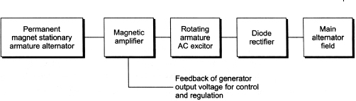
DC excitation is required for field coils both for alternators and for motors. The field coils are connected to a 125–600 V DC source to provide excitation current to field coils. In many cases, exciting current is obtained from DC generators, which are mounted on the shaft of the alternator. Figure 3.47 shows the brushless system for a high-rating alternator where field current up to 4,000 A is required.
3.14.5 Damper Windings
In salient types the poles are slotted to provide the copper bars, which are short circuited at the ends, known as damper windings. These windings reduce momentary fluctuations in speed due to load shedding, and this phenomenon is known as hunting. Damper windings are also useful for the starting of synchronous motors. Turboalternators are usually not provided with damper windings due to the presence of solid field poles, which act as efficient dampers.
3.14.6 Frequency and Synchronous Speed
The emf induced in the conductors of an alternator is alternating and hence has the sinusoidal waveform. The frequency of the induced emf is expressed as follows:
![]()
where P is the total number of poles on the alternator, f is the frequency of the emf generated in Hz and N is the speed of the rotor of the alternator in rpm.
From Equation (3.3), the speed of an alternator can be expressed as follows:
![]()
The rotor of the alternator rotates at a speed so that the frequency of the induced emf becomes![]() and this speed is known as synchronous speed. Table 3.5 shows the synchronous speed in rpm for different number of poles for frequency f = 50 Hz.
and this speed is known as synchronous speed. Table 3.5 shows the synchronous speed in rpm for different number of poles for frequency f = 50 Hz.
From Table 3.5, the synchronous speed of a machine decreases with increase in the number of poles.
Table 3.5 Synchronous Speed in rpm for Different Number of Poles for Frequency f = 50 Hz

3.14.7 Armature Windings
The windings of AC machines are open-type while that of DC machines are closed-type. Hence, the AC armature windings are different from DC windings. No closed path exists for the armature currents in AC windings itself. All the ends of the windings of AC machines are brought out on one side and the others on the other side are connected together to form the neutral point for the star connection.
Table 3.6 shows the characteristics of three-phase AC windings which are commonly used.
Table 3.6 Characteristics of Three-phase AC Windings
| Type of coil | Concentric, lap, wave |
| Overhang | Diamond, multiplane, involute and mush |
| Layers | Single, double |
| Slots | Open, closed, semi-closed |
| Connection | Star, delta |
| Phase spread | 60°, 120° |
| Slotting | Integral, fractional |
| Coil span | Full pitched, chorded |
| Circuits | Series or parallel |
| Coils | Single-turn, multiturn |
The basic condition that should be satisfied in the AC winding is that it should produce in general a symmetrical n-phase balanced system of emfs of identical magnitude, wave shape and frequency, but should be displaced in time phase by![]() except for two phases for which
except for two phases for which ![]() electrical radians.
electrical radians.
This is achieved by using identical windings for all the phase groups and arranging the groups in such a way so that they have effective space displacement of ![]() electrical radians. Usually, phase windings are arranged so that spread of each phase per pole
electrical radians. Usually, phase windings are arranged so that spread of each phase per pole ![]() . The sequence of phase bands thus formed is AC´BA´CB´, as shown in Figure 3.48(d).
. The sequence of phase bands thus formed is AC´BA´CB´, as shown in Figure 3.48(d).
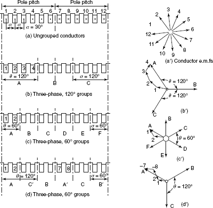
Ungrouped conductors arranged in 12 slots are shown in Figure 3.48(a). The emf induced in the conductors will be as shown in Figure 3.48(a), with each being displaced by slot pitch angle a assuming that the flux density in the gap is sinusoidal.
Let us consider that phase A and phase B are formed by conductors 1, 2, 3, 4 and conductors 5, 6, 7, 8, respectively, and remaining conductors from phase C, as shown in Figure 3.48(b). The four conductors forming any one phase will have a spread of 120° since the slot pitch is 30°. Hence, the phase difference between the three phases is generated.
The three-phase emfs formed due to the summation of emfs in each phase band (1, 2, 3, 4) will be displaced from each 120° in time phase. The resultant emf of the each phase will be less than the arithmetic sum of the component emfs, that is, ea < (e1 + e2 + e3 + e4). This is due to the spreading of the windings. The number of slots used per pole per phase is 4; that is, SPP = 4.
In Figure 3.48(c), SPP is 2 and there is six-phase grouping, each being 60° apart. In arrangement of Figure 3.48(c), single-layer winding cannot be used because of absence of return conductors left out for every one pole pitch separation.
3.14.7.1 Single-layer Winding
Single-layer windings can be divided into three types:
- spiral winding or concentric winding,
- lap winding and
- wave wining.
All the windings shown are full-pitched windings in the sense that the span from centre to centre of adjacent belts of the conductor is equal to the pole pitch. If some of the individual coils have higher or lower pitch than the average pitch, it does not alter the conclusion as to the pitch of the winding as a whole. Single-layer windings are generally used for small machines of a few kW ratings.
They are of two types: (1) concentric-type and (2) mush-type. The characteristics of three-phase single-layer windings are shown as follows:
- Concentric single-layer windings are always full-pitched windings.
- In concentric winding, even if coil span of individual coils in coil group is different from pole pitch, the effective coil span is full pitched.
- In mush winding, coil span is constant and hence shape and size of all coils is the same.
- Fractional slot windings cannot be employed for single-layer winding.
- In mush winding, coil span is always odd. For example, in two-pole, 14-slot machine, coil span is 14/2 = 7 (full pitched). But in two-pole, 12-slot machine, coil span is 12/2 = 6 since coil span is to be odd. One can use 5 or 7 slots per pole.
From Figure 3.49, we can note that an overhang design is required so that end connections are accommodated in separate tiers or planes.
Overhang is arranged in two or three planes as shown in Figure 3.49(b). For Figure 3.49(a), we have 24 slots with four poles having two-turn coil. So in this arrangement, the number of slots/pole/phase![]() . The pole pitch = total number of slots/number of poles=
. The pole pitch = total number of slots/number of poles=![]() .
.
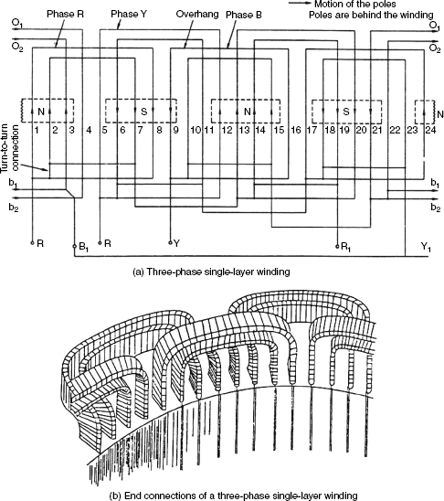
Figure 3.49 Single-layer Winding
Slot pitch angle = pole pitch/number of slots per pole ![]()
Phase spread = slot pitch angle × slot/pole/phase = 30° × 2 = 60°
In order to obtain the maximum emf in a coil, the two sides should be one pole pitch apart, that is, if one side of the coil is under the centre of north pole. Then other coil side must be under the centre of south pole (approximately 180 electrical degrees apart). This is for achieving the maximum emf per coil.
By keeping in view, the winding of the above condition is designed for three phases of Figure 3.49(a) which is explained as follows:
- For phase R: Phase R starts at slot 1 and passes through slots 8, 2 and 7 before it is taken through slots 13, 20, 14 and 19, which are situated two pole pitches apart.
- For phase Y: Now Y phase must start at 120° apart from R phase. Now the Y phase must start
 slots away from slot 1 since the slot pitch angle is 30°. Therefore, the starting slot of Y phase is 5th. Then further Y phases are completed going through slots 12, 6, 11, 17, 24, 18 and 23.
 - For phase B: Now B phase must start at 120° apart from Y phase. Now B phase must start from 9th slot and is further completed by going through slots 16, 10, 15, 21, 4, 22 and 3.
So R-Y-B are the starting points of the phases and R´Y´B´ are the end points of the phases. R´Y´B´ are joined together at a point to from the neutral point of the star-connected system. For winding to be delta connected, R´ is connected to Y, Y´ is end connected to B, and B´ is connected to R.
For the winding shown in Figure 6.49(a), the number of coil sides is similar to the number of slots, and also it is to be noted that polar groups of each phase (1, 2 and 13, 14) are two pole pitches apart. In this type of winding, the following points should be noted before designing:
- To avoid fouling of end connections, it is necessary to use two different shapes of coils.
- To make it possible that the emfs add to each other, polar groups of each phase must be connected in the same sense.
- Short pitch coils should not be used as they reduce emf.
3.14.7.2 Double-layer Winding
Two-layer windings are of two types: lap wound and wave wound. Here, we discuss the modifications that are required to give three-phase emfs. Two-layer windings are mostly applied in alternators and induction motors of a few kW ratings.
Double-layer windings are usually classified in two types:
- integral slot windings and
- fractional slot windings.
3.14.7.3 Integral Slot Winding
If the number of slots per phase (SPP) is an integer, then the winding is called an integral slot winding.
If a winding is there with 24 slots and 4 poles, then the number of slots/pole/phase ![]() (an integer). So the arrangement is integral slot winding.
(an integer). So the arrangement is integral slot winding.
If the number of slots is divisible by the number of phases then we obtain the balanced winding.
Let us consider the three-phase winding with 24 slots and 4 poles. The full pitch of the winding is ![]() .
.
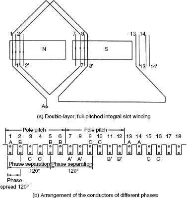
Figure 3.50 Three-phase Integral Lap Winding with 24 Slots and 4 Poles
Also, since they are six slots per pole, the slot pitch angle ![]() Now, if it is assumed that the coil span is full pitched, the upper coil side of phase A situated in slot 1 must be connected to the bottom coil side placed in slot 7 (6 + 1), as shown in Figure 3.50(a), since SPP = 2; the conductor of phase A will occupy two slots/pole as shown in Figure 3.50(b). Also, the phase spread is = 30°× 2 = 60°.
Now, if it is assumed that the coil span is full pitched, the upper coil side of phase A situated in slot 1 must be connected to the bottom coil side placed in slot 7 (6 + 1), as shown in Figure 3.50(a), since SPP = 2; the conductor of phase A will occupy two slots/pole as shown in Figure 3.50(b). Also, the phase spread is = 30°× 2 = 60°.
Based on the above logic, the winding diagram of A can be completed further from Figure 3.50(b). It can be interpreted that slots 1, 2, 7, 8, 13, 14, 19 and 20 contain coils belonging to phase A. So it can be generalized for full-pitched integral slot belonging to the same phase. Phase B is started 120° from phase A. Since the slot pitch angle is 30°, phase B is started from 5th slot (4 slots away from start of phase A), and similarly, phase C must start from 9th (5 + 4) slot.
3.14.7.4 Fractional Slot Winding
If the number of slots per pole per phase is not an integer, it is termed as fractional slot winding. But for symmetry of winding, the number of slots must be divisible by the number of phases. The various advantages of this type of winding are as follows:
- Since the number of poles is not a multiple of number of slots, the existing slotted armature can be used eliminating the saving of punching of new armature.
- High-frequency harmonics in emf and mmf waveforms are reduced.
- This allows higher flexibility in the choice of the coil span. In a machine with 44 slots and 10 poles, the pole pitch is
 . Now the coil span can be taken as 4.
The limitations of fractional slot windings are as follows:
- They are only useful for double-layer windings.
- Numbers of parallel paths are limited.
Distribution of Coils
The ratio ![]() is called as characteristic ratio of fractional slot winding. For a 42-slot and 10-pole winding, the characteristic ratio is
is called as characteristic ratio of fractional slot winding. For a 42-slot and 10-pole winding, the characteristic ratio is ![]() . The repeatable section of the winding is indicated by the highest common factor (k) between number of slots/phase and number of poles. Here, k = 2 which means winding repeats itself for 5 poles. The numerator or term Sk = 7 represents the coils per phase distributed among S poles. A tabular method is proposed for knowing the distribution of Sk(7) coils under Pk(5) poles.
. The repeatable section of the winding is indicated by the highest common factor (k) between number of slots/phase and number of poles. Here, k = 2 which means winding repeats itself for 5 poles. The numerator or term Sk = 7 represents the coils per phase distributed among S poles. A tabular method is proposed for knowing the distribution of Sk(7) coils under Pk(5) poles.
Construction of Tables
Total number of columns = 3 × Sk = 21
Total number of rows = pk = 5
The sequence of the phase belt is calculated by dividing 3Sk columns into three equal sections for a phase spread of 60°. Start from the extreme left and top square with a cross. Now, move to the right in the first row and put a square separated by Pk(5). After the first row, go to the second row and mark a cross at an interval of five squares as shown in Table 3.7.
From Table 3.7, it is interpreted that number of cells of phase A under pole 1 is 2, under pole 2 is 1 and so on, shown in Table 3.8.
Consider a three-phase, four-pole alternator having 24 slots and 2 conductors per slot. In double-layer winding, the number of slots is equal to the number of coils when there are 2 conductors per slot. Pole pitch (assuming coil span of full pitch )![]() . The number of slots/pole/phase=
. The number of slots/pole/phase=![]() . Phase spread=
. Phase spread=![]() . The distribution of conductors in the slot of phase R is shown in the tabular form below.
. The distribution of conductors in the slot of phase R is shown in the tabular form below.
Table 3.7 Distribution of Coils of Different Phases Under Various Poles
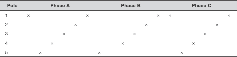
Table 3.8 Distribution of Coils of Phases Under Poles
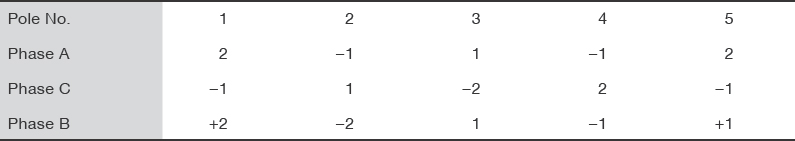
Table 3.9 Conductors Under Phase R

There are 16 conductors in phase R and these are displaced one pole pitch apart with 4 conductors per pole. The conductors under phase R are shown in Table 3.9.
The conductors in the upper layer are numbered as 1, 2, 3, etc., and are indicated by thick lines. The conductors in bottom layers are numbered by superscripts as 2´, 3´, etc., and are indicated by the bottom lines. The motion of the poles is from left to right and the direction of induced emf in the conductor under each pole is shown in Figure 3.51. Phase R is obtained with the following sequence of connections of conductors:
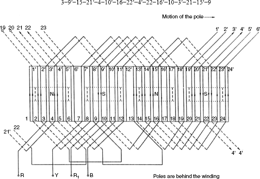
Figure 3.51 Layout of Three-phase Double-layer Ware Winding
3–9´ are connected at the coil span of 6 slots. Now, since conductors 3 and 4 come under the phase spread of R, 21´ is connected to 4. Conductors 4–10´–16´–22 are connected at a coil span of 6 slots. To facilitate end connection strap ST is used to connect 22´ and 4´. The connection of conductors 4´–22–16´–10 is in reverse direction with the coil span of –6. If we add –6 to 4´ we get –2. Now, conductors with number (–2) do not exist; total number of conductors will be –2 added to 24 = 22. So the conductor 4 is connected to conductor 22. The set 3´–21–15´–9 is similar to the set 4´–22–16´–10. The number of slots per pole is taken as 6 and the slot pitch angle is defined as follows:
![]()
Now, the phase difference between the R and Y phases is 120° and the phase difference between emfs induced in conductors of adjacent slots is 30 electrical degrees. So the separation between R and Y phases should be 4 slot pitches (i.e. 4 × 30° = 120°); for the concept discussed above, the phase Y starts from 7th conductor in 7th slot. So Y phase conductor sequence combination is as follows:
1–13´–19–1´–8–14´–20–2´–8´–2–20´–14–7´–1–19´–13
Similarly, 120° away from phase B, phase A is started. Thus, the conductors forming the phase B are as follows:
11–17´–23–5´–12–18´–24–6´–12´–6–24´–18–23´–17
Figure 3.52 shows a three-phase, double-layer, two-pole lap winding with slots per pole per phase equal to 2.
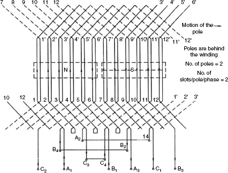
Figure 3.52 Layout of Three-phase, Double-layer Lap Winding
3.15 POLYPHASE INDUCTION MACHINES
Polyphase induction machines are generally used as motors. An induction machine can also operate as a generator. But its performance is not satisfactory for generator operation.
The stator of an induction motor consists of stator frame, stator core, polyphase distributed windings, two-end covers, bearing and so on. The stator frame consists of a symmetrical and substantial casting. The stator core is assembled in the frame under hydraulic pressure. The stator core consists of high-grade, low-loss electrical sheet stampings. The stator carries three-phase windings and is fed from a three-phase supply. Actually, it is wound for a definite number of poles. The number of poles is determined by the requirements of speed. The number of poles produced in a rotating field is given by P = 2q, where q is the number of stator slots/pole/phase. Therefore, greater the number of poles, lesser is the speed and vice versa as ![]() .
.
The rotors of induction motors are of two types: (i) squirrel-cage rotor and (ii) wound rotor/slip ring rotor.
3.15.1 Squirrel-cage Rotor
In practice, nearly 90 per cent of induction motors are squirrel-cage-type, which are the simplest and of the most rugged construction, as shown in Figure 3.53. The rotor core is made of laminated silicon steel with slots suitably punched to house the rotor bars. In small machines the punched laminations are stacked and fitted directly into a shaft. In case of large machines, a stack of annular punching of suitable cross-section area is fitted into the spider web arrangement on the shaft. The slots house insulated bars made of copper or aluminium. The solid bars are short circuited at both ends by end rings of the same material. There is no possibility to add any external resistance in series with the rotor circuit for starting purposes because the rotor bars are permanently short circuited on themselves. The rotor bars are not exactly parallel to the shaft. They are given a slight skew which helps to make the motor run quietly by reducing the magnetic hum. Another advantage is that this skew reduces the locking tendency of the rotor.
The following are the advantages of squirrel-cage induction motor:
- Cheaper in cost.
- Simple and rugged in construction.
- Low maintenance cost.
- Explosion proof.
Figure 3.53 Squirrel-cage Rotor of Induction Motor
- Due to base end rings, these machines can be cooled better.
- More pull-out torque.
- Maximum power output.
- Starting arrangement is simple.
- Speed is nearly constant.
- Overload capacity is high.
- Power factor is high.
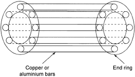
The following are the disadvantages of squirrel-cage induction motor:
- Poor starting torque due to low rotor resistance.
- Draws a large current at the time of switching.
- Very sensitive to the supply voltage.
- Power factor is low at light load.
- Speed regulation is not possible.
3.15.2 Wound Rotor
This type of rotor also has slotted stampings, which are former wound. The rotor slots in the wound rotor accommodate an insulated copper winding very much like the stator winding. The rotor windings are distributed uniformly and usually connected in star. The three ends from the star connection are brought out at the three slip rings mounted on but insulated from the shaft. This type of rotor is also called slip ring rotor as the rotor is wound with polyphase windings and carries slip rings. Figure 3.54 shows a wound rotor induction motor.
The stator of a polyphase induction motor receives electrical energy from an alternating voltage source. Therefore, it is called singly excited machine. After supply is given to the stator, a rotating flux is produced in the air gap rotating at synchronous speed. The concept of rotating magnetic field (RMF) has been discussed in Section 3.29. This flux sweeps past the rotor surface cutting the stationary rotor conductors. According to Faraday’s law of electromagnetic induction, an emf is induced in the rotor conductors due to the relative speed between the rotor and the rotating flux. Due to the relative velocity between the rotor and the RMF, the rotor will try to oppose the very cause of its induced emf as per Lenz's law. It will turn to follow the RMF. Stator winding connected to the supply is called the primary winding similar to the transformer where the rotor winding is called the secondary winding as it receives energy from the stator by mutual flux. Thus, induction motor may be taken as a generalized transformer.
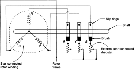
Figure 3.54 Wound Rotor Induction Motor
The following are the advantages of the wound rotor or slip ring induction motors:
- High starting torque.
- High overload capacity.
- Nearly constant speed.
- Low starting current.
The following are the disadvantages of the wound rotor induction motor:
- Low power factor at light loads.
- Lower efficiency.
- Sensitive to fluctuation in supply voltage.
- Maintenance cost is higher.
- Speed regulation is poor during operation with external resistances in the rotor circuit.
3.16 AIR GAP
The main source of low power factor at which induction motor operates is the air gap between the stator and the rotor. This air gap increases the reluctance between the stator and the rotor, which enhances the magnetizing current for production of the given mutual flux between the stator and the rotor for a given supply voltage. Therefore, the no-load current of an induction motor becomes 30 to 40 per cent of full-load current, which is remarkably larger than the no-load current of a transformer for a given kVA rating. The air gap in an induction motor should be made small so that the induction motor gives better performance. The small air gap may result mechanical problems in addition to the noise and losses at the slot tooth faces.
3.17 PRINCIPLE OF OPERATION OF THREE-PHASE INDUCTION MOTOR
An induction motor with one slot/pole/phase with the stator and rotor wound for three phases and two poles is shown in Figure 3.55. Figure 3.56 shows that the rotor of the induction motor is open circuited initially and the three-phase supply is given to the stator. This produces an rotating magnetic field (RMF) in the air gap between the stator and the rotor, which rotates at synchronous speed. This RMF induces an emf in the stator winding, which balances the supply voltage. This RMF also induces an emf in the rotor winding. No rotor current flows in spite of emf induced in it because it is open circuited. Due to transformer action between the stator and the rotor, the frequency of the induced emf between the stator and the rotor remains same and the rotor remains stationary in the RMF. Therefore, the machine behaves like a transformer, where the stator resembles as a primary and the rotor resembles as a secondary and the induced emfs in both the stator and the rotor have the same frequency.
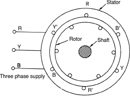
Figure 3.55 Induction Motor
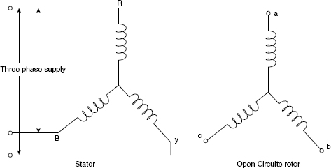
Figure 3.56 Rotor Winding Open Circuited
Figure 3.57 shows that the rotor of the induction motor is short circuited and there will be induction of balanced three-phase currents in the rotor due to the induced emf in the rotor, which produce RMF of the same speed as that of the stator in space. The torque is produced due to interaction between stator and rotor mmfs. It can be said that the rotor behaves like a current-carrying conductor, which is placed in the RMF of the stator. Hence, it will experience a torque whose direction will be as per Lenz’s law. The direction of this torque is such that it will rotate the rotor in the direction of the RMF and the rotor starts to rotate in the same direction of the RMF. It will try to catch up the speed of RMF. But the rotor will not be able to attain the synchronous speed. If it attains the synchronous speed, there will be no relative motion between the rotor conductors and RMF. Hence, the induced emf and the corresponding induced current in the rotor become zero, resulting no torque developed on the rotor. The speed of the rotor decreases. When the rotor speed falls below the speed of RMF, a torque will be experienced by the rotor due to induced current in it. Therefore, an average speed (Ns) attained by the rotor is less than the speed (Ns) of RMF.
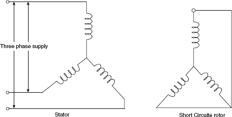
Figure 3.57 Rotor Winding Short Circuited
3.18 SYNCHRONOUS SPEED AND SLIP IN INDUCTION MOTOR
3.18.1 Synchronous Speed
If a balanced three-phase supply is fed to the stator of an induction motor, an RMF is produced in the air gap between the stator and the rotor, which revolves in space at a speed known as synchronous speed (Ns). It is related to the stator supply frequency f and can be expressed as follows:
where Ns is the synchronous speed of the RMF, P is the number of poles on the stator and f is the frequency of the stator supply voltage.
Equation (3.5) can also be expressed as follows:
Table 3.10 shows the synchronous speed (Ns) for different number of poles (P) along with the probable speed attained by the rotor on full load for a given supply frequency (f = 50 Hz).
Table 3.10 Values of Ns and Nr for Different Number of Stator Poles (P)
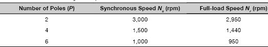
3.18.2 Slip in Induction Motor
The speed (Nr) of the rotor is always less than the synchronous speed (Ns). The slip in an induction motor is the difference in speed of Ns and Nr. Figure 3.58 shows the variation of speed and slip with torque of an induction motor. The speed of an induction motor is AC when the torque is OA and the corresponding slip is AB. There is linear increase of slip of an induction motor with torque at moderate loads. The slip in per unit is expressed as follows:
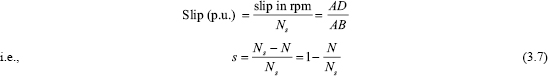
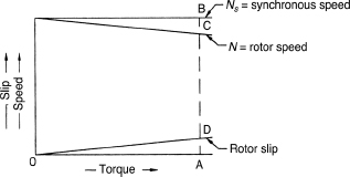
Figure 3.58
The slip for large size motors at full load varies from 2 per cent to 4 per cent, while for small motors its value can be as high as 8 per cent. Practically, induction motor can be taken as constant speed motors in spite of slip. The speed control of induction motor is more complicated and expensive than the methods used for the speed control of DC shunt motors although both of them have similar speed-torque characteristic. From Equation (3.8), we have s = 0 for N = Ns on no-load and s = 1 for N = 0 at the time of starting. Therefore, the slope of an induction motor varies from 0 (on no-load) to 1 (at the time of starting).
Example 3.3 A 16-pole, three-phase alternator is coupled to an engine running at 375 rpm. It supplies to an induction motor that has a full-load speed of1,450 rpm. Find the slip and the number of poles of the motor.
Solution
Synchronous speed (Ns) = 375 rpm
Number of poles = 16
![]()
The speed of the induction motor is 1,450 rpm. Since an induction motor runs at a speed less than its synchronous speed under normal operating conditions, the synchronous speed is 1,500 rpm for a frequency of 50 Hz.
∴ Ns = 1500rpm
![]()
3.19 FREQUENCY OF ROTOR CURRENTS
The rotor of an induction motor runs at a speed (Nr), which is less than the synchronous speed (Ns) of rotating magnetic field. The frequency of the induced currents in the rotor of the induction motor depends on the difference between the speeds Ns and N. If the frequency of the induced currents in the rotor is f2, it can be expressed as follows:
![]()
Equation (3.9) shows the relation between the frequency of the rotor current and the supply frequency. If the normal full-load slip of an induction motor is of the order of 1 to 4 per cent, the frequency ( f2) of the induced currents in the rotor will be 1–4 Hz when the supply frequency ( f ) is 50 Hz.
3.20 SPEED OF THE ROTOR MMF
It is known that a revolving magnetic field is produced when a balanced three-phase supply is applied to stator winding of the three-phase induction motor. The axis of this revolving field rotates at synchronous speed relative to stator conductors. In a similar manner, the three-phase induced current in the rotor produces a resultant emf. The axis of this emf rotates in the direction of the rotation of the rotor at a speed (Ns– N) with respect to rotor conductors. The rotor rotates in the air gap at a speed N with respect to the stator core, which is less than the synchronous speed. Therefore, the speed of the resultant rotor emf in space = (Ns – N) + N = Ns. Therefore, the resultant rotor mmf rotates at a speed, which is same as the resultant stator mmf in space. Hence, the mmfs produced by the stator and the rotor are stationary relative to each other in space. They differ only in phase where the phase angle between the two mmfs increases with the increase of load. The phase difference between the two mmfs becomes ![]() where θ2 is the internal power factor of the rotor.
where θ2 is the internal power factor of the rotor.
3.21 ELECTRICAL AND MECHANICAL DEGREES
The conductor rotates at a uniform angular velocity, shown in Figure 3.59(a). The emf induced in the conductor is zero at ‘a’ because the corresponding flux is zero at ‘a’. The emf induced in the conductor is maximum at ‘b’. because the corresponding flux is maximum at ‘b’. The emf induced in conductor is zero at ‘c’ because the corresponding flux is zero at ‘c’. The emf induced in conductor is maximum at ‘d’ because the corresponding flux is maximum at ‘d’. The flux entering the stator or leaving the rotor is assumed to be positive. Figures 3.59(b) and 3.59(c) show the corresponding flux and emf variations, respectively. For one complete rotation of the rotor, one cycle of emf is obtained for two poles. Figure 3.59(d) shows four poles. Figures 3.59(e) and 3.59(f) show the corresponding flux and emf variations, respectively. For one complete rotation of the rotor, two cycles of emf will be generated.
One revolution indicates 360 mechanical degrees and one cycle of emf indicates 360 electrical degrees. So two cycles of emf is equivalent to 720 electrical degrees.
720 electrical degrees = ![]() × (360 mechanical degrees)
× (360 mechanical degrees)
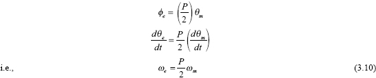
where ωe is the angular velocity in electrical radians per second and ωm is the angular velocity in mechanical radians per second.
For a four-pole machine, two cycles are generated for one revolution of the rotor. Therefore, for a P-pole machine, P/2 cycles per second are generated in one revolution per second. Therefore, we can conclude that for a P-pole machine, in ‘n’ revolution/second, ![]() cycles/second are generated. But cycles/second is termed as frequency (f) of the generated emf wave.
cycles/second are generated. But cycles/second is termed as frequency (f) of the generated emf wave.
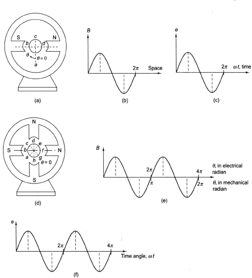
Figure 3.59 Electrical and Mechanical Degrees
If the speed n is in rpm,
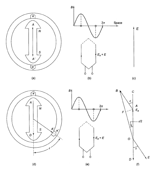
Figure 3.60 Full-pitched and Fractional-pitched Winding
3.22 PITCH FACTOR
Figures 3.60(a) and 3.60(d) show full-pitched and fractional pitched coils, respectively. In full-pitched winding, the resultant emf is 2E as shown in Figures 3.60(b) and 3.60(c). It is not equal to 2E in fractional pitched winding. It is less compared to the resultant emf in full-pitched winding, shown in Figures 3.60(e) and 3.60(f).
In the fractional pitched winding, emfs induced in the two coils are E (= OA) and ![]() .
.
From the phasor diagram, Figure 3.60(f), the pitch factor for fractional pitched winding can be calculated as follows:
∠DOE = ∠BAC = ∊
Now ∠BAO = 180°–∊
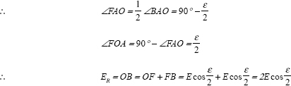
The ratio of resultant emf of a fractional-pitched coil to the resultant emf for the same coil when it is full-pitched,
![]()
![]()
For nth harmonic,
![]()
Fractional pitched windings have the following advantages:
- The cost of the machine is less due to reduction of copper in overhang.
- There is reduction of harmonics in the generated emf wave. So, the output emf wave becomes almost a sine wave.
Example 3.4 Find the pitch factors of the following windings:
- 32 stator slots, 4 poles, coil span is 1–7.
- 72 stator slots, 8 poles, coil span is 1–8.
Solution
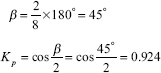
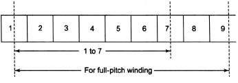

3.23 DISTRIBUTION FACTOR
Armature winding is not usually concentrated in a single slot for rotating electrical machines. The armature winding is distributed uniformly in the slots of the armatures. The main advantages of distribution of the windings in slots are as follows:
- The output emf becomes almost a sine wave as there is reduction of harmonics in the generated emf wave.
- It increases rigidity and mechanical strength of the winding.
- There is full utilization of the armature iron and copper.
The ratio of emf induced in a distributed winding to the emf induced if the winding is concentrated is called distribution factor/breadth factor.
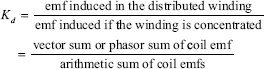
The value of Kd is always less than unity.
Suppose n = number of slots/pole, q = number of slots/pole/phase, γ = angular displacement between the slots=![]() , E = induced emf in each coil side.
, E = induced emf in each coil side.
The emf induced in different coils of one phase under one pole is shown in Figure 3.61 by AB, BC, CD, DE, etc., that are equal in magnitude but differ in phase (say α) from each other. Let the bisectors of AB, BC, CD, DE, etc., meet at a common point O. The point O is called the circumcentre of the circle having AB, BC, CD, DE, etc., as the chords.
Here, emf induced in each coil side is given by
![]()
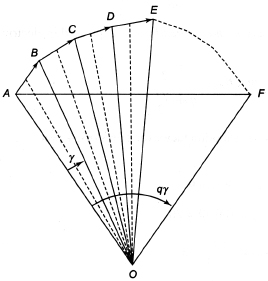
Figure 3.61 Calculation for Distribution Factor
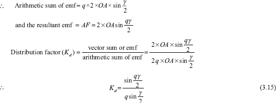
The term qγ is also known as the phase spread and is expressed in electrical radians.
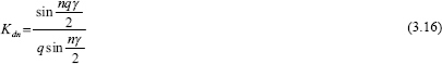
Example 3.5 Calculate the distribution factor for a 36-slot, four-pole, single-layer, three-phase winding.
Solution
Slots/pole (n) = 36/4 = 9
γ = 180°/9 = 20°
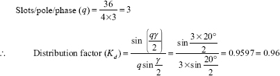
3.24 WINDING FACTOR
It is defined as the product of distribution factor (Kd) and pitch factor (Kp). It is denoted by the symbol Kw.
3.25 FLUX PER POLE
Figures 3.62(a) and 3.62(b) show the field windings on the rotor and the stator, respectively. In both cases cylindrical rotors have been considered. It does not make any difference if salient poles are considered. The starting of space angle is taken from field winding axis. When θ = 0°, flux density B is maximum. For θ = 90°, flux density is minimum. When θ = 180°, B is again maximum but in the opposite direction. For θ = 270°, flux density is minimum. B is again maximum for θ = 360° and so on. The flux density wave can be written as follows:
An elemental angle dθ at an angle θ from the field winding axis is considered to calculate the flux per pole. If l be the axial length of armature core, the curved area of the elemental area is lrdθ, where r is the radius of the rotor. The portion of flux passing through the elemental surface area lrdθ is given by
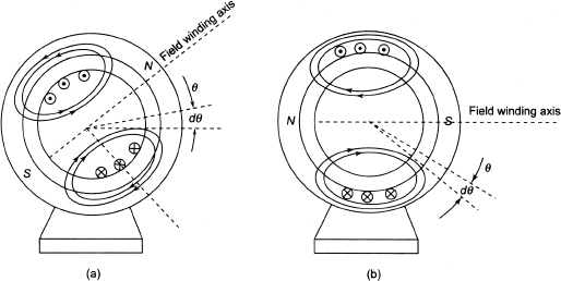
Figure 3.62 Calculation of Flux per Pole
dΦ = Blrdθ
Total flux can be obtained by integrating Equation (3.19) from θ = –π/2 to +π/2 as follows:
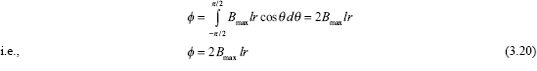
The value of the flux per pole is obtained in Equation (3.20) for a two-pole machine.
Per pole area for a two-pole machine![]()
Therefore, per pole area for a P -pole machine![]()
Now for a two-pole machine, flux per pole (with pole area πlr) = 2Bmaxrl
Therefore, for a P-pole machine, flux per pole![]()
3.26 GENERATED EMF IN FULL-PITCHED COIL
Figures 3.63(a) and 3.63(b) show a two-pole machine. In Figures 3.62(a) and3.62(b), the pole is on the stator and the rotor, respectively. For simplicity two-pole machines have been considered. It is also assumed that there is an N-turn full-pitched armature coil. From Figure 3.63, it is seen that when the field winding axis coincides with the stator coil axis, flux linking with the coil is maximum; that is, at t = 0, θ = ωrt = 0 and the flux passing through the coil is maximum, that is, Φcos 0° or Φ. At time angle θ = ωrt = 90°, Φ linking the coil is minimum. Again at θ = ωrt = 180°, Φ linking the coil is maximum but in the opposite direction. So the flux linkage ψ with the full-pitched armature coil having N turns per phase at any instant t is given by
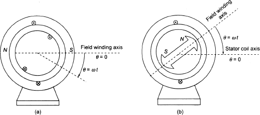
Figure 3.63 Illustration of Generated emf in a Single-turn Full-pitched Coil
Since flux Φ is time invariant, the term ![]() called transformer-voltage term is zero. The term NωrΦsinωrt called speed-voltage term will exist. Equation (3.22) can be expressed as follows:
called transformer-voltage term is zero. The term NωrΦsinωrt called speed-voltage term will exist. Equation (3.22) can be expressed as follows:
From Equation (3.23), we conclude that the induced emf lags behind the flux by an angle 90°.
The emf generated in a short-pitched distributed winding is given by
Equation (3.24) suggests that the induced emf lags behind the flux by an angle 90°.
3.27 EMF GENERATED IN AC MACHINES
In rotating electrical machines, the armature turns are not concentrated in slots. The armature turns are usually distributed in slots to utilize the armature periphery completely. Distribution of the coils in different slots helps in reduction of harmonics. Besides the distribution, the windings are made short pitch.
The emf generated in a short pitch distributed winding is given by
where Nph is the number of turns per phase.
Example 3.6 A three-phase, 16-pole alternator has a star-connected winding with 144 slots and 10 conductors per slot. The flux per pole is 0.03 Wb sinusoidally distributed and speed is 375 rpm. Find the frequency and the phase emf and line emf. Assume coil is full pitched.
Solution
Here, N= 375 rpm, P =16, Kp =1, Φm = 0.03 Wb
Slots = 144, conductor per slots = 10
∴Slots/pole ![]()
∴Angular displacement between the slots ![]()
∴Slots/pole/phase ![]()
∴Distribution factor 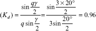
Since the coil is full pitched, Kp = 1
∴Number of conductors/phase![]()
∴Number of turns/phase![]()
∴Induced emf/phase (Eph) is given by
Eph = 4.44 KpKdf ΦmN
Eph = 4.44 ×1 ×0.96 ×50×0.03 ×240 = 1,534.46V
Line voltage (EL) = √3 Eph = √3 × 1534.46 = 2657.77V
3.27.1 Synchronous Machines
3.27.1.1 Armature Winding
The field winding is excited with DC so that the flux does not vary with time. Let Nph be the total number of series turns per phase of the polyphase armature winding. The emf generated in any one phase is given by
Let the time origin be taken from the instant when flux linkages with phase are maximum. The emf induced for phase a can be written as follows:
For phases b and c,
The relative velocity between the flux density wave and armature winding must be synchronous because the synchronous machine runs at synchronous speed (Ns). In a synchronous machine the rotational frequency is ![]() Hz for which the machine has been designed. The emf generated per phase of a synchronous machine is given by
Hz for which the machine has been designed. The emf generated per phase of a synchronous machine is given by
3.27.1.2 Field Winding
Let Vf be direct voltage applied to the field winding. We can write
![]()
3.27.2 Induction Machines
3.27.2.1 Stator
If a balanced polyphase voltage is applied to the stator winding, it produces an RMF of constant amplitude in the air gap. This speed is called synchronous speed. There is relative velocity between the constant amplitude rotating field and the stationary stator winding. So an emf is induced in the stator winding. The magnitude of this induced emf in any one phase is given by
where f is the frequency of the applied voltage and Nph is the stator series turns per phase.
3.27.2.2 Rotor
In an induction motor, the RMF in the air gap rotates at a synchronous speed ![]() rpm where P is the number of stator poles. Since the rotor rotates at a speed Nr rpm less than the synchronous speed in the same direction of the RMF, the relative speed between the RMF and the rotor is (Ns – Nr)rpm. Ns – Nr rpm is called the slip speed.
rpm where P is the number of stator poles. Since the rotor rotates at a speed Nr rpm less than the synchronous speed in the same direction of the RMF, the relative speed between the RMF and the rotor is (Ns – Nr)rpm. Ns – Nr rpm is called the slip speed.
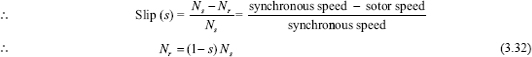
The frequency of induced or generated emf in rotor coil is fr = sf.
So the emf induced or emf generated in one rotor coil is
where Nph is the rotor series turns/phase.
The frequency of the rotor emf is sf, which is called the slip frequency. This is denoted by fr.
If the rotor is being rotated at a speed (Nr rpm) in the opposite direction of the rotating field (Ns rpm), the slip is given by
3.27.3 A General Expression for the emf of Synchronous Generator
The emf generated per phase in a full-pitched alternator having concentrated winding is expressed by
If kw be the winding factor, the expression for the emf induced per phase is expressed by
For non-sinusoidal flux density, harmonics will be present in the generated emf. The harmonics can be estimated using Fourier analysis of the flux density waveform. Figure 3.64 shows a general trapezoidal waveform of flux density. Using the suitable value of θ and γ, all other waveforms can be deduced from it.
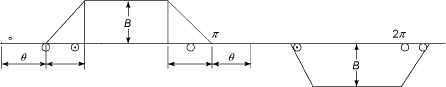
Figure 3.64 Fractional-pitched Trapezoidal Waveform
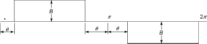
Figure 3.65 Fractional-pitched Rectangular Distribution When γ = 0
Figure 3.64 shows fractional pitched trapezoidal waveform.
Bn = magnitude of the nth harmonic
![]()
B1 = magnitude of the fundamental
![]()
Figure 3.65 shows fractional pitched rectangular waveform.
Bn = magnitude of the nth harmonic ![]()
B1 = magnitude of the fundamental ![]()
Figure 3.66 shows full-pitched rectangular waveform.
Bn = magnitude of the nth harmonic ![]()
B1 = magnitude of the fundamental ![]()
Figure 3.67 shows full-pitched triangular distribution.
Bn = magnitude of the nth harmonic ![]()
B1 = magnitude of the fundamental ![]()
Figure 3.66 Full-pitched Rectangular Waveform
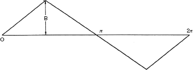
Figure 3.67 Full-pitched Triangular Distribution
Therefore, the resultant emf of the waveform containing harmonics is expressed by
where E1, E2, …, En are the fundamental, second, …, and nth harmonics.
3.28 EMF GENERATED IN DC GENERATOR
The emf generated in a DC generator is given by
where Φ = flux/pole, P = number of generator poles, Z = total number of armature conductors, A = number of parallel paths, N = speed of armature in rpm.
For derivation of Equation (3.39), see Figure 4.5, Chapter 4.
3.29 CONCEPT OF ROTATING MAGNETIC FIELD
The stator of synchronous and induction motor may be star or delta connected. The three-phase windings are displaced from each other by an angle 120°. Figure 3.68 shows that the three-phase windings are supplied by a balanced three-phase supply having phase sequence R–Y–B. The current through the three windings is displaced from each other by an angle of 120° electrical. The mathematical expressions for instantaneous values of the three fluxes are given by
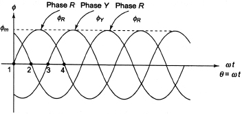
Figure 3.68 Waveform of Fluxes
Figure 3.68 shows the waveform of fluxes. The resultant flux is ![]() .
.
Let us consider the following cases.
3.29.1 Case 1: ωt = θ = 0°
Substituting θ=0° in Equations (3.40)–(3.42), we have
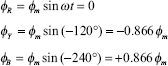
Figure 3.69 shows the phasor addition of the above three fluxes.
From Figure 3.69, we have
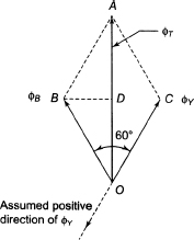
Figure 3.69 Phasor Addition of Fluxes: Case 1
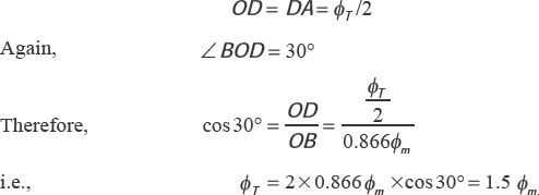
∴ The magnitude of ΦT is 1.5 Φm and its position is vertically upwards.
3.29.2 Case 2: ωt = θ = 60°
Substituting θ = 60° in Equations (3.40)–(3.42), we have
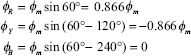
Figure 3.70 shows the phasor addition of the above three fluxes. From Fig. 3.70, we have
OD = DA = ΦT/2
Again, ∠BOD = 30°
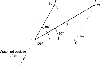
Figure 3.70 Phasor Addition of Fluxes: Case 2
∴ The magnitude of ΦT is 1.5 Φm and it is rotated through 60° in space in the clockwise direction compared to its previous position in Case 1.
3.29.3 Case 3: ωt = θ = 120°
Substituting θ = 120° in Equations (3.40)–(3.42), we have
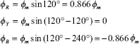
Figure 3.71 shows the phasor addition of the above three fluxes. From Figure 3.71, we have
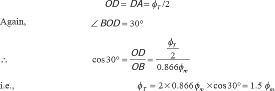
∴ The magnitude of ΦT is 1.5 Φm and it is rotated through 120° in space in the clockwise direction compared to its previous position in Case 1.
3.29.4 Case 4: ωt = θ = 180°
Substituting θ = 180° in Equations (3.40)–(3.42), we have
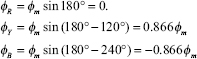
Figure 3.72 shows the phasor addition of the above three fluxes. From Figure 3.72, we have
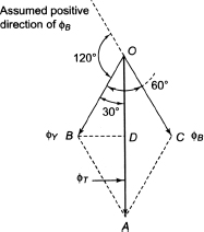
Figure 3.72 Phasor Addition of Fluxes: Case 4
The magnitude of ΦT is 1.5 Φm and it is rotated through 180° in space in the clockwise direction compared to its previous position in Case 1.
Therefore, rotating magnetic flux is produced when three stationary windings are excited by balanced three-phase AC supply. The produced resulting field is called rotating magnetic field which rotates at a synchronous speed ![]() where f is the frequency of the supply in Hz and P is the number of poles for which the winding is wound.
where f is the frequency of the supply in Hz and P is the number of poles for which the winding is wound.
Figure 3.73 shows the directions of rotation of the RMF. The RMF rotates in the clockwise direction when phase sequence is R–Y–B, while it rotates in the anticlockwise direction for phase sequence R–B–Y.
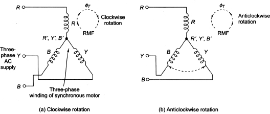
Figure 3.73 Direction of Rotation of RMF
Please see Appendix C for mmf of distributed windings and Appendix D for torque in AC and DC machines.
ADDITIONAL SOLVED PROBLEMS
Example 3.7 A three-phase induction motor has two poles and is connected to 400 V, 50 Hz supply. Calculate the actual rotor speed and rotor frequency when the slip is 4 per cent.
Solution
P = 2, s = 4% = 0.04, f = 50Hz
Synchronous speed ![]()
Rotor speed (Nr) = Ns (1 - s) = 3,000 × (1 - 0.04) = 2,880 rpm
Rotor frequency (fr) = sf = 0.04 × 50 = 2 Hz
Example 3.8 A three-phase induction motor runs at almost 1,000 rpm at no-load and 950 rpm at full load when supplied with power from a 50 Hz three-phase line. Calculate the following:
- How many poles does the motor have?
- What is the percentage slip at full load?
- What is the corresponding frequency of rotor voltage?
- What is the corresponding speed of the rotor field with respect to the rotor?
- What is the corresponding speed of the rotor with respect to the stator?
- What is the corresponding speed of the rotor field with respect to the stator field?
- What is the rotor frequency at the slip of 10 per cent?
Solution
N0 = 100rpm, Nr = 950rpm, f = 50Hz
Here, no-load speed of the motor is almost 1,000 rpm. Therefore, synchronous speed near to 1,000 rpm is 1,000 rpm.
- Poles on motor,
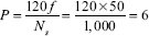
- Percentage slip at full load,
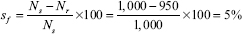
- Frequency of rotor voltage,
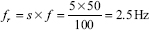
- Speed of rotor field with respect to rotor
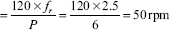
- Speed of rotor with respect to stator = 950 rpm (since stator is stationary)
- Rotor field and stator field are revolving at the same speed of 1,000 rpm. Therefore, speed of rotor field with respect to stator field is zero
- Rotor frequency at the slip of 10%,
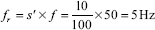
Example 3.9 A three-phase, four-pole, 50 Hz induction motor has a slip of 2 per cent at no-load and 4 per cent at full load. Calculate (i) synchronous speed, (ii) no-load speed and (iii) full-load speed.
Solution
P = 4, f = 50 Hz, s0 = 2% and sfl = 4%
Example 3.10 The stator of a three-phase, 16-pole alternator has 144 slots, and there are four conductors per slot connected in two layers. The conductors of each phase are connected in series. If the speed of the alternator is 375 rpm, calculate the emf induced per phase. Resultant flux in the air gap is 5 × 10⁻² Wb per pole sinusoidal distributed. Assume the coil span as 150° electrical.
Solution
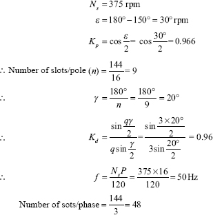
Here, number of conductors per slot = 4
∴ Number of conductors in the series/phase (Z) = 48 × 4 = 192
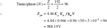
Example 3.11 A four-pole, three-phase, 50 Hz star-connected alternator has 60 slots with four conductors per slot. Coils are short pitched by three slots. If the phase spread is 60°, find the line voltage induced for a flux per pole of 0.943 Wb distributed sinusoidally in space. All the turns per phase are in series.
Solution
![]()
Hence, phase spread (qγ) = 60°
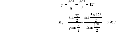
The number of slots per phase ![]()
Since the coil is short pitched by three slots,
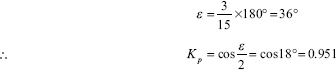
∴Number of conductors/phase![]()
∴Number of turns/phase (N) = Z/2 = 40
∴emf induced per phase (Eph) = 4.44 Kp Kd f ΦN
= 4.44×0.951×0.957×50×0.943× 40 = 7621.09V
∴Line voltage ![]()
Example 3.12 Calculate the rms value of the induced emf per phase of a 10-pole, three-phase, 50 Hz alternator with two slots per pole per phase and four conductors per slot in two layers. The coil span is 150°. The flux per pole has a fundamental component of 0.12 Wb and a 20 per cent of third harmonic component.
Solution
- Fundamental emf
Here, ∊ = 180° - 150°= 30°
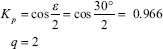
∴ Number of slots/pole = 2 × 3 = 6
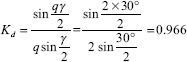
Number of conductors per phase (Z) = 10 × 2 × 4 = 80
Number of turns per phase
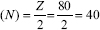
∴ (Eph) = 4.44 Kp Kd f ΦN
= 4.44 × 0.966 × 0.966 × 50 × 0.12 × 40 = 994.37V
- Third harmonic emf
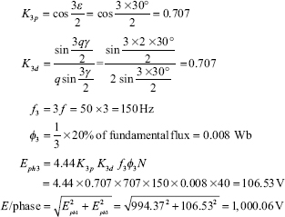
Example 3.13 A three-phase, four-pole, 50 Hz star-connected alternator has 60 slots with two conductors per slot and has armature winding of the double-layer type. Coils are short-pitched; that is, if one coil side lies in slot number 1, the other coil side lies in slot number 13. Find the useful flux per pole required to induce a line voltage of 6.6 kV.
Solution
Number of poles (P) = 4
Conductors/slot = 2, EL, = 6.6 kV
Number of slots = 60
Let the useful flux per pole be Φ
Number of slots/pole![]()
Number of slots/pole/phase![]()
Number of conductors connected in series/phase![]()
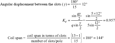
Short pitch angle (∊) = 180° – 144° = 36°
![]()
Since EL = √3 × 4.44 Kp Kd fΦN
![]()
∴ Useful flux/pole = 0.943 Wb
Example 3.14 A three-phase, 20-pole, star-connected alternator has the following data: number of slots = 240; conductors/slot = 10 (conductors of each phase are connected in series); coil span 150 electrical degrees; speed of the alternator = 300 rpm, flux/pole = 56 mWb.
Calculate the following:
- frequency of induced emf,
- pitch factor,
- distribution factor,
- winding factor,
- number of turns per phase,
- phase voltage and
- line voltage.
Solution
Given:
Number of poles (P) = 20
Number of slots = 240
Conductors/slots = 10
Coil span = 50
Synchronous speed (Ns) = 300 rpm
Flux/pole (Φ) = 56 mWb
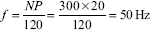
- ∊= 180° – 150°= 30°
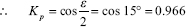
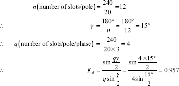
- Kw = Kp Kd = 0.966 × 0.957 = 0.924
- Number of conductors/phase

∴ Number of turns/phase

- Eph = 4.44fΦNKw = 4.44×50×56 ×10-3×400 ×0.924 = 4,594.86 V
- EL = √3 Eph = 7958.54V
SIGNIFICANT POINTS
If the speed N is in rpm, ![]()
Pitch Factor:
![]()
For nth harmonic,
![]()
The fractional pitched windings have the following advantages:
- Cost of the machine is less due to reduction of copper in overhang.
- There is reduction of harmonics in the generated emf wave. So, the output emf wave becomes almost a sine wave.
Distribution factor (Kd)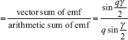
The term qγ is also known as the phase spread and is expressed in electrical radians.
For the nth harmonic, 
Winding Factor:
It is defined as the product of distribution factor (Kd) and pitch factor (Kp). It is denoted by the symbol Kw.
∴ Kw = Kd × Kp
The emf generated in a short pitch distributed winding is given by
E = 4.44 f NphΦ Kp Kd
Therefore, a P-pole machine, flux per pole is given by ![]()
SHORT QUESTIONS AND ANSWERS
Q.1 State the types of armature slots.
Ans. Open-type and main-type are the two types of armature slots.
Q.2 What types of materials are used generally in armature winding?
Ans. Conducting materials are used in the form of wires, and insulating materials are used in the form of sleeves, varnish and so on.
Q.3 What is called armature conductor?
Ans. The part of the wire lying in the armature slot and cutting the magnetic lines of force when the armature rotates is called the armature conductor.
Q.4 What do you mean by coil span?
Ans. The distance measured in terms of armature slots or armature conductors between the centre of the two sides of the coil is termed as coil span.
Q.5 What do you mean by pole pitch, conductor, coil, coil pitch and front pitch and back pitch?
Ans. Pole pitch: It is defined as the number of armature conductors per pole. If there are 80 conductors and 8 poles, pole pitch is 80/8 = 10.
Conductor: It is defined as the length of a wire lying in the magnetic field.
Coil: Two conductors with their end connections form one coil. The coil may be single-turn coil or multiturn coil. The end connections are called overhang.
Coil pitch (Ys): It is defined as the distance between two sides of a coil in terms of armature slots. In other words, it is defined as the periphery of the armature between two sides of a coil. If the coil pitch is equal to the pole pitch, the winding is said to be full pitched. Otherwise, it is called fractional pitch.
Front pitch: It is defined as the distance between the second conductor of one coil and the first conductor of the next coil.
Back pitch: It is defined as the distance measured in terms of armature conductors that a coil advances on the back of the armature. The distance in slots between the centres of the two adjacent poles is known as pole pitch.
Q.6 What do you mean by full-pitched and fractional pitched windings?
Ans. If the pitch factor is one, the winding isw termed as full pitch, and if it is less than unity, the winding is termed as fractional pitch.
Q.7 State the advantages of fractional pitched windings.
Ans. Fractional pitched windings have the following advantages:
- Cost of the machine is less due to reduction of copper in overhang.
- There is reduction of harmonics in the generated emf wave. So, the output emf wave becomes almost a sine wave.
Q.8 What do you mean by distribution factor?
Ans. The ratio of emf induced in a distributed winding to the emf induced if the winding is concentrated is called distribution factor or breadth factor.
Q.9 State the advantages of distributed windings.
Ans. The main advantages of distribution of the windings in slots are as follows:
- The output emf becomes almost a sine wave as there is reduction of the harmonics in the generated emf wave.
- There is increase in rigidity and mechanical strength of the winding.
- There is full utilization of the armature iron and copper.
Q.10 State the difference between single-layer and double-layer windings.
Ans. One conductor or one coil side is placed in each armature slot in a single-layer winding, while two conductors or two coil sides are placed in each armature slot in a double-layer winding.
SUPPLEMENTARY PROBLEMS
1. A four-pole, three-phase induction motor is supplied from 50 Hz supply. Find its synchronous speed. Determine its full-load slip if it has a speed of 1,420 rpm on full load.
[Ans. 1,500 rpm, 5.34%]
2. A four-pole, three-phase, 50 Hz star-connected induction motor has a full-load slip of 6 per cent. Determine full-load speed of the motor.
[Ans. 1,410 rpm]
3. A four-pole, three-phase, 50 Hz induction motor runs at a speed of 1,460 rpm. Determine the frequency of the induced emf in the rotor under this condition.
[Ans. 1.34 Hz]
4. A four-pole, three-phase induction motor is supplied from 50 Hz AC supply. The frequency of induced emf in the rotor is 2.5 Hz on full load. Calculate the full-load slip and the corresponding speed.
[Ans. 5%, 1,425 rpm]
5. A four-pole, three-phase alternator has 36 armature slots. It is using an armature winding, which is short pitched by one slot. Find its pitch factor.
[Ans. 0.9848]
6. A three-phase, eight-pole alternator has 120 slots. Determine its distribution factor.
[Ans. 0.957]
7. A six-pole, three-phase, 50 Hz alternator has 12 slots per pole and four conductors per slot. The winding is 5/6 pole pitch. There is 0.025 Wb entering the armature from each north pole and this flux is sinusoidally distributed along the air gap. The armature coils are connected in series. The winding is star connected. Determine the open circuit emf of the alternator. Find the breadth factors for third and fifth harmonics.
[Ans. 246.67 V, 0.654, 0.355]
8. An alternator runs at 250 rpm and generates an emf at 50 Hz. There are 216 slots, each connecting five conductors. The winding is distributed and full pitched. All the conductors of each phase are in series and flux per pole is 30 mWb which is sinusoidally distributed. If the winding is star connected, calculate the value of the induced emf available across the terminals.
[Ans. 1,992.70 V]
9. A three-phase, 16-pole, star-connected alternator has 144 slots on the armature periphery. Each slot contains 10 conductors. It is driven at 375 rpm. Determine the frequency of the induced emf and flux per pole if the line value of induced emf across the terminal is 2,657 V.
[Ans. 50 Hz, 30 mWb]
10. A three-phase, eight-pole, star-connected alternator has 120 stator slots and each slot has 10 conductors. The coil span is 12 slots. If the flux/pole is 0.12 Wb, calculate the emf induced between the lines.
[Ans. 8,389.7 V]
MULTIPLE-CHOICE QUESTIONS AND ANSWERS
- The purpose of a brush in a DC machine is to
(a) collect current from the commutator (b) collect voltage from the commutator (c) provide interaction between segments of the commutator (d) clean the commutator - If P be the number of poles, f be the frequency in Hz, N be the speed in rpm, the relationship among the three for a synchronous alternator is given by

- For a P-pole machine, the relation between electrical and mechanical degrees is given by

- A coil consists of
(a) two conductors (b) two coil sides (c) two turns (d) four turns - The main advantage of distributing the winding in slots is to
(a) add mechanical strength to the winding (b) reduce the amount of copper required (c) reduce the harmonics in the generated emf (d) reduce the size of the machine - The distribution factor is defined as the ratio of
- arithmetic sum of coil emf to phase sum of coil emf
- phasor sum of the emf per coil to the arithmetic sum of emf per coil
- phasor sum of coil emfs to the arithmetic sum of coil emf
- phasor sum of coil emf to the per phase voltage
- The pitch factor in a rotating electrical machine is defined as the ratio of resultant emf of a
(a) full-pitched coil to that of a chorded coil (b) full-pitched coil to the phase emf (c) chorded coil to that of a full-pitched coil (d) chorded coil to the phase emf - The main advantage of using fractional pitched winding is to reduce the
(a) harmonics in generated emf (b) amount of copper in the winding (c) size of the machine (d) cost of the machine - In an alternator, the frequency per revolution is equal to the
(a) number of poles (b) number of armatures (c) number of pairs of poles (d) fitting - A 90-slot stator has a three-phase, six-pole, whole coiled winding, each coil of which spans from slots 1 to slot 14. The pitch factor is
(a) 0.978 (b) 0.84 (c) 0.960 (d) 0.859 - The maximum speed at which the field of an alternator can be operated to develop 60 Hz is
(a) 2,600 rpm (b) 1,600 rpm (c) 3,600 rpm (d) 2,800 rpm - For a full-pitched winding, the generated voltage in both coil sides is
(a) exactly 180° out of phase (b) exactly in phase (c) approximately in phase (d) approximately 180° out of phase - Distribution of winding instead of windings bunched into one slot has the effect of
- improving the shape of voltage as a sine wave
- increasing the speed of machine
- adding rigidity and mechanical strength to the winding
- reducing armature reaction
- The full-load slip of 60 Hz, 12-pole, squirrel-cage induction motor is 5%. Its full-load speed is
(a) 600 rpm (b) 570 rpm (c) 500 rpm (d) 475 rpm - The relationship between rotor frequency f2, slip s and the stator frequency f1 is given by
(a) f1 = sf2 (b) f2 = sf1 (c) f2 = f1(1–s) (d) - An eight-pole wound rotor induction motor operating on 60 Hz supply is driven at 1,800 rpm by a prime mover in the opposite direction to the revolving magnetic field. The rotor current frequency is
(a) 60 Hz (b) 120 Hz (c) 180 Hz (d) 120 Hz - A three-phase induction motor is running at slip s. If its two supply leads are interchanged, its slip at that instant is equal to
(a) 2s (b) 1-s (c) 2-s (d) zero - The stator of a three-phase, four-pole shipping induction motor is fed from a 50 Hz source and other from a 30 Hz source. Then the other will run at
(a) 1,500 rpm (b) 900 rpm (c) 0 rpm (d) 2,400 rpm - An eight-pole, 50 Hz, single-phase induction motor is running at 690 rpm. Its slip with respect to forward field is (in p.u.)
(a) +0.08 (b) +1.92 (c) −0.08 (d) 1.00 - The frequency of rotor emf of an eight-pole induction motor is 2 Hz. If supply frequency is 50 Hz, then the motor speed is
(a) 1,500 rpm (b) 750 rpm (c) 375 rpm (d) 720 rpm
Answers
| 1 (a) | 2 (a) | 3 (d) | 4 (b) | 5 (c) |
| 6 (c) | 7 (c) | 8 (a) | 9 (c) | 10 (a) |
| 11 (c) | 12 (b) | 13 (a), (c) | 14 (b) | 15 (b) |
| 16 (c) | 17 (c) | 18 (d) | 19 (a) | 20 (d) |