1
Introduction to Vehicle Propulsion and Powertrain Technologies
The advent of the internal combustion engine has significantly influenced human life. As the main propulsion technology used in vehicles, the internal combustion engine has become an integral part of modern life. However, as internal combustion engine vehicles increase in number, they constitute one of the largest sources of air pollution and greenhouse gas emissions. This chapter introduces currently available propulsion technologies, as well as their advantages and disadvantages. The chapter begins by providing a brief history of internal combustion engine vehicles, then reviews the environmental challenges associated with combustion engine emissions. The rest of the chapter discusses the benefits of emission control technology, alternatively-fueled propulsion, and advanced powertrain technologies.
1.1 History of Vehicle Development
Vehicles have a long and varied history. In this section, we highlight few key events [1–5]. In 1769, Nicolas-Josef Cugnot and M. Brezin designed and built the first self-propelled vehicle, a steam-powered motor carriage capable of a maximum speed of 6 km/hr. However, even when modified for faster speeds, its heavy mass hindered the vehicle's performance. In 1807, the invention of the internal combustion engine (ICE) by François Isaac de Rivaz created new possibilities. This engine generated propulsion energy by using a mixture of hydrogen and oxygen. Several other engineers developed designs for the ICE, all of which were commercially unsuccessful because they lacked the fuel necessary to safely facilitate internal combustion.
Jean Joseph Etienne Lenoir invented the first successful gas engine 53 years later. After numerous modifications and improvements on Lenoir's design, the brothers Charles and Frank Duryear built the first gasoline-powered car in 1893, a design that was ready for road trials. In 1901, the German engineer Ferdinand Porsche manufactured a car that was powered by an internal combustion engine and hub-mounted electric motors (Figure 1.1). This was one of the first hybrid vehicles on record.
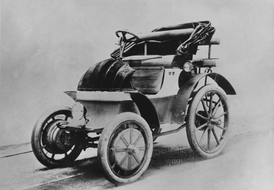
Figure 1.1 The early 1900's Lohner-Porsche, the first hybrid vehicle on record. Source: Reproduced by permission of Porsche Cars North America, Inc.
In 1904, Henry Ford developed the first assembly line manufacturing plant for gas-powered vehicles. As the twentieth century progressed, the automotive industry began to develop rapidly, and motor vehicles were soon available in steam, electric, and gasoline versions. While gas-powered vehicles are prevalent in our world today, electric vehicles (EVs) were more popular than other vehicle alternatives in the early 1900s. The primary reason for its popularity at this time was functionality. Unlike gasoline vehicles, electric vehicles were without the engine-related vibration, smell, and noise. However, gasoline vehicles require manual gear shifting, which was regarded as a difficult component of driving at the time. Likewise, EVs were also preferable to steam-powered vehicles because they were capable of longer ranges on a single charge, and were more convenient during colder weather. Under similar weather conditions, steam-powered vehicles suffered from start-up times of up to 45 minutes.
The electric vehicles continued to be attractive until the 1920s, with peak production occurring in 1912. However, improvements in intercity road quality propelled the need for ICE vehicles, which were capable of operating at longer distances. At the same time, the discovery of oil reduced the price of gasoline, making internal combustion vehicles more affordable to consumers. Moreover, the invention of the electric starter made the use of the internal combustion vehicles more convenient, whereas the long recharge time of electric vehicles and the expensive large battery packs made the electric vehicles less attractive to consumers. As a result of these developments, the market for EVs gradually disappeared by the 1930s.
Moving forward in time, cars became less of a luxury and more of a necessity for everyday life. While the increased use and development of internal combustion vehicles have changed city landscapes and lifestyles, scientists began to worry about the long-term environmental effects of ICE exhaust emissions. Most concerns related to the influence of vehicle emissions on the onset of global warming and excessive greenhouse gas production. Furthermore, oil prices began to rise around this time, along with increased public awareness of the limited supply of oil resources. This led to a pressing need for alternatively-powered vehicles, which began to surface in the 1970s.
The afore-mentioned issues also led governments to take several legislative and regulatory actions to moderate oil production dependency and reduce the causes of air pollution. Likewise, several organizations from around the world began to work with vehicle manufacturers to create conditions more favorable to the development of electric vehicles. As a result of these changes, the automotive industry began to renew their attempts to develop electric vehicles.
In 1974, the American company, Sebring-Vanguard, designed the CitiCar, the first mass-produced electric car, and continued its production until 1977. From 1977–1979, General Motors Company spent over $20 million in electric car development and research, with a stated objective to produce electric vehicles by the mid-1980s. Similarly, Peugeot and Renault designed an electric vehicle that could drive at 100 km/h, with a travel range of 140 km. In 1989, Audi unveiled the first generation of the experimental Audi Duo, a petrol engine/electric hybrid concept vehicle. This car had rear wheels driven by a 12.6 hp electric engine, and front-wheel drive powered by a 2.3 litre 5-cylinder engine with a 136 hp output. In 1996, General Motors designed and developed an electric motor vehicle called the EV1, which had a top speed of 130 km/h and a range of 130 km.
Improvements in electric vehicle performance motivated the automotive industry to develop and market mass-produced electric vehicles. However, the electric vehicle market could not achieve success with consumers, and was largely failing by the end of the 1990s. The primary reason for the failure of EVs was their limited performance capability as compared to gasoline-powered vehicles. Moreover, the low price of oil at the time, as well as the EVs' high initial costs, high maintenance costs, and infrastructure shortage contributed to their commercial lack of success.
However, a new type of motorization appeared in the late 1990s: hybrid technology, which combined the internal combustion engine with an electric motor. Toyota made the Prius, the first mass-produced hybrid electric vehicle (HEV), which was launched successfully in Japan in 1997. Shortly after, in 1999, the Honda Insight was launched in both the United States and Japan. These two vehicles pioneered the hybrid vehicle concept, and led to a shift in the market perception of alternative fuel vehicles.
Since then, other car manufacturers have designed and produced a variety of fuel-efficient vehicles using vehicle electrification technology. Ford introduced its first hybrid vehicle in 2004 with the Escape SUV hybrid model. Likewise, General Motors introduced the Silverado and the Sierra in 2004 as their first hybrid vehicle models. Currently, countries such as Brazil and China are competing to increase their shares in the worldwide market of EVs and HEVs.
Nevertheless, the share of HEVs worldwide is still quite low when compared to IC engine vehicles. In 2004, the share of HEVs was 0.25% whereas in 2007, the total production of 541 000 HEVs was only 0.8% of the production of light vehicles worldwide. Anticipated production numbers of HEVs predict an increase to 1.7 million by 2014. The increasing share of HEVs overall reflects the accelerating pace towards greater electrification of vehicles, and eventually, the production of zero emission vehicles with better efficiency [6].
1.2 Internal Combustion Engine Vehicles (ICEVs)
Most modern vehicles create propulsion power through an internal combustion engine. An internal combustion engine generates propulsion power from the combustion of fuel and an oxidizer in a confined cylindrical space known as a combustion chamber. The engine then takes the heat energy generated by the combustion process and converts it into mechanical work based on the principle of energy conservation.
The oxidizer of an IC engine is typically oxygen, which is sufficiently available in the Earth's atmosphere. The most common fuels used in an IC engine are gasoline and diesel; however, other fuels such as hydrogen, methane, and propane are also used. The exothermic reaction of the fuel with the oxidizer results in the production of high-temperature and high-pressure gases. The expansion of these gases applies force to a piston inside the combustion chamber. Subsequently, the linear motion of the piston is transferred to the wheels through the crankshaft and the vehicle transmission system. The advantageous features of IC engines are a high power-to-weight ratio and excellent fuel energy density.
Dutch physicist Christian Huygens first proposed the design concept of a working internal combustion engine in 1680. Almost 130 years later, Swiss engineer François Isaac de Rivaz realized Huygens' vision by inventing an unsuccessful version of the IC engine. His internal combustion engine attempted to propel automobiles by burning a fuel mixture of hydrogen and oxygen for power. While de Rivaz's attempts failed to achieve success, the efforts of English engineer Samuel Brown were successful. In 1826, Brown developed a hydrogen-fueled combustion engine that was industry-compatible. Brown's engine had separate combustion and working cylinders with four hp.
The first functioning and successfully designed gas-powered internal combustion engine was invented in 1860 by Jean Joseph Etienne Lenoir. Fueled by coal gas, this engine was a double-acting, electric spark-ignition capable of running continuously. In 1863, Lenoir further improved this engine model so that it was able to run on petroleum using a primitive carburetor. Following these developments, engineers continued to invent and modify variations of the IC engine. However, the most significant contribution was the invention of the four-stroke engine by Nicolaus August Otto in 1876. The patented “Otto Cycle Engine,” a universally implemented, practical four-stroke IC engine was soon in all liquid-fueled automobiles. A four-stroke engine still powers most modern cars and trucks.
In 1885, German engineers and design partners, Gottlieb Daimler and Wilhelm Maybach modified the Otto Cycle Engine by reducing its size while increasing its speed and efficiency. Their engine was small, lightweight, and quick; it used a gasoline-injected carburetor and had a vertical cylinder. In 1886, as a separate work and without any knowledge of Daimler's and Maybach's work, German engineer Karl Benz patented the first gas-fueled automobile powered by a four-stroke engine. Benz's engine designs were the pioneers for modern vehicles. Rudolph Diesel made another key contribution towards improving the efficiency of IC engines by inventing and patenting the diesel engine in 1892.
Currently, gasoline and diesel engines are the main power sources for the majority of road vehicles. Most cars and light-duty vehicles use gasoline engines while heavy-duty vehicles, buses, and some passenger cars use diesel. Diesel engines are more fuel-efficient and more powerful at lower speeds than gasoline engines. However, they are also noisier, heavier, and more difficult to start in cold weather conditions. While gasoline engines have an easier time starting in the cold, they are still prone to problems under extreme conditions.
Both gasoline and diesel engines convert the chemical energy of fuel into motion through a four-stroke process, and are available as either reciprocating or piston engines. A reciprocating engine includes a number of cylinders (combustion chambers), each containing a piston that moves up and down. Each piston connects to the crankshaft (Figure 1.2) through a connecting rod, which rotates the crankshaft by using the reciprocating (up-and-down) motions of the piston. The crankshaft features offset axis sections called crankpins. While the upper end of the connecting rod attaches to the piston with a joint, the bearing offset sections attach to the end of the connecting rod. The design of the crankshaft causes the reciprocating motion of the pistons to translate into a rotary motion. In manual transmissions, the rotary motion of the crankshaft transfers to the drivetrain through the flywheel; in automatic transmissions, the motion transfers through a torque convertor.
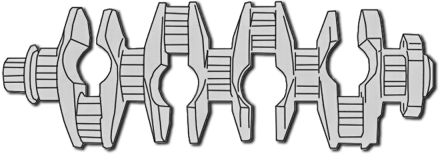
Figure 1.2 A vehicle engine's crankshaft
The cycles of engines with more than one cylinder are arranged evenly for smooth operation. The number of cylinders used in an engine varies, based on engine performance and specification. Generally, engines with 4–8 cylinders power vehicles; however, higher performance vehicles may have up to 16 cylinders, while some small cars or motorcycles use engines with only 1 or 2 cylinders. Engines with more cylinders provide a higher engine capacity for the vehicle. Engine capacity or engine displacement is the total cylinder volume swept by all of the pistons in a single movement. Increasing the diameter of the piston and lengthening the stroke increases engine capacity. Engines with greater capacities can achieve greater power and torque at the cost of increased fuel consumption. Higher numbers of cylinders make it possible to use smaller and lighter cylinders for a given fuel mass, resulting in a smoother engine operation. However, increased cylinder numbers result in a heavier mass and more internal friction between pistons and cylinders. This may adversely affect the overall efficiency and performance of the vehicle engine.
Turning on an engine requires an electric starter motor to rotate the crankshaft. The rotary motion of the crankshaft causes some of the connecting rods to push the pistons upward, thereby compressing the mixture of fuel and air. The combustion propels the engine to start working, and as long as the vehicle moves, the inertia of the crankshaft causes the pistons to move up and down inside the cylinders [7].
1.2.1 The Four-Stroke Gasoline Engine
A gasoline internal combustion engine converts the chemical energy of fuel to mechanical energy through a process called the four-stroke cycle. This process is also known as the Otto cycle in honor of its inventor, Nikolaus Otto. Each four-stroke cycle makes two engine revolutions. Cylinders, pistons, valves, and spark plugs are the primary components of the engine during the combustion process. As illustrated in Figure 1.3, the four-stroke process includes the intake stroke, compression stroke, power stroke, and exhaust stroke as described below:
- Intake stroke: This is the first stroke of the cycle. Initially, the intake valve opens and the piston is at the top of the cylinder. The piston subsequently slides down the cylinder to create a low-pressure environment. While the outlet (exhaust) valve remains closed, the low-pressure environment draws a measured volume of fuel and air mixture inside the cylinder. When the piston reaches the bottom of the stroke (to the maximum volume position), the intake valve closes and this stroke ends.
- Compression stroke: While both the intake and outlet valves are closed, the piston starts moving upwards and squeezes the air–fuel mixture from the top of the cylinder. The stroke finishes when the piston reaches the minimum volume position. The air–fuel compression results in an increase in pressure, temperature, and fuel mixture density.
- Power stroke: Once the piston reaches its maximum compression ratio (the top of the cylinder), the compressed air–fuel mixture ignites with a spark plug. This stage generates lots of heat, and the resulting high temperature and pressure gases push the piston downward. The intake and outlet valves remain closed during this stroke. Gasoline engines, occasionally referred to as SI engines, use the spark ignition (SI) system. The SI system is an electrical system that includes a lead-acid battery and an induction coil. The system provides a high-voltage electric spark to ignite the air–fuel mixture inside the cylinder. The battery is recharged on-board using an alternator driven by the engine.
- Exhaust stroke: This is the fourth and final stroke of the cycle. The leftover combustion by-products and gases in the power stroke, called the exhaust, are vacated during the exhaust stroke. Once the piston reaches the bottom of the cylinder at the end of the power stroke, the outlet (exhaust) valve opens and the exhaust stroke begins. The crankshaft pushes the piston upwards to expel the exhaust from the cylinder through the outlet valve. At the end of this stroke, the exhaust valve closes. As the exhaust valve closes, the intake valve opens and the sequence cycle repeats.

Figure 1.3 The gasoline (Otto) engine cycle
1.2.2 The Four-Stroke Diesel Engine
Like the gasoline engine, the diesel engine is also a four-stroke engine, though it operates slightly differently. Rather than a spark ignition system, diesel engines use a compression heating ignition system in which the ignition of the air–fuel mixture occurs because of compression instead of a spark plug. In other words, ignition occurs when the diesel fuel is sprayed into the cylinder filled with compressed air.
When compared to gasoline engines, additional advantages of the diesel engine include its superior fuel economy, higher compression ratio, and enhanced durability. The desirable fuel economy is a result of its properties, high compression ratio, and lower fuel price. The higher compression ratio produces better thermal efficiency, consequently resulting in highly effective mechanical work. Diesel fuel is also cheaper than gasoline when measured in fuel volume. Moreover, despite both fuel types having similar amounts of energy in specified weights, the amount of energy in a specific volume of diesel fuel is still 10% greater than that of gasoline. However, the high compression ratio of a diesel engine results in very high pressure, which consequently produces a high level of stress on engine materials. Furthermore, diesel engine components such as cylinders, pistons, rods, and valves are much heavier and thicker, which causes the diesel engine to be sluggish. Another issue with the diesel engine is its complicated fuel injector system. Since diesel fuel does not evaporate easily, high-pressure injection nozzles are required to produce the appropriate air–fuel mixture. As illustrated in Figure 1.4, the four-strokes of the diesel cycle are intake stroke, compression stroke, power stroke, and exhaust stroke as described below:
- Intake stroke: The intake valve opens and draws air in the cylinder while the piston slides downward. The intake valve closes when the piston reaches the maximum volume.
- Compression stroke: The piston pushes upwards and compresses the air to about 1/16th of its initial volume. Air temperature can reach up to 1000 °C in this stage.
- Power stroke: Diesel fuel enters the cylinder by the fuel injector just before the peak of compression. The air–fuel mixture starts burning due to the high pressure and temperature within the combustion chamber, and the resulting thermodynamic energy pushes the piston down. Throughout the course of this stage, both intake and exhaust valves remain closed.
- Exhaust stroke: The exhaust valve opens and the piston slides upwards while the combustion gases emits through the exhaust valve. Once the piston reaches the head of the cylinder, the exhaust valve closes and the intake valve opens, restarting the cycle.
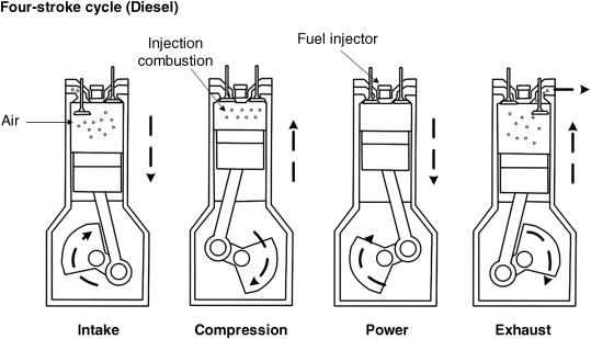
Figure 1.4 The diesel engine cycle
1.2.3 ICE Performance Characteristics
An established performance baseline evaluates and compares several parameters and variables of IC engines (ICEs). Assessing and comparing efficiencies is a method of evaluating the performance of an engine. This includes aspects such as fuel efficiency, thermal efficiency, work efficiency, and engine emissions, among others. The following subsection discusses the most significant parameters, including power-to-weight ratio, air-to-fuel ratio, power-to-volume ratio, and volumetric efficiency.
1.2.3.1 Power-to-Weight Ratio
Power-to-weight ratio is the engine's power output to the weight of the vehicle; it evaluates engine performance, regardless of vehicle size. Generally, a power-to-weight ratio value is a compromise between comfort, fuel economy, and emissions. Since engine power is a function of its speed, the power-to-weight ratio varies based on the speed range of the vehicle. When the vehicle is at a standstill, the ratio is at zero; it rises when the vehicle accelerates. The ratio reaches its peak value as speed increases, and begins declining as the speed continues to rise.
Power-to-weight ratio has a direct relation to the maximum acceleration of a vehicle. Essentially, a greater power-to-weight ratio directs a vehicle to accelerate faster than a vehicle with a lower ratio. For example, consider two vehicles that have the same engines but different power-to-weight ratios. If additional conditions such as energy loss amounts are identical, the vehicle with the greater ratio is always faster. As such, decreasing the weight of vehicles with higher levels of power can result in enhanced fuel economy and reduced emissions. Diesel vehicles generally have a smaller power-to-weight ratio in comparison to gasoline vehicles. This is because diesel vehicles require a heavier engine (and additional components) to resist the operating pressure caused by the high compression ratio.
1.2.3.2 Air–Fuel Ratio
Both gasoline and diesel fuels are a composition of hydrocarbons (made from hydrogen, oxygen and carbon). They react with the oxygen available in the air to kindle burning. In an internal combustion engine, the air (oxygen) available in the cylinder can burn a portion of fuel. If the amount of fuel is greater than the air available (rich fuel mixture), some unburned fuel will remain after combustion occurs. The vehicle expels the unburned fuel into the environment through the exhaust valves and tailpipe, consequently polluting the air and environment. On the other hand, if the amount of air is more than the amount of fuel (lean fuel mixture), there will be more oxygen available in the exhaust gases produced. Note, in a gasoline engine, lean fuel mixtures may cause engine knocking, an abnormal combustion in which the remaining air–fuel mixture in the chamber detonates due to high-pressure and heat. Engine knocking produces aggravating noises, reduces engine efficiency, and may damage engine materials. Additionally, a lean air–fuel mixture may also generate more nitrogen–oxide pollutants. Ultimately, the engine performance is a function of the direct relationship between an engine's air flow and its fuel requirements.
In engine design, the definition of air–fuel ratio is a measure of the air–fuel mixture quality. This ratio measures the weight ratio between air and fuel in the air–fuel mixture within a combustion chamber at any given moment. A desirable air–fuel ratio is one that allows the engine to achieve maximum power and the best fuel economy while producing the least emissions. However, these objectives are conflicting since the fuel requirements of an engine change, based on variations in temperature, load, and speed conditions.
The stoichiometric air–fuel ratio is an air–fuel mixture with a certain weight of air that oxidizes available fuel without leaving behind excess oxygen or unburned fuel. This ratio is 14.7 for gasoline engines and 14.5 for diesel engines. A mixture that is less than a stoichiometric ratio is a rich mixture, while a mixture greater than a stoichiometric ratio is a lean mixture. Gasoline engines need lean mixtures to attain optimal fuel economy through minimum fuel consumption while they need rich mixtures to suppress combustion knock and to attain maximum power (Figure 1.5). Idle heavy loads and high-speed conditions require a rich mixture and normal cruising and light load conditions require a lean mixture. The air–fuel ratio needed to start an engine is approximately 9, and the best possible fuel economy is attainable with an air–fuel ratio of 16. Acceleration, idling, and full power requirements need an air–fuel ratio of approximately 12.
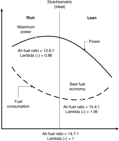
Figure 1.5 Effects of air–fuel ratio variation on the fuel economy and power generation of a gasoline engine
The throttle and fuel injector regulate the air–fuel ratio in a gasoline engine vehicle. The throttle is a valve that varies the engine airflow, while the electronic fuel injector sprays a measured amount of fuel into the cylinder. The function of the throttle is to adjust the amount of air entering the intake manifold. The vehicle driver controls this mechanism through the throttle (accelerator) pedal.
Older vehicles (pre-1990) used a carburetor to mix air and fuel. A carburetor is a mechanical device that regulates the amount of fuel drawn into the airstream based on the speed and pressure of airflow entering the engine. Fuel injection systems replaced carburetors and they are no longer used in production vehicles due to their lower fuel efficiency and higher emission rates.
In modern vehicles, the Engine Control Unit (ECU) determines the amount of fuel that the injector sprays into the intake manifold. The ECU calculates this amount based on information obtained from sensors installed within the vehicle. Oxygen, mass airflow, throttle position, and coolant temperature sensors send the most significant data. The exhaust pipe houses the oxygen sensor, which detects rich and lean mixtures by monitoring the amount of available oxygen. The throttle position sensor monitors the throttle pedal position. The mass airflow sensor measures the air mass entering the intake manifold. The coolant temperature sensor measures the engine temperature to determine if it has reached the appropriate operating conditions. When the driver steps on the throttle pedal to demand more power from the engine, the mass airflow sensor sends the ECU information about the amount of air mass entering the engine. The ECU subsequently injects more fuel into the intake manifold based on this information. Likewise, the ECU also acquires temperature data from the coolant temperature sensor. If the engine has not reached proper working temperature, the ECU accordingly injects more fuel to help heat up the engine. In cruise and light load conditions, the ECU keeps the air–fuel ratio close to stoichiometric proportions based on the amount of oxygen leaving the exhaust pipe, as measured by the oxygen sensor. On the other hand, high speed/high load conditions require a proper rich air–fuel mixture. In these circumstances, the injector feeds a measured amount of fuel regardless of the information given by the sensors. This variation is necessary to ensure a higher margin against detonation.
With some exceptions, diesel engines generally draw an uncontrolled amount of air into the cylinders because they do not have a throttle valve or throttled system. Regulating the amount of fuel injected at the end of a compression stroke controls the speed and power. Unlike gasoline engines, which can run on rich, lean, and stoichiometric fuel mixtures, diesel engines mostly run on a lean mixture. The combustion temperature of lean fuel mixtures is lower than that of stoichiometric mixtures because it burns less fuel. Lower temperature environments lessen the amount of heat lost in the engine, allowing more heat energy to convert into mechanical work by pistons during combustion.
1.2.3.3 Power-to-Volume Ratio
The power-to-volume (compression) ratio is the ratio between the generated power and volume of air–fuel mixture at the beginning and end of the compression stroke. Essentially, the compression ratio represents the compressibility of the air–fuel mixture within the cylinder of a vehicle engine. This fundamental specification is important when evaluating the performance of an engine. Generally, a higher compression ratio is more desirable because it provides the vehicle with greater power and increases engine efficiency. As such, an engine with a higher compression ratio generates more mechanical energy for a specific mass of air–fuel mixture. Moreover, a high compression ratio may also indicate that the fuel can burn completely, thus reducing the exhaustion of by-products. A disadvantage of increasing the compression ratio is that the engine becomes more prone to engine knocking. However, a lean air–fuel mixture, gasoline with lower octane ratings (poor quality), and knock sensor malfunctions can also trigger this phenomenon.
1.2.3.4 Volumetric Efficiency
In most reciprocating engines, the air–fuel mixture is drawn into the combustion chamber during the intake stroke due to low-pressure environment that is created by the downward motion of the piston. The amount of air inhaled by the engine is usually less than the theoretical amount of air that an engine can receive under atmospheric pressure due to factors such as intake system components, cycle time limitations, friction losses, and leaks. The amount of air that can be drawn to an engine is important since for a specific air–fuel ratio, higher amounts of inhaled air means more fuel can be combusted and consequently more energy can be converted to the output power.
Volumetric efficiency measures the effectiveness of an engine's intake process and provides a ratio of the amount of air–fuel drawn in the combustion chamber and the theoretical maximum. The theoretical maximum is the actual capacity of the combustion chamber under static conditions. Higher volumetric efficiency of an engine results in an increase in engine speed and overall power. The volumetric efficiency of an engine is affected by parameters such as the compression ratio, fuel type, air–fuel ratio, engine speed, air–fuel mixture temperature, and the pressure ratio of exhaust to intake manifold. Moreover, volumetric efficiency can be enhanced through the use of larger valves, multiple valves, variable valve timing, and force induction systems such as supercharging or turbocharging. Larger valves pull in a greater amount of airflow at the expense of heavier weight while multi-valve engines take advantage of two or more smaller valves at the expense of higher complexity.
1.2.4 ICE Vehicle Emissions
Vehicle emissions are one of the key contributors to environmental air pollution and global climate change. Tank-to-wheel and well-to-wheel emissions are the most common ways to discuss motor vehicle emissions. Tank-to-wheel refers to emissions produced during vehicle operation and during fuel combustion. On the other hand, well-to-wheel emission refers to discharges during the production and distribution of fuel, as well as throughout vehicle operation. The subsequent section discusses tank-to-wheel emissions and their effects on the global environment.
As mentioned earlier in this chapter, IC engines generate propulsion power by combusting air and a fuel, usually gasoline or diesel, within a combustion chamber. Gasoline and diesel fuels are a mixture of hydrocarbons (made of hydrogen, oxygen and carbon atoms), while air is mainly composed of nitrogen (N2) and oxygen (O2). In a perfectly operating engine with ideal combustion conditions, hydrocarbons would react with oxygen to produce water vapor (H2O) and carbon dioxide (CO2), while nitrogen would pass through the engine unaffected. However, depending on the operating conditions and the fuel-air ratio, an incomplete combustion procedure may occur, causing the vehicle to emit pollutants as well.
The amount of pollution that a vehicle emits depends on many factors. The most important factors include fuel rate consumption, driving conditions (e.g., the speed, acceleration, and load on the vehicle), the type of fuel used (e.g., gasoline or diesel), and the technology used to control emissions (e.g., catalysts), among others.
The main emissions from vehicles are carbon dioxide (CO2), carbon monoxide (CO), hydrocarbons (HC), particulate matters (PM), nitrogen oxides (NOx), nitrous oxide (N2O), and methane (CH4). The reaction of oxygen with existing sulfur and carbon fuel impurities can also result in sulfur monoxides (SO) and sulfur dioxide (SO2) emissions, which contribute to acid rain formation. Vehicle emissions belong to two categories: greenhouse gas emissions and air pollution emissions. Greenhouse gas emissions contribute to climate change, particularly global warming, whereas the term air pollution emission refers to harmful smog-forming pollutants released by vehicles. Carbon dioxide, nitrous oxide, and methane are greenhouse gas emissions, whereas hydrocarbons, particulate matters, nitrogen oxides, sulfur monoxides, and sulfur dioxide are air pollution emissions [8–15].
1.2.4.1 Greenhouse Gas Emissions
Greenhouse gases trap heat in the atmosphere by absorbing and emitting radiation within the thermal infrared range. This process is the fundamental cause of the greenhouse effect. However, the high concentration level of these gases contributes to climate change – particularly global warming.
Global warming is a term used to describe increases in the average atmospheric temperature near the Earth's surface, as well as in the troposphere, both of which contribute to changes in global climate patterns. The most significant consequences of global warming are melting glaciers, rising sea levels, flooding, gully erosion, desertification, and extreme weather conditions. Although there are a variety of natural sources that emit greenhouse gases, scientists have observed elevated levels of these gases in recent decades, especially in regards to carbon dioxide and methane. This increase is widely attributed to vehicle emissions and other human activities that involve burning fossil fuels. The primary greenhouse gases in the Earth's atmosphere include carbon dioxide (CO2), methane (CH4), nitrous oxide (NOx), and water vapor (H2O).
- Carbon dioxide: During the combustion process, hydrocarbons in fuel react with oxygen in the air to create water vapor and carbon dioxide. Even if perfect combustion were to occur, the sheer volume of vehicles worldwide would still release astonishing amounts of CO2. Carbon dioxide is the principal greenhouse gas warming the Earth. Vehicles are the second largest source of carbon dioxide emissions (coal-burning power plants are first), generating nearly 1.5 billion tons of carbon dioxide annually.
- Nitrous oxides: Nitrous oxides are a product of the reaction that occurs between nitrogen and oxygen during fossil fuel combustion. Nitrous oxides are approximately 130 times more effective in trapping atmospheric heat than carbon dioxide over a hundred-year period. Though fuel nitrogen content produces nitrous oxides, the primary source of this emission is the pollution control device (catalytic converter) used in modern vehicles. The amount of emissions released by a vehicle largely depends on its fuel type, technology, and maintenance and operating points. For example, a catalytic converter – the device used to remove pollutants from the vehicle exhaust – can potentially promote the formation of N2O. The highest volume of emissions occurs when the catalyst is not fully functional and when exhaust gases are at low temperatures. Drive cycle, vehicle speed, and catalyst age are also contributory factors to the production of nitrous oxides emissions.
- Methane: Methane emissions occur because of incomplete fuel combustion. The primary factors that affect the volume of methane emissions are the emission control system, fuel type, engine design and tuning, and vehicle age. Additionally, methane emission increases at lower ambient temperatures because liquid fuel does not completely vaporize (and thus, burn) at lower temperatures. Methane emission is at its lowest when the catalyst is fully functional, and when exhaust gases are at their hottest.
1.2.4.2 Air Pollution Emissions
Air pollution has become a major environmental concern because of the continual worldwide increase in automobile production. Currently, vehicle-induced air pollution has reached startling levels in both developed and developing countries. Health authorities have confirmed that harmful air pollutants can cause a variety of lung-related illnesses such as asthma, emphysema, and bronchitis, while also increasing the risk of cancer. The following emissions are involved in air pollution:
- Carbon monoxide: Carbon monoxide (CO) forms during rich fuel mixture combustion due to a lack of sufficient oxygen. Specifically, the combination of carbon atoms in a hydrocarbon fuel with one oxygen atom, rather than two, forms this emission. Chemical kinetic effects also result in the production of small amounts of carbon monoxide under lean conditions. CO is colorless, odorless, highly poisonous, and extremely detrimental to human health. Vehicles emit high volumes of CO when the air–fuel ratios within the engine are too rich. This tends to occur as soon as the vehicle starts because the engine is not yet at optimal operating conditions. Additionally, carbon monoxide emissions increase at higher altitudes because the amount of oxygen in the air is not sufficient for perfect combustion. Other factors that increase these emissions include leaky injectors, high fuel pressure, and improperly closed-loop catalyst controls. Transportation sources such as cars and trucks are the primary contributors of carbon monoxide, exceeding 90% of total CO emissions in certain locations (e.g., urban areas).
- Hydrocarbons: Hydrocarbons are another major vehicle emission. During incomplete combustion, some fuel molecules remain unburned or partially burned and are exhausted into the atmosphere. The reaction of exhausted hydrocarbons with other compounds in the atmosphere produces ground-level ozone, a key component of smog. Hydrocarbons are toxic and, with prolonged exposure, can cause a variety of human illnesses such as liver disease, lung disease, and cancer. The main factors that contribute to high amounts of hydrocarbon emissions are improper ignition timing, improper air–fuel ratio, and low air temperature levels. Additional reasons for excessive hydrocarbon emissions include malfunctions with ignition components, air injection components, and catalytic converters. Fuel evaporation during refueling and crevice volumes (such as the space between the piston and cylinder wall) can also result in hydrocarbons being emitted into the air.
- Particulate matter: Vehicle exhaust contains a mixture of small solid particles and liquid droplets. This mixture is particulate matter and it forms during combustion, as well as after carbon-containing molecules condense into their solid form. Pollutants found in particulate matter vary in size and include substances such as carbon, sulfur, and nitrogen compound metals. Vehicles emit particulate matter referred to as fine particulate matter or PM2.5 because of their 2.5-μm diameter. These pollutants are small enough to travel deep into the lungs of humans and can adversely affect the heart. Diesel engines produce much higher rates of particulate matter pollutants than gasoline engines.
- Nitrogen oxides: During combustion, high temperatures and pressures inside the combustion chamber may result in a reaction between nitrogen and oxygen in the air. This reaction results in the production of nitrogen oxides, including nitric oxide (NO) and nitrogen dioxide (NO2). Moderate and heavy load conditions usually result in peak production of these emissions due to the high level of combustion pressures and temperatures that occur under these circumstances. However, light operating conditions such as cruise or light throttle operations may also produce small amounts of nitrogen oxides. Nitrogen dioxide causes a variety of health and environmental concerns, specifically in regards to ozone and smog. Nitrogen oxide emissions become part of particulate matter formation through chemical reactions in the atmosphere.
1.2.4.3 Idling Emissions
Vehicle idling is perhaps the most significant factor in generating air pollutants and wasting natural resources. In addition to these concerns, idling can also cause damage to the engine. When idling, the fuel is below peak temperatures, resulting in incomplete combustion and fuel residue build-up on cylinder walls and spark plugs. Consequently, this build-up can significantly diminish the efficiency of an engine. Furthermore, idling and its associated consequences pose a significant health risk to humans. Drivers and passengers inside idling vehicles are subject to concentrated exposure of pollution because there is no airflow available to dissipate it. Children are even more vulnerable under these circumstances because they breathe faster and inhale a higher ratio of air in comparison to their body weight.
In addition to traffic jams, the main causes for idling in both diesel and gasoline vehicles are individual habits and a general misunderstanding of engine functionality. Some of the reasons for individuals to intentionally idle the engine include: using it as a means to keep the engine warm during cold weather, attempting to maintain adequate battery voltage for the use of electrical devices, and using the air-conditioner or heater for personal comfort. A common misconception is that engine idling should be used to warm up the vehicle prior to driving in cold weather. In reality, the most effective way to heat up the engine is simply by driving the vehicle. The catalytic converter cannot operate below certain temperatures and will function better when the vehicle is moving. Idling also causes the vehicle to release higher levels of emissions. Driving the vehicle quickly after starting the engine while avoiding significant acceleration or high speeds during the first few kilometers is more effective in heating up an engine. This will ensure that the vehicle reaches optimal operational temperatures with minimum amount of fuel.
1.2.4.4 Gasoline Engine Emissions vs. Diesel Engine Emissions
The majority of emissions from diesel-fueled vehicles are particulate matter, nitrogen oxides, and hydrocarbons, whereas gasoline-fueled vehicles release mostly carbon monoxide, hydrocarbons, and nitrogen oxides. The amount of emissions released by a vehicle depends on a number of factors, including operation conditions, environment, and engine temperatures, fuel quality, and most importantly, air–fuel ratio. Figures 1.6 and 1.7 illustrate the effect of air–fuel ratio variations on gasoline and diesel vehicle emissions. In these figures, λ represents a normalized ratio based on the proportion of air–fuel ratio and stoichiometric air–fuel ratio. As illustrated in Figure 1.6, the amount of emissions produced under lean mixtures is less than the amount produced by rich mixtures in a gasoline engine. However, lean mixtures can cause engine knocking and reduce engine power. Furthermore, lean mixtures generate high amounts of nitrogen oxide emissions when they have an air–fuel ratio near stoichiometric proportions. This is because a stoichiometric ratio produces the high temperature gases necessary to form nitrogen oxide. As such, the designs of gasoline engines need to meet the conflicting requirements necessary for efficiency, power, and emissions. As Figure 1.7 illustrates, diesel engines have greater amounts of hydrocarbons and particulate matter at high air–fuel ratios (lean mixtures). This occurs because after combustion, the heat generated by lean mixtures is not high enough to burn out residual hydrocarbons. The burning of low air–fuel ratios (rich mixtures) in a diesel engine increases particulate matter emissions because it lacks the oxygen necessary for oxidation. A common problem with gasoline and diesel engines is that reducing nitrogen oxide emissions results in the increase of hydrocarbon emissions.
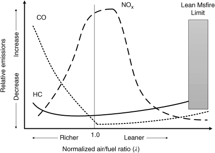
Figure 1.6 Effect of air–fuel ratio on gasoline vehicle emissions

Figure 1.7 Effect of air–fuel ratio on gasoline vehicle emissions
1.3 Vehicle Emission Control Technologies
The advances in engine design, air–fuel mixture preparation, and proper ignition timing can considerably reduce emissions in modern ICE vehicles. However, these advances often do not meet increasingly stringent emission policies and regulations. An obstacle towards further improving the release of vehicle emissions is the conflicting specifications of engine complexity, fuel efficiency, power, and emission requirements. As such, emission control technologies are important in normalizing engine emissions to standard levels without jeopardizing vehicle and engine performance.
Emission control systems are designed to reduce the amount of air pollution emitted by a vehicle. Types of tank-to-wheel emissions of ICE vehicles are tailpipe exhaust emissions, evaporative emissions, and crankcase emissions. Tailpipe exhaust emissions refer to emissions that are expelled into the air through the exhaust pipe. These emissions usually contain hydrocarbons, carbon monoxide, nitrogen oxide, and particulate matter. Evaporative emissions refer to fuel vapors that escape into the air through the fuel tank or during refueling. Likewise, crankcase emissions are unburned or partially burned fuels vented to the engine compartment.
Gasoline and diesel engines use several technologies to control emissions, with the most important ones being catalytic converters, exhaust gas recirculation, crankcase emission control, and evaporate emission control. While the structures may differ, the main functions of these control technologies are similar for both engine types [16–21].
1.3.1 Advanced Engine Design
Emissions from an ICE can be reduced by improving the engine design and controlling the combustion process. Engine design should be optimized for efficiency and performance under a variety of driving conditions, while minimizing its emissions. Properly controlling the engine and combustion process variables such as ignition timing, air–fuel ratio, the volumetric efficiency, and the compression ratio can also significantly reduce the level of engine emissions. Advanced control technologies such as fuel injection systems, electronic engine units, controlled air induction systems, variable valve timing, and turbocharging systems have been shown to be effective in reducing emissions of both diesel and gasoline vehicles. Generally, the most important of these are variable valve timing and turbocharging systems. The subsequent section discusses these two technologies in detail.
1.3.1.1 Variable Valve Timing
“Valve timing” is the time interval within which a valve is open, while the time interval in which the intake and exhaust valves simultaneously open is called a “valve overlap time” or “timing of breathing.” Proper controls of valve timing and valve overlaps play an important role in reducing engine emissions, improving engine fuel economy, and enhancing the output power. For example, a slight delay in the closing of the intake valve pushes some air–fuel mixture back into the intake manifold by the piston during the compression stroke. This action subsequently increases the intake manifold pressure and results in a richer air–fuel mixture during the next cycle. What this sequence of events means is that delayed intake valve closing results in better fuel economy and lower nitrogen oxide emissions during partial load conditions. However, these benefits come at the expense of a slight loss in peak engine torque. In contrast, closing the intake valve earlier during normal combustion circumstances produces lower pressure within the cylinder during the compression stroke. Consequently, this reduces the amount of work required from the piston. The early intake valve closing also produces better fuel economy and lower nitrogen–oxide emissions. However, closing the intake valve earlier also increases hydrocarbon emissions due to low temperatures caused by low-pressure conditions. Another disadvantage of prematurely closing the intake valve is the reduction in engine performance at high-speed conditions. Engine performance suffers under these circumstances because the intake valve closes before the maximum amount of air–fuel mixture enters the cylinder.
In general, reductions in overlap result in a smoother idle and more slow-speed torque, while increases in overlap produce more power and better engine breathing. However, the disadvantages of more overlap include rough idling and high exhaust emissions. Most conventional vehicles use an engine with fixed valve events, in which valves open and close at fixed times during engine strokes, independent of engine load and speed conditions. The flexibility of variation in valve events that are subject to speed and load conditions allows the engine to operate more efficiently over its operating range and conditions.
The design of variable valve timing aims to improve engine performance by controlling the timing of valves through different operating modes. This technology makes it possible to control the stream flow of intake and exhaust gases coming into and out of the combustion chamber with variable valve events. It also allows the engine to achieve optimal power and torque across a wider range of engine speeds with lower emissions. In diesel engines, the combination of variable valve timing and exhaust gas recirculation can significantly reduce the hydrocarbon and nitrogen–oxide emissions. However, this reduction comes at the expense of an increased amount of particulate matter in the exhaust.
1.3.1.2 Turbocharging Systems
The primary function of a turbocharger is to increase the amount of oxygen inhaled into the combustion chamber by compressing the air intake. This compression results in enhanced volumetric efficiency, reduced particulate matter and hydrocarbon emissions, and improvements in fuel efficiency. However, due to the increase in combustion pressure, turbochargers can also increase the rate of nitrogen–oxide emissions. A turbocharger is composed of a turbine, a compressor, and a center housing/hub rotating assembly (see Figure 1.8). Hot exhaust gases drive the turbine and they leave the engine through the exhaust ports. The captured kinetic energy of the exhaust gases drives the compressor through a shaft in the turbo housing. The blades of the compressor draw ambient air inside and accelerate it back into the engine. Before the intake air enters the intake manifold, the compressor increases its mass, compresses it, and increases its pressure.
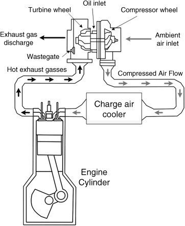
Figure 1.8 A schematic of a turbocharging system
Turbochargers are capable of providing volumetric efficiency greater than 100% because in these engine types, the intake manifold pressure exceeds atmospheric pressure. However, the engine efficiency comes at the expense of reduced power from the cylinders. This reduction occurs because the turbine in the exhaust causes the exhaust stroke of the engine to push harder against higher backpressure. The two major problems of turbochargers are turbo lag and high intake air temperature. Turbo lag is a sluggish (delayed) response from the engine during the initial push on the throttle pedal. It occurs due to the initial inertia of the turbocharger. Essentially, at low engine speeds, the exhaust gas flow is not strong enough to push the turbine quickly. The compression of the intake air results in increased air pressure, which in turn causes the temperature to rise. Excessive intake air temperature and pressure may cause detonation (engine knocking) or pre-ignition phenomena, which reduces the output power. Pre-ignition is an abnormal combustion in which high pressure and temperature cause the air–fuel mixture to ignite earlier than it would by spark plug fire. To cool down the intake air, an intercooler located in the middle of the piping between the turbocharger's compressor and the engine's air intake valve is integrated. The waste-gate usually regulates and limits air intake pressure. The waste-gate controls air pressure by bypassing some of the exhaust gas flow before entering the turbine as it reaches the intake pressure threshold.
An advanced type of turbocharger technology is the variable turbine geometry turbocharger, also known as a variable geometry turbocharger or a variable nozzle turbine. This type of turbocharger contains a set of adjustable vanes in the turbine housing. These vanes are modified in angle throughout the engine speed to maximize and control boost pressure over a wide range of engine operations. The vanes guide the exhaust flow towards the turbine while an actuator adjusts their angles. The purpose of a variable geometry turbocharger is to partially close the vanes at low-speed conditions. Partially closing these vanes directs exhaust gas towards the turbine and pushes the turbine blades to the right angle. This will cause the turbine to spin faster before the engine reaches proper speed. At higher speeds where the exhaust flow is sufficiently strong, the vanes open completely to capture the high kinetic energy of the exhaust gas. This reduces the exhaust pressure in the turbocharger by removing the waste-gate from the circuit.
A variable geometry turbocharger reduces turbo lag at low engine speeds, provides cleaner exhaust gas, and improves fuel economy while maintaining power and performance. Furthermore, these turbochargers also effectively reduce particulate matter emissions from diesel engines by providing lean combustion in the engine. Diesel engine vehicles mainly use variable geometry turbochargers; they have achieved some success with gasoline engine vehicles as well. The high temperature of exhaust gases is the main obstruction preventing complete integration of variable geometry turbochargers within gasoline engines.
1.3.2 Catalytic Converters
Positioned in the exhaust pipe, catalytic converters are emission control devices that convert unsafe exhaust emissions into harmless compounds through a combination of catalysts. A catalyst is a chemical material that increases the rate of a chemical reaction without changing itself in the process. Platinum, rhodium, and palladium are the most commonly used catalysts.
The catalytic converter plays a significant role in vehicle emission reduction, which is why it is the main emission control technology used in vehicles. However, leaded fuels adversely affect the efficiency of catalytic convertors. These fuels form deposits that coat the catalyst and prevent proper contact between exhaust gasses and catalysts. The catalytic converters used in gasoline vehicles include oxidation (two-way) catalysts and oxidation–reduction (three-way) catalysts, while diesel vehicles use diesel oxidation catalysts, selective catalytic reduction, and nitrogen–oxide adsorber catalysts. Important factors that affect the performance of a catalytic converter are catalyst temperatures, mixture air–fuel ratio, and hydrocarbon mix.
1.3.2.1 The Two-Way Catalyst
Two-way catalysts use an oxidation process to convert carbon monoxide and hydrocarbons to carbon dioxide and water. Vehicles used the oxidation catalyst from the mid-1970s until the 1980s, but the invention of the three-way catalyst has rendered it obsolete in modern vehicles.
1.3.2.2 The Three-Way Catalyst
Almost all modern vehicles have three-way catalysts. They convert nitrogen oxide back into nitrogen and oxygen, and convert carbon monoxide and hydrocarbons into water and carbon dioxide. When the air–fuel ratio is close to stoichiometric, it is possible to achieve the maximum conversion efficiency for all three pollutants. In these circumstances, three-way catalysts are capable of oxidizing hydrocarbons and carbon monoxide while reducing nitrogen–oxide emissions. A fuel-ratio range between 0.98 and 1.003 can achieve a high conversion efficiency. However, this range is quite narrow and limiting. For leaner mixtures, the efficiency of the catalyst in conversion of hydrocarbons and monoxide increases, however, the catalyst is inefficient at reducing nitrogen–oxide emission. In contrast, for richer mixtures, the conversion efficiency of nitrogen–oxide emissions increases while the efficiency of carbon monoxide and hydrocarbons decreases.
An ECU helps keep a three-way catalyst at its optimal operation conditions, which greatly depends on the catalytic temperature. In other words, high conversion efficiency can be achieved if the catalytic temperature reaches a certain value known as “light off temperature,” which is usually in the range of 200 °C–300 °C. By contrast, the efficiency of catalysts can decrease because of overheated conditions, which can occur due to improper engine tuning, inadequate rich air–fuel mixtures, or cylinder misfiring.
1.3.2.3 Diesel Oxidation Catalyst (DOC)
The lean combustion of diesel engines prevents the use of three-way catalysts. As such, most diesel engines use a diesel oxidation catalyst (DOC), which converts carbon monoxides and hydrocarbons to carbon dioxide and water through an oxidation process, while also reducing soot mass. However, DOCs are inefficient in reducing nitrogen oxides and particulate matter. Additionally, they are capable of oxidizing sulfur dioxide that exists in diesel exhaust (specifically in heavy-duty vehicles). The oxidation of sulfur dioxide forms sulfate particles, which in turn increase the amount of total particle emissions. As such, DOCs need to be designed in a way that balances a sufficient reduction of hydrocarbons and carbon monoxides with reasonable amounts of sulfur-dioxide. The efficiency of catalysts can be improved if they are used in conjunction with other emission control technologies. The effect of DOCs on fuel consumption is not substantial. Light-duty diesel vehicles frequently use DOCs, although they have been shown to be effective in heavy-duty vehicles as well.
1.3.2.4 Selective Catalytic Reduction (SCR)
Selective catalytic reduction (SCR) is one of the most efficient emission control technologies. SCR helps to reduce nitrogen oxide emissions to near zero levels through a catalytic reaction while also providing good fuel economy and durability. It is possible to apply SCR to all types of diesel-powered vehicles (light, medium, heavy-duty) without compromising engine power and performance. SCR functions by injecting diesel exhaust fluid (DEF), a liquid containing urea and water, into the exhaust stream, which is just ahead of the SCR converter. Urea is a nitrogen compound that hydrolyses into ammonia (NH3) when heated. In the presence of a catalyst, the ammonia reacts with the exhaust stream to produce nitrogen and water vapor. However, some un-reacted ammonia may be released into the atmosphere as well. This is known as an “ammonia slip” and can be caused by over-injected DEF in the gas stream, low temperature conditions, or a degraded catalyst.
A highly controlled system regulates the amount of injected DEF, it adequately distributes the ammonia in the gas stream and provides a consistent gas velocity for the catalyst. The control system works either as an open-loop or closed-loop system. The open-loop system uses a nitrogen oxide estimation algorithm to estimate the amount of nitrogen oxide available in the exhaust stream. The algorithm uses operation conditions such as engine speed, exhaust temperature, and load to determine the amount of DEF to inject. The closed-loop system obtains data through a sensor that measures nitrogen oxide concentration; from this it calculates the amount of DEF to inject. A concern during the conversion process of this catalyst is the possible formation of sulfate. As such, it is important to use low sulfur fuel to avoid further particulate emissions and to enhance the catalyst efficiency. A disadvantage of the SCR system is its dependency on a tank to store DEF liquid, if the tank runs dry, the SCR system stops functioning.
1.3.2.5 Nitrogen–Oxide (NOx) Adsorber Catalyst
As opposed to gasoline engines, diesel engines usually run at lean fuel mixture conditions. However, recently, the design of lean-burn gasoline engines suits passenger vehicles as well. A lean-burn gasoline engine provides a higher compression ratio, better performance, superior fuel efficiency, and lower carbon monoxide emissions than that of conventional gasoline engines. These benefits, however, come at the expense of higher production of nitrogen–oxide emissions. These emissions occur as a result of the increased levels of oxygen in the fuel mixture and exhaust gases. Since a conventional three-way catalyst does not effectively reduce nitrogen oxides under lean conditions, the mass production of such vehicles has been a subject of great debate.
A NOx adsorber (known as a lean NOx trap or LNT) is a catalyst designed to reduce nitrogen–oxide emissions; it is most effective in lean-burn engines. An LNT system stores nitrogen–oxide emissions in a catalyst under lean conditions. It then catalytically reduces the trapped nitrogen oxide to nitrogen when the engine is running under rich conditions. The cycle in which a catalytic reaction between excess unburned hydrocarbons and nitrogen oxide converts the trapped nitrogen oxide to nitrogen is called the nitrogen–oxide regeneration cycle. The operating temperature, system responsiveness, and diesel sulfur content are the main factors affecting the catalyst efficiency. Like other catalysts, LNT offers superior performance at higher operating temperatures and lower sulfur fuels. The main advantages of LNT technology include high efficiency in nitrogen oxide emission reduction, low light-off temperature, and a cost-effective system. However, LNT adversely affects vehicle fuel economy because of the fuel requirements and burn conditions of the nitrogen oxide regeneration cycle. While the effectiveness of LNT under stoichiometric conditions is less than that of three-way catalysts, it still provides significant benefits under lean conditions.
1.3.3 The Diesel Particulate Filter (DPF)
A diesel particulate filter (DPF) collects and removes diesel particulate matters or soot from the exhaust of the engine by passing exhaust gases through the walls between numerous channels (see Figure 1.9). A DPF accumulates soot and particulate matters over time; however, since filters have limited capacity, they need to be removed or cleaned in order to avoid backpressure blockage on the engine. If left dirty, this blockage may result in engine damage or destruction.
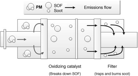
Figure 1.9 A schematic of a passive diesel particulate filter
Some filters are designed for single use and can easily be discarded or replaced. For other filters, it is necessary to remove the accumulated particulate matters. A practical approach to dispose of the trapped materials is to burn or oxidize the particulate matters within the filter once the exhaust gases reach a certain temperature. The process of cleaning by burning the trapped materials is called filter regeneration.
A passively regenerated filter is a filter regenerated by available exhaust heat or by using a catalyst. On the other hand, an actively regenerated filter is one that uses active means during the filter regeneration process. For example, actively regenerated filters can either use the injection of diesel fuel into an upstream of DOC, or utilize a fuel burner that heats the filter to particulate matters combustion temperatures. Passive regeneration cannot be used if the exhaust temperature is lower than the threshold, whereas in active regeneration techniques, it is possible to integrate various engine controls to provide filter regeneration conditions on demand. Integrating a combination of passive and active strategies can ensure the completion of filter regeneration under all possible vehicle operating conditions. Additionally, reduction in particulate matters and nitrogen oxide emissions can be simultaneously achieved if a diesel particulate filter is used in conjunction with exhaust gas recirculation, nitrogen–oxide adsorber catalysts, or selective catalytic reduction.
1.3.4 Exhaust Gas Recirculation (EGR)
Figure 1.10 depicts a schematic of an exhaust gas recirculation (EGR) for a gasoline engine. This technology reduces nitrogen oxide emissions in both gasoline and diesel engines during operating periods in which high combustion temperatures occur. The principal function of an EGR is to recirculate a controlled portion of exhaust gases into the engine combustion chamber through a valve. This technology recirculates some exhaust gases to the intake manifold where the temperature of recirculated exhaust gases usually decreases by passing gases through an intercooler. The recirculated exhaust gases subsequently mix with the incoming intake manifold air, resulting in a diluted air–fuel mixture. This dilution causes a lower heat release and a lower peak cylinder temperature, which subsequently reduces nitrogen oxide formation. The recirculated exhaust gases must mix homogeneously with incoming air to have a consistent EGR distribution per cylinder. Improper EGR distribution may cause one cylinder to receive higher amounts of EGR, resulting in a higher rate of particulate matters emissions. Conversely, cylinders receiving low amounts of EGR produce higher rates of nitrogen oxide emissions. The EGR system prolongs the engine life because it reduces the peak of combustion temperature.
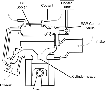
Figure 1.10 Schematic of the EGR loop for a gasoline engine
In a gasoline engine, an EGR system provides different types of exhaust gas flow. For example, EGR systems use a high flow of exhaust gases during operating conditions with high combustion temperatures, such as cruising and mid-range acceleration. Likewise, it provides a low flow of gases during low speed or light load conditions. The EGR system stops recirculating gases at full power demands as the recirculation process reduces engine operating efficiency, and also during idling to avoid higher level of emissions.
It is important to precisely regulate the amount of recirculated exhaust gases. This amount is a trade-off between a reduction in nitrogen oxide emissions and engine efficiency. Excessive recirculation of exhaust gases degrades the engine performance and efficiency, while minimal recirculation results in engine knocking and a decrease in EGR efficiency. Modern vehicles utilize ECU, sensors, and servo-driven EGR valves to balance engine efficiency and vehicle drivability by regulating the recirculation flow rate.
In diesel engines, reducing nitrogen–oxide emission occurs at the cost of an increase in particulate matters' emissions. The two main types of EGR systems used by diesel engines include high pressure loop EGR and low-pressure loop EGR (Figure 1.11). A high-pressure loop EGR diverts the exhaust gases before they reach the turbocharger turbine section. Conversely, the low-pressure loop EGR captures the exhaust gases after passing through the turbocharger and the diesel particulate filter. Incorporating a diesel particulate filter or an oxidation catalyst in an EGR loop helps reduce the amount of particulate matters re-routed to the combustion process.
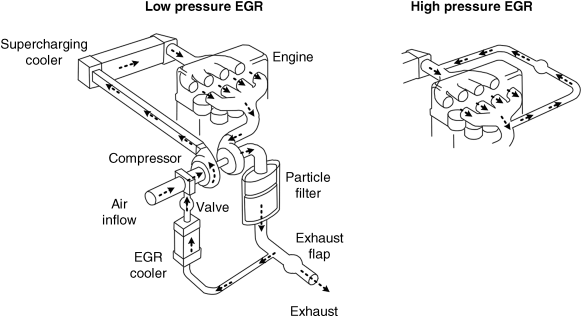
Figure 1.11 The EGR loop for a diesel engine
Integrating a combination of high- and low-pressure loop systems with a variable geometry turbocharger can enhance the EGR system efficiency over a wide range of operating conditions. The low-pressure EGR recirculates exhaust gases at low engine speeds and loads, while high-pressure EGR functions under higher engine speeds and loads. An optimized combination of the technologies will provide a more effective and efficient reduction of nitrogen oxide.
1.3.5 Crankcase Emission Control System
Blow-by gases are gases that leak into the crankcase during power or compression strokes while an engine is running. They are composed of mostly unburnt or partially burnt hydrocarbons and combustion by-products, which leak through the clearances between the piston rings and the cylinder walls.
The ventilation of blow-by gases helps prevent pressure build-up and increases engine longevity. In uncontrolled crankcase emission, a road draft tube releases blow-by gases and other vapors directly into the atmosphere. Hydrocarbon and particulate matters emissions are the classifications of these gases, and, if they enter the cabin, can be a significant source of emission exposure for drivers and passengers.
The crankcase emission control system, shown in Figure 1.12, is designed to re-burn the blow-by gases by diverting them into the intake system of a gasoline or diesel engine. When a gasoline engine vehicle is moving, fresh air flows to the crankcase through an air inlet path called the breather. The incoming air transfers and recirculates the blow-by gases from the crankcase into the intake system, allowing it to mix with an incoming stream of air.
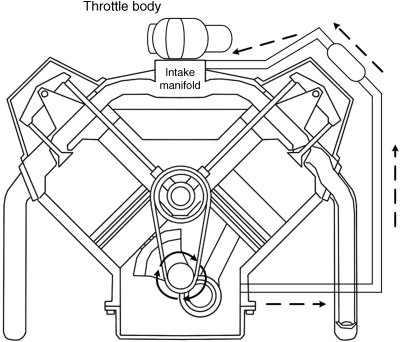
Figure 1.12 Crankcase emission control system of a gasoline engine
A check valve adjusts the gas flow between the crankcase and the intake manifold; the positive crankcase ventilation (PCV) valve controls the intake system pressure of the check valve. Then the diverted mix of air and blow-gases is injected into the combustion chamber where it is re-burned. Valve malfunctions may result in the blockage of blow-by gases and since the gases are under pressure, they may find other ways to escape from the crankcase to other parts of the engine compartment. These malfunctions can cause damage to engine parts, and result in oil leaks and sludge formation within the engine.
In a diesel engine, a multi-stage filter collects and returns the emitted lube oil to the engine's sump. Then, filtered gases reroute with a balanced differential pressure to the intake system. The crankcase emission control system of diesel vehicles often includes filter housing, a pressure regulator, a pressure relief valve, and an oil check valve.
1.4 Vehicles with Alternative Fuels
Although control emission technologies cost-effectively reduce internal combustion engine emissions, a narrow range of operating conditions limit their maximum efficiency. Furthermore, malfunctioning or improper tuning can dramatically degrade their performance or even result in increased vehicle emissions.
The development of vehicles operating with cleaner alternative fuels has received increasingly greater attention from industries and governments in the twenty-first century. Alternative fuels have the potential to reduce fossil fuel dependency and reduce pollutant emissions. Unfortunately, the cost of such vehicles or their operating costs are significantly higher than that of conventional gasoline/diesel vehicles in many countries. Nevertheless, vehicles powered with alternative fuels are more cost-effective and economical in some territories. The economic benefits of these fuel types largely depend on fuel consumption and government policies such as fuel tax and fuel price. The most significant types of alternative fuels used in vehicles include natural gas, liquid petroleum gas (propane and butane), biodiesel, and hydrogen.
1.4.1 Natural Gas Vehicles (NGVs)
As a clean-burning alternative to diesel/gasoline fuel, natural gas is a combustible mixture of hydrocarbon gases. It primarily consists of methane (approximately 80%), but also includes lesser amounts of propane, ethane, and butane. It is possible to use it in vehicles in the form of Compressed Natural Gas (CNG) or, less commonly, Liquefied Natural Gas (LNG). Light and medium-duty vehicles generally use CNG, whereas heavy-duty vehicles use LNG.
Dedicated, retrofitted, bi-fuel, and dual-fuel engines are all possible designs for a natural gas vehicle (NGV). Both dedicated and retrofitted engines operate merely on natural gas fuel. A bi-fuel engine runs on either natural gas or gasoline while a dual-fuel engine functions on a combination of natural gas and diesel fuel. A retrofitted engine is an engine modified from an engine designed for gasoline vehicles, while dedicated engines are those engines specifically designed and optimized to run on natural gas. Bi-fuel vehicles use two tanks to store fuels separately, allowing the engine to run on one fuel at a time. Conversely, dual-fuel vehicles burn a blend of two fuels stored in a single tank. In comparison with dedicated and dual-fuel vehicles, bi-fuel vehicles offer fuel flexibility at the expense of passenger/cargo space. Dedicated and bi-fuel engines are spark-ignited while dual-fuel engines need a diesel igniter to operate. The air-gas mixture in the cylinder of dual-fuel engines ignites with the injection of a small amount of diesel fuel, which self-ignites. Natural gas vehicles produce significantly lower nitrogen oxides, particulate matters, and carbon dioxide emissions than conventional gasoline/diesel vehicles because of their low carbon content and high compression ratio.
Since the air mixture in the combustion chamber of a NGV is completely gaseous, the emissions associated with cold start ignitions do not exist. However, because the main constituent of natural gas is methane, these vehicles emit considerably more methane than gasoline and diesel vehicles. The stoichiometric ratio of CNG is 17.2, higher than that of diesel and gasoline fuels. Gasoline or diesel engines retrofitted to operate on CNG may not provide the amount of emission benefits as a dedicated engine. Burning LPG in an engine optimized for gasoline/diesel fuel stoichiometric conditions will result in a rich-fuel condition.
Economically, CNG is usually cheaper than gasoline due to the more stable market and abundance of resources. The Energy Protection Agency (EPA) in the United States selected the Honda Civic GX – designed as a dedicated CNG vehicle – for eight years till 2012 as the cleanest-burning combustion engine vehicle. Although most major automotive industries offered vehicle models powered by CNG, the Honda Civic GX is the most commercialized CNG vehicle currently available in the global market.
Despite its advantages, the market for NGVs is very narrow because of its limitations in design technology, fuel infrastructure, and driving range. The primary issue is onboard fuel storage. Currently, CNG is stored in a high-pressure cylinder, and LNG is stored in an insulated tank. Both storage systems are considerably heavier, more expensive, and bulkier than storage systems for equivalent amounts of gasoline or diesel, thereby reducing the vehicle's power-to-weight ratio. Furthermore, NGVs require frequent refueling in comparison to their gasoline and diesel counterparts for similar travel distances due to lower volume energy density of natural gas in comparison with gasoline and diesel. The performance of these vehicles is comparable to gasoline and diesel vehicles when the CNG tank is under full pressure. However, when the pressure falls below a certain threshold, NGVs display limited performance at high speeds and uphill settings. Another important obstacle preventing the widespread commercialization of NGVs is the lack of refueling infrastructure for natural gas. Moreover, the use of gas storage cylinders that have limited shape flexibility is inconvenient for vehicle designers. Despite clean performance and abundant resources, NGVs still run on unsustainable fuel resources.
Due to economic factors, most NGVs use retrofitted engines. Unfortunately, the performance of retrofitted engines is not optimal compared to dedicated engines that are designed with the express aim of operating with natural gas fuels. In addition, as a result of extremely limited access to CNG refueling stations, most retrofitted NGVs are bi-fuel. Currently, fleet vehicles such as taxi cabs, transit vehicles, and school buses are the main applications of natural gas-fueled technologies.
1.4.2 Liquefied Petroleum Gas Vehicles (LPGVs)
As a by-product of natural gas and refined crude oil, liquefied petroleum gas (LPG) is composed of propane and butane. This fuel is also known as propane and autogas, and is currently the most prevalent alternative fuel. LPG is a fuel for conventional vehicles while producing lower levels of toxic and smog-forming air pollutants compared to fossil fuels.
The engine technologies behind LPG-fueled vehicles are similar to those of NGVs. The design of an LPG engine can be as a dedicated or bi-fuel engine, though it is possible to convert conventional combustion engines to use LPG as well. However, the use of LPG in dual-fuel diesel engines is uncommon due to its poor knock resistance.
Converting a gasoline or diesel engine to operate with LPG is cheaper than converting it to operate with natural gas because of lower fuel tank costs. Another advantage to CNG is the convenience of carrying LPG onboard the vehicle. The principal function of a LPG engine is similar to that of a spark-ignition engine. Like natural gas, LPG can function with a higher compression ratio, which results in increased power output and reduced exhaust emissions. LPG engines generate lower amounts of emissions under cold start conditions and perform better in low-speed and light-throttle conditions as well. This is because LPG injects into the combustion chamber as a vapor and the air mixture within the chamber is completely gaseous. The power output and torque of LPG engines are similar to gasoline engines. As such, LPG-driven vehicles can perform comparably to gasoline vehicles in terms of climbing slopes and traveling in mountainous areas.
Unlike gasoline engine vehicles, LPGVs produce near-zero particulate emissions, very little carbon monoxide, and only moderate amounts of hydrocarbons. Additionally, the carbon monoxide emissions of LPG vehicles are typically lower as well, while nitrogen oxide emissions are similar to the amount released from gasoline vehicles. LPGVs produce much higher levels of carbon monoxide and hydrocarbon emissions compared to NGVs. Like CNG, LPG has a stoichiometric ratio (A/F = 15.7) higher than that of gasoline/diesel fuel. As such, a retrofitted LPG engine may not be as efficient as a dedicated engine in terms of emission benefits.
Toyota made the first LPG vehicles in the 1970s. Despite the advantages of LPG-vehicles, they have a limited share of vehicles on the road. Like NGVs, the main obstacles preventing widespread commercialization of LPG-equipped vehicles are driving range, vehicle fuel availability, and infrastructure. The current LPG vehicles suffer from limiting vehicle space due to the additional tank required for the LPG fuel. With a similar volume of fuel, LPG vehicles travel shorter distances compared to diesel and gasoline vehicles due to the lower volumetric energy density of LPG, making it necessary for the vehicle to refuel frequently. Moreover, LPG is also a by-product of substances with limited resources. Additionally, despite producing lower level of emissions compared to gasoline/diesel-fueled vehicles, LPG vehicles still produce pollutants that affect air quality. Using a three-way catalyst or an oxidation catalyst in conjunction with an LPG engine further reduces the emission level.
1.4.3 Biodiesel
Biodiesel is a natural alternative fuel for compression-ignition (diesel) engines that can be derived from a variety of renewable biological energy sources, including vegetable oil, animal fat, and cooking oil. Biodiesel is the result of a chemical process known as trans-esterification. This process involves extraction of the basic compounds of biodiesel such as esters from natural oil resources through a catalytic chemical reaction with methanol. Currently, the primary feed stocks used in the production of biodiesel fuels are soybeans, canola oil, and yellow grease. Biodiesel fuel or their blends in most diesel engines work with little to no modification to the engine. Usually, the concentration of biodiesel in fuel blends is denoted by a system known as the “B” factor. For example, the denotation of 100% (pure) biodiesel is B100 while a diesel fuel with 20% biodiesel and 80% petro-diesel is known as B20.
The expected use of biodiesel in pure or blended form reduces carbon dioxide, particulate matters, and hydrocarbon emissions of diesel engines, in addition to slightly increasing nitrogen–oxide emissions. These actions occur because of the oxygen available in biodiesel, which allows the fuel to burn more completely. Moreover, nitrogen–oxide emission control technologies can eliminate or significantly reduce the nitrogen oxide emissions that the combustion of these fuels emits. In addition to reducing emissions, biodiesel fuel offers other important advantages compared to fossil fuels. Some of these benefits include: renewability (significantly beneficial for the environment), limited sulfur–dioxide production (can directly reduce the formation of acid rain), safer disposal of extraneous fuel (biodiesel fuel is non-toxic and degrades faster than petroleum diesel fuel), and better lubricant properties (biodiesel fuel is a very effective lubricant and acts very much like a solvent, capable of cleaning the engine).
Despite these benefits, biodiesel fuel still has a number of disadvantages. The main problem is a conflict with the engine warranty policies of major auto manufacturers, who have not yet accepted the use of blends more concentrated than B5. This lack of legal policy restricts the widespread use of biodiesel fuel. Additionally, biodiesel is more expensive to purchase on a recurring basis. They have lower energy content and fuel economy than fossil fuels – approximately 10% lower for B100 and 2% lower for B20 blends. The B100 blend raises further concerns due to its potentially adverse impact on engine durability over prolonged periods of usage, as well as its suitability for lower temperatures.
1.4.4 Hydrogen
Hydrogen is an alternative fuel for vehicle propulsion when burnt in an internal combustion engine using the combustion of a mixture of hydrogen and air. Hydrogen fuel is a decarbonized energy carrier that does not naturally occur in pure form. Hydrogen can be obtained mainly either by converting combustible molecules into hydrogen or by consuming electric energy. The common methods used to produce hydrogen include water electrolysis, natural gas reformation, or partial oxidation and steam reformation of other fossil fuels. Hydrogen production is available domestically from renewable sources such as wind, solar, and nuclear. Currently, natural gas most often functions to generate hydrogen. While there are environmental consequences of producing hydrogen from reformed fossil fuels, studies comparing the well-to-wheel emissions of hydrogen and petroleum productions have shown overall reductions in ozone and GHG while using hydrogen. However, an even more distinct advantage would be to use renewable energy to generate hydrogen. Hydrogen is appealing because it can reduce or eliminate carbon dioxide emissions from vehicular propulsion systems by deprecating the use of fossil fuels. Regardless of the amount of emissions released from the formation of hydrogen, hydrogen-fueled ICE vehicles can potentially have near-zero tailpipe emissions. The only harmful emission released from these vehicles would be nitrogen–oxide emissions, which occur because of the high temperature from hydrogen oxidation during the combustion process. Integrating nitrogen–oxide emission control technologies is the most convenient way to reduce this type of emission in hydrogen vehicles.
Since a hydrogen-fueled engine burns fuel similarly to conventional gasoline engines, a slight modification to a gasoline-based internal combustion engine can create a hydrogen-fueled engine. François Isaac de Rivaz designed the first hydrogen engine in 1807. However, it was not until 1970 that Paul Dieges added a patented modification to Rivaz's design. This modification allowed the engine to run using hydrogen, and eliminated much of the negative environmental effects. Modified internal combustion engines (e.g., Mazda's Wankel engine) are a low-cost and viable alternative technology. A number of automakers, including BMW, Mazda, and Ford, have separately launched production-bound hydrogen ICE vehicles. Some critics assert that hydrogen is not an ideal fuel solution for ICE engines because it increases the propensity for pre-ignition. However, certain experiments by auto-makers have completely dismissed these concerns. Currently, there are even suggestions for a gradual withdrawal from conventional fossil fuels to make way for complete reliance on hydrogen fuels.
A major concern regarding the use of hydrogen as a fuel is its storage. The most common ways to carry hydrogen on a vehicle includes storing it as a compressed gas, liquid, or in the form of metal hybrids by using chemical storage. Reforming liquid fuel sources such as methanol, ethanol, natural gas, and liquid petroleum gas can produce hydrogen on-board a vehicle. However, doing so requires a process to convert the existing liquid fuel sources into hydrogen. These requirements increase the overall cost while also adding maintenance costs to the system. Moreover, reforming fuel sources also releases carbon dioxide. Nevertheless, the amount of emissions released by engines operating on reformed fuel is much less than that of gasoline-powered engines. However, the volumetric energy density of compressed hydrogen gas is also much smaller than that of gasoline. As a result, hydrogen-powered vehicles have shorter traveling distances and less torque output.
Compressed hydrogen requires a heavier chassis and greater amount of space to hold equivalent amounts of gasoline. This increases the weight of the vehicle, resulting in a lower power-to-weight ratio. However, with the same fuel mass, this engine can run at higher efficiency levels than a gasoline combustion engine. This increased efficiency is a result of the higher compression and leaner air–fuel ratios of hydrogen fuel. In general, the issues associated with hydrogen engines are production, distribution, storage, and refueling. While sustained research and development efforts are bringing hydrogen-powered vehicles closer to widespread commercialization, the development of these vehicles is still in its early stages. The increased usage of hydrogen vehicles can substantially reduce fossil fuel dependency.
1.5 Powertrain Technologies
The powertrain system of a vehicle converts one or multiple forms of energy to mechanical energy that is used in vehicle wheels for propulsion. The efficiency, function, and design of vehicle powertrains are crucial in the vehicle's fuel consumption, emission release, comfort, and weight. The powertrain of a conventional vehicle includes the engine, transmission, and drivetrain. The engine generates mechanical power by burning fuel that is transmitted to the drivetrain through the transmission. The transmission system adjusts the speed and torque output of the engine through a variety of gears and shafts, while the drivetrain transfers the adjusted torque and speed to the wheels through the differential, axle, and driveshaft. The powertrain components and subsystems need to be designed and optimized to provide superior vehicle performance, driving comfort, fuel economy, emission reduction, and minimal noises. There are various powertrain configurations, for example, it is possible to mount the engine at the front or rear of the vehicle. With the exception of some light vehicles and buses, most vehicle types employ a front-mounted engine. The powertrain also determines which wheels are driven on a vehicle, with options such as: rear-wheel drive, front-wheel drive, or multi-wheel drive [22–28].
1.5.1 Rear-Wheel Drive Powertrains
Figure 1.13 illustrates a rear-wheel drive powertrain in which the engine power transfers to the rear wheels through the transmission, drive (propeller) shaft, differential, and axle. The front of the vehicle contains the engine, while the transmission is behind the engine. Usually, the engine and transmission are in alignment with longitudinal installation. This type of system provides a good catalytic converter configuration because of its long exhaust system. It also provides more space for the engine, making it more suitable for powerful vehicles. The proper weight distribution that occurs in a rear-wheel drive system results in greater vehicle handling and performance ability. Additionally, the load transfer to the back of the vehicle allows this system to provide better traction on the driven wheels during heavy acceleration. The driveshaft and other components needed to transfer the power to rear wheels result in reduced fuel economy and engine power. Furthermore, the additional weight of these components also increases the weight-to-power ratio of the vehicle. Luxury and racing vehicles usually have rear-wheel drive integration.

Figure 1.13 Rear-wheel drive powertrain configuration
1.5.2 Front-Wheel Drive (FWD) Powertrains
As Figure 1.14 shows, in a front-wheel drive (FWD) powertrain, the engine and transmission system are at the front of the vehicle. As such, the engine power transfers directly to the front wheels through the transaxle. The transaxle consolidates the transmission, differential, and the associated components of the driven axle in one unit.
Figure 1.14 Front-wheel drive transverse powertrain configuration
The front-wheel drive arrangement provides better fuel economy and less engine power loss than rear-wheel drive because it contains less moving components. During heavy acceleration, traction loss may occur due to load transfer towards the back of the vehicle. However, FWD vehicles as they deliver the load on steered and driven wheels, have improved road-holding and traction. Moreover, this arrangement provides more space for the cargo and passenger cabin at the expense of reduced space for the engine and other front-located components (e.g., steering mechanism, engine compartments).
There are two types of FWD powertrain systems, transverse or longitudinal, depending on how the vehicle's engine and transmission are mounted. In transverse powertrains, the engine and transmission are mounted parallel to the front axle. Conversely, in the longitudinal powertrain, the engine and transmission are parallel to the longitudinal vehicle axis. The integration of each system also depends on the engine and transmission size, as well as the available space. The transverse front-wheel drive powertrain is found in the majority of modern small and mid-sized vehicles.
1.5.3 Multi-Wheel Drive Powertrains
A multi-wheel drive powertrain delivers the engine torque to all four wheels of the vehicle. In some configurations, the torque transmits to both axles when all the wheels are continuously driven. In other configurations, the engine power transmits to one of the two axles, while another axle can engage manually or automatically when needed. In a multi wheel-drive, the engine torque transfers to the axles through a power-split differential system such as a center differential, transfer case, or another type of gear set. In this power-split system, the torque of each axle routes to the wheels on each side through each axle differential.
Multi-wheel drive systems are further available as four-wheel drive and all-wheel drive (AWD) systems. In four-wheel drive systems, the power-split differential may contain one or more sets of low-range gears with the ability to select two-wheel drive or four-wheel drive operation. The low-range gears reduce the vehicle speed in order to increase the torque routed to the axles. This helps when driving in extreme off-road conditions or on rough terrain. Conversely, the power-split differential of all-wheel drive systems does not include the low-range gears, and it does not offer a manual switch from four-wheel drive to two-wheel drive. Generally, multi-wheel drive systems provide better traction on all road conditions, better acceleration in low gear, and better handling performance. However, these advantages come at the expense of a very complex powertrain system and reduced fuel economy. Figure 1.15 illustrates a schematic of a multi-wheel drive powertrain configuration.
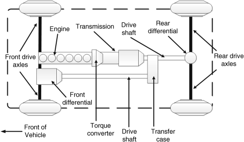
Figure 1.15 Multi-wheel drive powertrain configuration
There are also other less common powertrain configurations that vehicles can use, such as a rear-mounted engine rear-wheel drive, or a rear-mounted engine four-wheel drive. These configurations are rare in modern vehicles because they make the vehicle prone to instability, particularly during cornering.
1.6 Transmission Systems
A transmission system manages the output torque and power of the engine and sends it to the drive wheels through a number of gears or drive-ratios. This system connects to the engine through a flywheel, a heavy disk used to make the rotational output speed of the engine uniform. The engine only provides a limited range of torques and speeds, which is insufficient for some working conditions such as starting, stopping, acceleration, or deceleration. Essentially, the engine provides speed and torque up to a certain value, while the wheel road speeds and moving torque amount vary, based on driving and load conditions. For example, a high torque and low speed are required to move a vehicle from a stop knowing that the engine cannot provide the required torques at low speed conditions. In this case, the transmission system increases the level of torque delivered to the drive wheels by reducing the engine speed to match the lower wheel speed torque requirements. In contrast, high-speed cruise conditions require much less torque to move the vehicle. In this setting, the engine power and torque are directly transmitted to the drive wheels through the transmission system while holding the high speed of the engine's. Additionally, a transmission system also provides positional options for the vehicle to be in neutral, to reverse, or to park. The neutral position allows the driver to disengage the engine from the drive wheels, while the reverse position allows the vehicle to move backwards. The park position locks the driveshaft to prevent the vehicle from rolling. Some of the transmission types used in modern vehicles include: manual, automatic, semi-automatic, and continuously variable transmissions.
1.6.1 Manual Transmission/Transaxle Systems
The manual transmission system is the first type of transmission that was integrated into a vehicle while the manual transaxle system developed many years later with the introduction of front-wheel drive vehicles. Manual transmission systems and manual transaxle systems adjust the engine power and speed through a set of gears that can be shifted manually by a driver through a clutch pedal and shift knob. Typically, manual transmissions are used in powertrains in which the engine and drive wheels are located on two ends of the vehicle (e.g., front-mounted engine rear-wheel drive or four-wheel drive systems). Likewise, manual transaxle systems are used in powertrains in which the engine and drive-wheels are located on the same vehicle end (e.g., front-mounted engine front-wheel drive). These systems are similar in many ways – they both function to efficiently transfer engine torque to the drive wheels. The primary difference between the two is that a transaxle system transfers engine torque while also providing the differential action to the drive wheels, whereas the differential for a manual transmission system is separate and is connected to the transmission through the driveshaft. The mistakenly interchangeable use of the terms transmission and transaxle is common. The main components of a manual transmission/transaxle include the clutch, the gears, the shafts, and the synchronized collars:
- The clutch: The clutch is a coupling device with the primary function of engaging or disengaging the engine from the transmission system, as necessary. It regulates torque transfer from the engine to the gears, and makes gear shifting easier and smoother. The driver typically operates the clutch by using a foot pedal.
- The gears: Gears are a major component of the manual transmission/transaxle system. They are mounted on two separate shafts, and mesh with one another by sliding in and out of engagement. Gears with different sizes and different numbers of teeth mesh together in order to change the engine torque and speed by transmitting the rotating motion from one shaft to another. The gears provide functionalities such as magnifying the engine torque while reducing engine speed or vice versa, transferring the torque while keeping the engine speed, or changing the torque direction. Driving gears and driven gears are the two types of gears on a manual transmission/transaxle system. The driving gears receive their rotation from input shaft. In manual transmissions, the driven gears transfer the rotation to the output shaft, whereas in manual transaxles, this rotation transfers to the differential. The gear ratio reflects the ratio of the input and output torques of a transmission system. The gear ratio is a function of the number of teeth meshing on the driving and driven gears, as well as their rotational velocities. Most modern transmission/transaxle systems have at least four forward gear ratios. Higher gear ratios belonging to the first and second gears provide higher torque and lower speed to the drive wheel, while lower gear ratios belonging to the third and fourth gears transfer the engine torque with lower or no magnifications. Usually, the fourth gear provides a direct drive at which the input and output shafts rotate at the same speed when the gear ratio is one. If the rotational speed of the driving gear is less than that of the driven gear, the gear ratio is less than one. This is the overdrive gear ratio, supplied by the fifth and upper gears. In addition to less engine wear, overdrive ratios lead to enhanced fuel economy. This fuel efficiency occurs because the overdrive ratio causes the drive wheels to turn faster than the engine at high speeds in which the torque requirement to keep vehicle moving is at its minimum.
- The shafts: The shafts that construct the structure of a manual transmission system are the input shaft, output shaft, and counter shaft. The splines of the input shaft engage with those of the clutch; the engine power is transferred to the transmission system through this shaft. The output shaft transfers the regulated torque to the differential. The countershaft – also known as the layshaft – is an intermediate shaft that transmits the motion from the input shaft to the output shaft. The driving gears affix and attach to the countershaft; the driven gears mount onto the output shaft and can rotate freely, independent of the output shaft rotation. The input and output shafts are two different shafts that are linked together through the countershaft. In most designs, the input and output shafts lie along the same shaft and have the option of combining in a single shaft called the main shaft. However, these shafts rotate separately at different speeds while still linked together through the countershaft.
- The shaft design of a manual transaxle system is different. Typically, this system includes two shafts known as the primary and secondary shafts. The primary shaft receives the torque from the engine while the secondary shaft transmits the regulated torque directly to the differential inside the transaxle by using an additional gear. Unlike the fixed gears of the secondary shaft, the gears on the primary shaft can rotate independent of the shaft rotation.
- Collars: The function of a collar varies based on its intended system type. In a manual transmission, it connects or disconnects the gears to the output shaft; in a transaxle system, it connects or disconnects the gears to the primary shaft. A collar slides between the space of two gears and can be engaged in one gear at one time. As such, if there are more than two gears in the transmission/transaxle system, the required number of collars increases. The process of connecting or disconnecting the collar and gears may cause noises and grinding because of the different shaft speeds and rotating gears. In modern transmission/transaxle systems, a synchronizer is used to synchronize the rotational speed of the gear and shaft while shifting in order to prevent gears from grinding or clashing while they are engaged.
- Usually, cars and SUVs are equipped with a transmission/transaxle system with four to six forward gear ratios, as well as a reverse gear ratio. However, the transmission/transaxle systems of some cars can provide up to eight gear ratios. For heavy-duty vehicles such as trucks, the transmission/transaxle design provides at least nine gear ratios since these vehicles need to have a wider range of power band from the engine. Most manual transmission/transaxle systems have the flexibility of choosing any forward gear ratio while driving; however, certain vehicles (e.g., racing cars) also allow sequential gearshifts. This is a sequential transmission system. The main advantages of manual/transaxle systems include its simple structure and high power transmission efficiency. However, their function also requires effort and skill from the driver.
1.6.2 Automatic Transmission/Transaxle Systems
General Motors introduced the first automatic transmission system in the early 1930s. Currently, this system is prevalent in most modern vehicles, especially passenger cars. Unlike a manual transmission/transaxle system in which gear selection and shifting are manual functions by the driver, an automatic transmission/transaxle system provides automatic gear shifting through a control system. This control system is electrical or mechanical and operates through a fluid coupling device called the torque converter. As the vehicle moves, gear selection and shift decisions are a function of: engine load prediction, vehicle speed, throttle position, and other specific factors. The fundamental difference between an automatic and manual transmission/transaxle system is the gear sets and engine connection. Automatic systems utilize a torque converter and planetary gear sets rather than a clutch, and gear sets operating by sliding in and out of engagement. The automatic transmission/transaxle system offers more comfortable driving than a manual transmission/transaxle at the cost of a more complicated and expensive structure. The early designs of automatic systems were less fuel-efficient than their manual counterparts. However, as a result of continuous development, modern automatic transmission/transaxle systems can now provide fuel economy similar to that of manual systems. The primary components of an automatic transmission/transaxle system are the torque converter, planetary gear sets, clutches, and the hydraulic control system unit.
1.6.2.1 The Torque Converter
A torque converter is a hydraulic mechanical device that replaces the function of a traditional manual transmission clutch. The main functions of the converter include transferring engine output power to the gear unit, making the gear shifts smoother, providing torque multiplication at low speed conditions, and avoiding engine stalls in the process of stopping or while the vehicle is idling.
The torque converter contains special oil and has a donut-shaped case that contains three sets of vanes (see Figure 1.16). These vanes are the impeller, the turbine, and the stator. Bolts secure the impeller to the flywheel of the engine, while the turbine is attached to the main shaft of the gear unit. A hydraulic pump forces the oil fluid into the rotating impeller vanes. The centrifugal force created by the impeller pumps the fluid towards the turbine vanes. The fluid striking on the turbine vanes causes the turbine to rotate. This rotation directly affects the gearset because it connects to the turbine. At low speed conditions, the fluid returns towards the impeller after striking the turbine vanes. However, the rotational direction of the returned fluid is opposite to that of the impeller, which results in engine power loss. This loss occurs because the impeller needs to redirect the returned fluid. A stator is located between the impeller and the turbine, and increases the efficiency of the torque converter under such conditions. It is mounted on a fixed shaft through a one-way clutch, allowing it to rotate with the direction of the impeller. When the stator is locked by a one-way clutch, it redirects fluid flow returning from the turbine to the rotational direction of the impeller before hitting the impeller vanes again. The angles and direction of the stator vanes cause the pressure of the returned fluid to increase before reaching the impeller. The impeller once again pumps out fluid towards the turbine, but with even higher pressure. This pressure results in torque multiplication and makes the automatic transmission/transaxle powerful enough to provide a high torque at low speeds. The fluid speed and pressure escalate as the impeller speed rises, resulting in an increase in turbine speed. The high turbine speed consequently prevents fluid redirection towards the impeller and allows more engine torque to be directed toward gear unit. When the turbine speed increases, the one-way clutch starts unlocking the stator and allows it to rotate. The operating point at which the impeller, stator, and turbine are rotating at the same speed is the coupling phase, where torque multiplication does not occur.
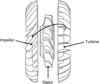
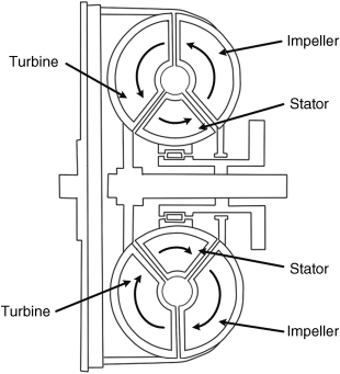
Figure 1.16 A schematic of the torque converter
Fluid slippage in a torque converter makes it impossible to achieve a perfect coupling phase. Specifically, it causes engine power loss, which negatively affects the high-speed efficiency of automatic transmission/transaxle systems. Modern torque converters are equipped with an internal locking clutch, known as a converter lock-up clutch. These locking mechanisms eliminate fluid slippage during vehicle cruising by locking the torque converter components. They also improve the fuel efficiency of automatic transmission/transaxle systems and reduce the amount of heat that the system generates. The lock-up clutch disengages at low speeds to prevent engine stalls. An electrical solenoid controls the function of the lock-up clutch. The fluid from the impeller still strikes the turbine vanes while the vehicle is idling; however, it does not carry enough kinetic energy to rotate the turbine. This causes the gear set to disconnect from the engine in an attempt to prevent the engine stalling.
1.6.2.2 Planetary Gear Sets
The function of regulating the output engine torque in an automatic transmission/transaxle system occurs through one or more set of gear sets with a special structure, called planetary gear sets. A basic planetary gear set is composed of three different-sized gears: the sun gear, the planet gears, and the ring gear. The sun gear is mounted on a shaft placed at the center of the gear unit while the planet gears (connected to the planet carrier) rotate around it. A ring gear with internal teeth encircles the sun and planet gears.
The planetary gears are always in mesh with sun and ring gears and rotate between these two gears. Each part of the planetary gear set rotates by engine power or is locked by a series of clutches and bands. The motion combinations and power manipulation of these gears provide different gear ratios. For example, a low ratio occurs if the sun gear locks while the planet gears and ring gear rotate. Likewise, when the planetary carrier is the driven component, a gear reduction occurs. In contrast, if the planetary carrier is the driving component, this results in overdrive. A planetary gear set acts as a solid unit when two of its gears lock, resulting in a direct drive.
It is impossible to achieve all the required gear ratios with a single planetary gear set. This is because gear manipulation is limited with one set, as it only provides two forward gear ratios and one reverse. Higher gear ratios can be achieved by using compound planetary gear set configurations in automatic transmission/transaxle systems. These configurations have a structure similar to a basic planetary gear set, they can have more than one of each gear type (sun, ring, etc.). For example, a Ravigneaux compound planetary gear set has two sun gears and two sets of planet gears with a common ring gear, while a Simpson compound planetary gear set has two sets of planet gears and two ring gears with a common sun gear. The Wilson planetary gear set and the Lepelletier planetary gear set are other possible configurations with more complex structures.
1.6.2.3 Clutches and Bands
Clutches and bands are used in the gear set unit as holding devices. What distinguishes the automatic transmission/transaxle system from the manual transmission/transaxle system is the controlled hydraulic in the gear set unit. Gear shifting is typically manipulated through these components, which are controlled by a mechanical hydraulic control system or electrical hydraulic systems. During gear shifting, clutches and bands work by making specific gears of a planetary gear set fixed and motionless. They do this by locking it to the transmission/transaxle case or to the shaft it is mounted upon, while allowing other gears to rotate. Hydraulic control valves activate clutches and bands which operate based on information received from sensors about the road speed, throttle position, and engine load.
1.6.2.4 Hydraulic Control Unit
The hydraulic control unit directs the gear shifts to correspond with the vehicle operating conditions by sending the pressurized hydraulic fluid to a series of clutches and bands. A pump driven by the torque converter pressurizes and circulates transmission fluid throughout the transmission/transaxle to activate various elements. The pressure built by the pump is known as the line pressure and is the activation source of the various transmission/transaxle components. The vacuum modulator, the throttle valve, and the governor valve provide the required information to the transmission control system by adjusting the line pressure. The governor provides the engine speed to the transmission control system while the throttle valve determines the throttle position. The vacuum modulator sends the engine load information to the transmission control system.
In modern automatic transmission/transaxle systems, the hydraulic pressure is electronically controlled in accordance with the information obtained from input sensors, used in place of governor and throttle valves as well as the vacuum modulator. Using electronic control systems improves the efficiency of the transmission/transaxle systems by providing more precise gear shifting in accordance with the engine demands, thereby resulting in better fuel economy and lower emissions.
1.6.3 Automated Manual Transmissions (AMTs)
As previously mentioned, a simpler structure, better fuel economy, and superior efficiency are the most desirable aspects of a manual transmission while being more comfortable to drive and easier to use are the best features of an automatic transmission system. An intermediate solution bridging these two systems is the automated manual transmissions, also known as semi-automatic transmission systems. The design of the system takes advantage of the best features of both transmissions.
In this transmission, the driver has the option of using a fully automated mode or shift manually by using switches or levers. Two main variations of the automated transmission system include sequential manual transmission and dual-clutch transmission. The automated transmission system provides better fuel efficiency, lower emissions, lower energy loss, and a more comfortable ride than either manual or automatic transmission systems.
1.6.4 Continuous Variable Transmissions (CVTs)
Unlike the limited number of gear ratios that automatic and manual transmission/transaxle systems offer, a continuous variable transmission (CVT) system provides an unlimited number of gear ratios within the upper and lower limits of their operating range. CVTs do this by properly adjusting the geometrical configuration of the system without using a set of gears. A specific type of CVT is the infinitely variable transmission (IVT) system, in which the gear ratio ranges from zero to the highest ratio. The zero ratio decouples the engine load from the driveshaft, thus making idling possible.
Generally, CVT transmission systems allow the engine to function at an optimal and efficient range of operation under varying driving conditions. This efficiency results in enhanced fuel economy, reduced emissions, and improved vehicle performance. Since there are no gears in CVTs, the gear ratio refers to the speed ratio of the input and output shafts of the transmission system. Additionally, the continuous and smooth gear change of CVTs offers more comfort, superior acceleration performance, and a lightweight transmission system with a compact structure. Conversely, the negative aspects of CVTs include its noisier performance and lower torque capacity. Due to technological advances and the afore-mentioned advantages, these transmission systems have found their way into the automotive industry. Currently, several car manufacturers have integrated CVT technology into their products.
There are various types of CVTs currently available, including the spherical, hydrostatic, magnetic, ratcheting, cone, radial roller, and toroidal CVTs. A general way to classify CVTs is by determining whether they are mechanical or non-mechanical systems. Mechanical systems are further available as friction and ratcheting systems, while non-mechanical systems can be sub-divided between hydraulic and electrical. Currently, the most commonly used CVT systems are variable-diameter pulley or pulley-based CVTs, toroidal or roller-based CVTs, and hydrostatic CVTs.
1.6.4.1 Pulley-Based CVTs
Pulley-based CVTs – classified as friction-based mechanical CVTs – are the most commonly integrated CVT designs in vehicle powertrain systems. The main components of this design are two variable-diameter pulleys and a high-density rubber or metal belt. One pulley, known as the driving pulley, receives power from the engine through the crankshaft, while the second pulley, called the driven pulley, transfers the adjusted power to the differentials through the driveshaft. A hydraulic cylinder actuates pulleys of the CVT. Each pulley is composed of a pair of cones facing each other where one of the cones is fixed while the other one can move along its center axes. One of these cones is stationary, while the other one can move along its center axes. A V-belt rubber/metal belt with a fixed length connects the pulleys to each other and transfers the power from the driving pulley to the driven one. For vehicle applications, it is more common to use metal belts, which do not have the limitations of rubber belts. Hydraulic cylinders, sensors and microprocessors are other components of a pulley-based CVT. They adjust the pulley diameter based on the engine load and driving conditions.
CVTs change the gear ratio by adjusting the diameter of the driving and driven pulleys on which the belt rides. For example, if the moveable cone is forced to move closer to the fixed cone, the belt operating between them rides higher to increase the diameter of the pulley. In contrast, when the moveable cone is forced to move far away from the fixed one, the belt rides lower in the groove, resulting in a decrease in pulley diameter. Electronically controlled movements of the cones in each pulley make the diameter adjustments. The fixed belt length means that increasing the diameter of one pulley requires a reduction in the diameter of the other pulley. The diameter changes between the pulleys allow the vehicle to operate on an unlimited number of gear ratios. For instance, the smaller diameter of the driving pulley causes a lower speed of the driven pulley, thus producing a lower gear ratio. Similarly, the larger diameter of the driving pulley with respect to the driven one results in a higher gear ratio.
The main disadvantages of pulley-based CVTs include excessive build-up of heat and sensitivity to wear because of the friction generated at the contact points. Lubricating oil can help resolve these issues at the cost of reducing the friction and torque capacity of the system. In addition, slippage in the drive belt may occur in the high torque demand condition such as when a vehicle accelerates from a stop at peak torque, thereby resulting in power loss.
1.6.4.2 Toroidal CVTs
Like pulley-based CVTs, toroidal CVTs are also friction-based. The primary advantage of toroidal CVTs is their parallel power flow, which allows the system to have a high torque capacity and compact design. The main operation of a toroidal CVT is similar to that of a pulley-based CVT. However, unlike the belts and pulleys used by pulley-based CVTs, toroidal CVTs use discs and power rollers or wheels (Figure 1.17). In toroidal CVTs, one disc connects to the engine crankshaft while the other one connects to the driveshaft. Power transfers from the driving disc to the driven disc through the rollers or wheels located between them, which spin around the horizontal axis. The rollers located between the discs adjust the gear ratio based on how they are angled relative to the discs. As such, even a slight tilt in the roller/wheel angle around the vertical axis can incrementally adjust the gear ratio. For example, lower gear ratios can be achieved when the rollers/wheels are in contact with the driving disk near the center while they are in contact with the driven disk near the rim.
Two variations of toroidal CVTs are the full toroidal and the half-toroidal CVT. The difference between these two subtypes is the position of the tilting rotation center. In a half-toroidal CVT (Figure 1.18a), the power roller tilting rotation center is outside the center of the cavity between the discs. As shown in Figure 1.18b, in a full toroidal CVT, however, the titling rotation center of the power roller coincides with the center of cavity between discs. Ultimately, half-toroidal CVT designs are more efficient than full-toroidal drives at the expense of a lower torque capacity. The disadvantages of toroidal CVTs are similar to those of pulley-based CVTs.
Figure 1.17 Operation of the half-toroidal CVT
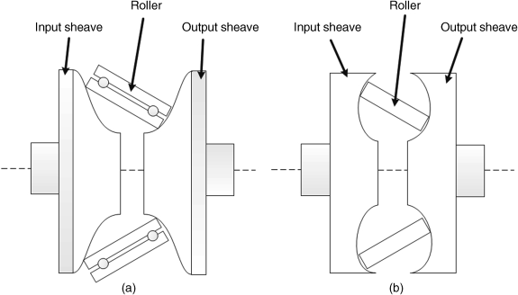
Figure 1.18 Half-toroidal (a) and full-toroidal (b) CVT types
1.6.4.3 Hydrostatic CVTs
A hydrostatic CVT is a mechanical CVT with at least one variable-displacement pump and one motor. The hydrostatic pump connects to the engine and converts the output mechanical power of the engine into fluid power. Through the hydraulic motor, this power is converted into rotational power at the output shaft.
Proper control of the hydraulic flow can change the gear ratio. Usually, hydraulic CVTs combine the use of a planetary gear set and clutches to improve the overall efficiency of the transmission system. Typically, the hydraulic system transmits power at low speeds while the planetary gear set transfers power in high-speed conditions. Hydrostatic CVTs are capable of transmitting more torque at the expense of sensitivity to contamination and higher costs. Heavy-duty agricultural and off-road vehicles often have this type of transmission system.
1.7 Drivetrain and Differentials
The drivetrain is the last unit in a powertrain system that transfers the engine power to the road. The main components of the drivetrain unit include the driveshaft, the differentials, axle shafts, and wheels. Of these, the differential is the most important component. The driveshaft is the input to the differential, while the axle shafts are its output. A differential is a gearbox that directs and adequately distributes the engine power to the driving wheels. Additionally, it allows the driving wheels on either side of the vehicle to independently rotate at different speeds. This is important in improving the handling performance of the vehicle during cornering. When cornering, the outside wheels need to spin faster than the inside ones because the inside wheels travel across a shorter distance. Otherwise, the wheels would lock into the same rotational speed, resulting either in the inside or outside wheel skipping and losing traction. This lack of traction would cause unexpected handling difficulties, tire damage, and strains on the drivetrain.
Note that the sum of the split power between the left and right wheels is equal to the total power received from the engine. Similarly, the average sum of the rotational speed of the wheels is equal to the driveshaft's rotational speed. In other words, if the rotational speed of one wheel is rising, the speed of the opposite wheel must compensate by an equal reduction.
Usually, a vehicle has one differential unit that is located in the middle of either the front or the rear-driving axle, depending on the vehicle type. All-wheel drive and four-wheel drive vehicles typically have three differentials, with two of them located on the front and rear axles in order to direct engine power to the right and left wheels. In this arrangement, the third differential splits the engine power between the front and rear axles. There are various designs of differentials integrated into vehicles based on vehicle performance and functionality. The most important differentials include open differentials, limited slip differentials, locking differentials, and transfer case differentials.
1.7.1 Open Differentials
Figure 1.19 is a schematic of an open differential system. Open differentials, also known as standard differentials, are the most common differentials in modern vehicles. They include two side gears, a set of spider gears (known as planetary gears), the ring gear, and the differential case. The driveshaft rotates the ring gear bolted to the differential case. The spider gears then rotate with the differential case and can also rotate along their own shaft axes. Each side gear is connected to an axle shaft and is driven by the spider gears. These spider gears allow the outside and inside wheels to move at different velocities during cornering.
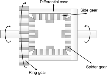
Figure 1.19 Schematic of an open differential system
On paved roads, the open differential system works well and provides adequate handling performance. However, if the wheels encounter unequal traction conditions, power routes to the wheel with the least amount of traction. This causes unexpected handling performance for the driver and can hinder the vehicle's motion. For example, if one wheel spins on a slippery surface while another is on a dry surface, all the power is directed towards the wheel on the slippery road, leaving the other wheel to receive minimal or no power. The design of limited slip differentials and locking differentials addresses the limitations of open differentials on uneven traction conditions.
1.7.2 Limited Slip Differentials
The design of limited slip differentials resolves the limitations of open differentials in conditions where traction is lost. However, resolving this issue also comes at the expense of a more complex system. “Limited slip” refers to the function of the system in limiting wheel spin. In this design, the differential operation is limited when the traction loss of any wheel exceeds a certain threshold. It then redirects power to the wheel with more traction by up to 80%, thereby maintaining rotational power in both wheels. Limited slip differentials are used mainly in off-road vehicles since it is possible for one of the wheels to lose traction in off-road conditions. In addition, high-speed performance vehicles utilize these differentials to improve vehicle handling during high-speed cornering, when the different velocities of the left and right wheels may lead to higher amounts of differential slip.
Limited slip differentials have various designs; the most important ones include mechanical, viscous coupling, and electronic limited slip differentials. Mechanical limited slip differentials are based on the interaction between two (or more) mechanical parts. Clutch, cone, and helical gear limited slip differentials belong in this category. In the viscous coupling variation, the differential slip is controlled by the hydrodynamic friction from fluids with high viscosity. These differentials are less efficient than the mechanical ones because power loss occurs during activation. However, in modern vehicles, electronic limited slip differentials are used to activate the mechanical components of the system. An electronic limited slip differential utilizes different sensors and microcomputers in order to monitor the wheel slip and vehicle motion.
1.7.3 Locking Differentials
The design of locking differentials, also known as lockers, enables the wheels on an axle to lock relative to each other, avoiding the difference in speed between two wheels on the axle, regardless of the amount of traction on each wheel. Automatic and selectable lockers are two variations of locking differential systems. The automatic differentials lock both wheels on the axle under normal conditions, while they unlock the differential for certain conditions such as cornering. Automatic lockers automatically lock and unlock the differential system, thereby causing fast-changing and strange handling characteristics on the street. The function of the differential is noisy and increases tire wear. Off-road four-wheel drive vehicles are the main applications of the automatic lockers and typically, they are integrated on the rear axles only, since front axle installations can cause difficulties in steering. In contrast, a selectable locker functions as an open differential in normal driving conditions; however, the driver has the option of locking both wheels on the axle. When locked, both axles will then turn at the same speed irrespective of the road surface. The locking process can occur through compressed air, mechanical cable, electric actuator or hydraulic fluid. It is possible to integrate selectable lockers in both front and rear axles without sacrificing vehicle handling performance and tire wear. Off-road vehicles are the main applications of such differentials. The integration of the selectable differentials on on-road vehicles is limited due to the high cost and complexity of installation.
1.7.4 Transfer Case Differentials
Typically, four-wheel and all-wheel drive vehicles have three differentials, two of which are mounted on the front and rear axles, whereas the third one, called the transfer case, is located between the front and rear output shafts to the final drive units. Attached to the rear of the transmission and also to the front and rear axles through two separate driveshafts, the transfer case and center differentials are mechanical devices which split the power between the front and rear axles while varying the distribution of power between the front and rear axles smoothly and over a certain range. In addition, they adjust the speed differences in front and rear axles. The transfer case receives the power directly from the transmission and directs it to either the rear wheels or both the front and rear wheels. The transfer action may occur through a set of gears or through a chain-driven device. Through the transfer case, the driver has the option of selecting two-wheel drive or four-wheel drive mode by a shifter. However, some vehicles accomplish this electronically through a switch. Some transfer cases are not selectable such as all-drive vehicles.
Problems
1. What is the principle of energy efficiency in internal combustion engines and how does it differ between diesel and gasoline engines (explain in detail)?
2. What is the difference between engine knocking and pre-ignition phenomena?
3. What is the stoichiometric ratio of CNG, LPG, hydrogen, ethanol, and methanol? How can it affect the engine performance?
4. What is the difference between a supercharger system and a turbocharger system?
5. Why do some modern diesel engines use a throttle valve in their fuel system? Explain how this valve reduces vehicle emissions.
6. What is a carburetor? Provide reasons explaining why it has been replaced by controlled fuel injection systems.
7. Investigate the effects of ignition timing on the emissions of a gasoline engine.
8. What is the contribution of vehicular air pollution on your city and country? Conduct research on your government's policies on air pollution reduction.
9. How does the waste-gate in a turbocharger regulate the intake air pressure? Explain.
10. Describe the operating characteristics of a three-way catalyst.
11. Describe the operating characteristics of diesel catalytic converters.
12. Conduct research on new advances in gasoline and diesel engine emission control technologies.
13. Research and find other alternative fuels available on the market. Discuss the advantages and disadvantages of these options.
14. What is the market share of vehicles with alternative fuel systems? What are the main obstacles preventing these vehicles from mass production in your local area?
15. What is the difference between a transfer case and a center differential?
16. How does a manual transmission system work? Explain.
17. Describe the structure and function of a clutch in a manual transmission/transaxle system.
References
- 1. http://www1.eere.energy.gov/vehiclesandfuels/avta/light_duty/fsev/fsev_history.html.
- 2. http://www.hybridcars.com/history/history-of-hybrid-vehicles.html.
- 3. http://www.sustainable-mobility.org/month-issue/decoding/histoiry-of-the-electric-vehicle-along-development-process.html.
- 4. http://inventors.about.com/library/weekly/aacarsgasa.htm.
- 5. http://www.speedace.info/internal_combustion_engine.htm.
- 6. Jong, R.Ahman, M., Jacobs, R., and Dumitrescu, E. (2009) Hybrid Electric Vehicles: An Overview of Current Technology and Its Application in Developing and Transitional Countries, UNEP, Washington, DC.
- 7. Taylor, C.F. (1985) The Internal-Combustion Engine in Theory and Practice: Combustion, Fuels, Materials, Design, 2nd edn, MIT Press, Cambridge, MA.
- 8. Wallington, T.J., Kaiser, E.W., and Farrell, J.T. (2006) Automotive fuels and internal combustion engines: a chemical perspective. Chemical Society Reviews, 35, 335–347.
- 9. http://www.epa.gov/.
- 10. http://www.energy.gov/.
- 11. http://www.eia.gov/.
- 12. http://www.iea.org/.
- 13. Lipman, T.E., and Delucchi, M.A. (2002) Emissions of nitrous oxide and methane from conventional and alternative motor vehicles. Climate Change, 53, 477–516.
- 14. https://www.princeton.edu/ssp/64-tiger-cub-1/64-data/combustion-chemistry.pdf.
- 15. Wallington, T.J., Sullivan, J.L., and Hurley, M.D. (2008) Emissions of CO2, CO, NOx, HC, PM, HFC-134a, N2O and CH4 from the global light duty vehicle fleet. Meteorologische Zeitschrift, 12(2), 109–116.
- 16. http://www.meca.org/galleries/default-file/MECA%20Diesel%20White%20Paper%2012-07-07%20final.pdf.
- 17. http://ec.europa.eu/enterprise/sectors/automotive/files/pagesbackground/emission_control/vol_1-emission_control_technology_en.pdf.
- 18. http://www.aecc.be/en/Technology/Catalysts.html.
- 19. http://www.volvoscr.com/default.aspx?pageid=3362.
- 20. http://www.autoshop101.com/forms/h61.pdf.
- 21. http://www.ika.rwth-aachen.de/r2h/index.php/Hydrogen_Internal_Combustion_Engine.
- 22. Reimpell, J., Stoll, H., and Betzler, J.W. (2001) The Automotive Chassis: Engineering Principles, 2nd edn, Butterworth-Heinemann, Oxford.
- 23. Wagner, G. (2001) Application of transmission systems for different driveline configurations in passenger cars, SAE Technical Paper 2001-01-0882, 2001, DOI: 10.4271/2001-01-0882.
- 24. Kluger, M., and Long, D. (1999) An overview of current automatic, manual and continuously variable transmission efficiencies and their projected future improvements, SAE Technical Paper 1999-01-1259, 1999, DOI: 10.4271/1999-01-1259.
- 25. Johanson, C., and Duffy, J.E. (2010) Automatic Transmissions and Transaxles, A2, 3rd edn, the Goodheart-Willcox Co., Inc, ISBN: 978-1-60525-203-2.
- 26. Iannelli, L. (2011) Automated transmission systems: the impact of control technology, in IEEE Control Systems Society (eds T. Samad and A.M. Annaswamy), available at: www.ieeecss.org.
- 27. Renius, K.T., and Resch, R. (2005) Continuously variable tractor transmissions. Paper presented at ASAE – the Society for Engineering in Agricultural, Food, and Biological Systems, the 2005 Agricultural Equipment Technology Conference, Louisville, Kentucky.
- 28. Imanishi, T., and Machida, H. (2001) Development of POWERTOROS unit half-toroidal CVT(2): comparison between half-toroidal and full-toroidal CVTs. NSK Technical Journal Motion and Control, 10, April.