Multiple Choice Questions
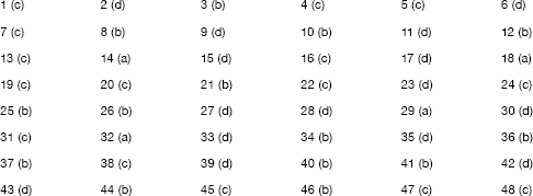
1. If the secondary winding of the ideal transformer shown in Figure 1 has 40 turns, the number of turns in the primary winding for maximum power transfer to the 2 Q resistor will be
- (a) 20 (b) 40 (c) 80 (d) 160
Figure 1
2. If the rated voltage from the power lines is applied to the primary of a single-phase transformer which is operated on no-load, then
- (a) both input voltage and current are sinusoidal
- (b) both input voltage and current are non-sinusoidal
- (c) input voltage is non-sinusoidal and current are sinusoidal
- (d) input voltage is sinusoidal and current are non-sinusoidal
3. For the purpose of analysis, an exact equivalent circuit of a transformer is usually replaced by an approximate equivalent circuit. In doing so errors loss is of differential nature. Due to this, the analysis by approximate equivalent circuit gives fairly satisfactory results. Under the circumstances, which one of the following is an equivalent circuit as compared to the exact equivalent circuit?
- (a) This accounts for somewhat greater primary winding copper loss and lesser core loss.
- (b) This accounts for somewhat lesser primary winding copper loss and greater core loss.
- (c) This accounts for somewhat greater secondary winding copper loss and lesser core loss.
- (d) This accounts for somewhat lesser secondary winding copper loss and greater core loss.
4. At 50 Hz operation, a single-phase transformer has hysteresis loss of 200 W and eddy current loss of 100 W. Its core loss at 60 Hz operation will be
- (a) 432 W (b) 406 W (c) 384 W (d) 360 W
5. A 2 kVA transformer has iron loss of 150 W and full-load cupper loss of 250 W. The maximum efficiency of the transformer would occur when the total loss is
- (a) 500 W (b) 400 W (c) 300 W (d) 275 W
6. If the frequency of input voltage is increased keeping the magnitudes of voltage unchanged, then
- (a) both hysteresis and eddy current losses in the core will increase
- (b) hysteresis loss will increase and eddy current loss will decrease
- (c) hysteresis loss will decrease and eddy current loss will increase
- (d) hysteresis loss will decrease and eddy current loss will remain unchanged
7. The voltage regulation of transformer at full load and 0.8 power factor lagging is 2.5 per cent. The voltage regulation at full-load and 0.8 power factor leading will be
- (a) -2.5% (b) zero (c) 1% (d) 2.5%
8. For successful operation of two single-phase transformers, the most essential condition is that their
| (a) percentage impedances are equal | (b) polarities are properly connected |
| (c) turns ratios are exactly equal | (d) kVA ratings are equal |
9. In a transformer, if the iron losses and copper losses are 40.5 kW and 50 kW, respectively, then at what fraction of load will the efficiency be maximum?
- (a) 0.60 (b) 0.57 (c) 0.70 (d) 0.90
10. Can a 50 Hz transformer be used for 25 Hz, if the input voltage is maintained constant at the rated value corresponding to 50 Hz?
- (a) Yes. As the voltage is constant, current levels will not change.
- (b) No. Flux will be doubled, which will drive the core to excessive saturation.
- (c) No. Owing to decreased reactance of transformer, input current will be doubled at load.
- (d) Yes. At constant voltage, insulation will not be overstressed.
11. The short circuit test is performed on a transformer with a certain impressed voltage at rated frequency. If the short circuit test is now performed with the same magnitude of impressed voltage, but at a frequency higher than the rated frequency, then
- (a) both the magnitude of the current and the power factor will increase
- (b) the magnitude of the current will decrease but the power factor will increase
- (c) the magnitude of the current will increase but the power factor will decrease
- (d) both the magnitude of the current and the power factor will decrease
12. Which of the following regarding a transformer is correct?
- (a) In transformers, a laminated core is used to reduce copper losses.
- (b) Core losses in a transformer can be determined by an open circuit test.
- (c) Short circuit test is conducted on a transformer to determine constant losses.
- (d) In a shell-type transformer, the primary and secondary windings are wound on separate limbs.
13. The main purpose of the conservator in a transformer is to
- (a) store extra oil to compensate for the loss of oil due to leakage
- (b) achieve better cooling of the transformer
- (c) take up the expansion of oil due to heating
- (d) have the Buchhloz relay fitted
14. Which of the following statements are incorrect?
- i. The maximum voltage regulation of transformer occurs at leading power factor.
- ii. The voltage regulation of a transformer is maximum when the load power factor (lagging) angle has the same value as the angle of equivalent impedance.
- iii. The voltage regulation of a transformer at zero power factor is always zero.
- iv. The voltage regulation of a transformer can be negative at leading power factor.
Select the correct answer using the codes given below:
- (a) i and iii (b) ii and iii (c) ii and iv (d) i and iv
15. When a short circuit test is conducted on a single-phase transformer, 30 per cent of the rated voltage is required to allow full-load current. The short circuit power factor is found to be 0.2. The percentage regulation at unity power factor (UPF) is
- (a) 30 (b) 29.5 (c) 15 (d) 6
16. Capacitance voltage transformer (CVT) is used to
- (a) improve the power factor of the transmission
- (b) reduce losses in a transmission line
- (c) connect instruments on the low tension side
- (d) reduce the incidence of overvoltage surges on transmission lines
17. A transformer designed for operation on 60 Hz supply is worked on 50 Hz supply system withoutchanging its voltages and current ratings. When compared with full load, efficiency at 60 Hz, the transformer efficiency on full load at 50 Hz will
| (a) increase marginally | (b) increase by a factor of 1.2 |
| (c) remain unaltered | (d) decrease marginally |
18. A transformer has a core loss of 200 W and full-load copper loss of 800 W. The maximum efficiency of the transformer will occur at
| (a) 0.5 times full-load current | (b) 0.6 times full-load current |
| (c) 0.7 times full-load current | (d) 0.8 times full-load current |
19. If the primary winding of a 100 kVA transformer is connected to the direct supply,
- (a) the voltage induced in the secondary will be direct voltage
- (b) back emf will be induced in the primary winding
- (c) the primary winding may burn
- (d) low voltage will be induced in the secondary
20. A 480/120 V, 5 kVA, two-winding transformer is to be used as an autotransformer to supply power at 480 V from 1,600 V supply. The kVA rating of the autotransformer will be
- (a) 5 (b) 15 (c) 25 (d) 50
21. A 100 kVA transformer has copper loss of 100 W at full load and iron loss of 100 W. Under which of the following conditions, the efficiency of the transformer will be
- (a) half load, unity power factor
- (b) half load, 0.8 power factor (lagging)
- (c) 4th of full load, unity power factor
- (d) 4th of full load, 0.8 power factor (lagging)
22. For the transformer cores, cold-rolled silicon steel is preferred to hot-rolled silicon steel because of
| (a) lower cost | (b) higher tensile strength |
| (c) higher flux density | (d) affinity for oil |
23. In transformers, interleaved disc connection is used for
- (a) welding transformers
- (b) step-down transformers
- (c) low-voltage low-current transformers
- (d) high-voltage transformers
24. The function of breather in a transformer is to
- (a) provide oxygen to the oil
- (b) provide cooling air
- (c) arrest moisture entering the transformer
- (d) filter the transformer oil
25. The transformer has the turns ratio of 2:1 (primary to secondary). If peak-to-peak value of secondary voltage is 220 V, the primary voltage will be
| (a) 220 V rms | (b) 440 V peak-to-peak |
| (c) 300 V rms | (d) 220 V rms |
26. Which relay is used to protect the transformer from inter turn fault?
- (a) Air blast relay (b) Buchholz relay (c) Mho relay (d) None of these
27. High-frequency transformers use
- (a) aluminium core (b) iron core (c) copper core (d) air core
28. The efficiency of a well-designed transformer may be expected in the range
- (a) 75-80% (b) 65-70% (c) 85-90% (d) 95-99%
29. Two similar, 250 kVA, single-phase transformers gave the following results when tested by back-to-back method:
Mains wattmeter, W1 = 5.0 kW
Primary series circuit wattmeter, W2 = 7.5 kW (at full-load current)
The individual transformer efficiency at 75 per cent full load and 0.8 pf load will be nearly
- (a) 97% (b) 95% (c) 93% (d) 90%
30. What is a typical use of an autotransformer?
| (a) toy transformer | (b) control transformer |
| (c) variable transformer | (d) isolating transformer |
31. The insulating properties of transformer oil are adversely affected by the presence of
- (a) oxygen (b) copper (c) moisture (d) ozone
32. In a transformer on no-load, the input voltage
- (a) leads magnetising current by 90°
- (b) lags magnetising current by 90°
- (c) is in phase with the magnetising current
- (d) is always at 45° to the magnetising current
33. An autotransformer is preferred in cases where
| (a) load is fluctuating | (b) power factor is varying |
| (c) ratio of transformation is low | (d) ratio of transformation is high |
34. In transformers, disc coils are generally preferred for
| (a) leading power factor | (b) high-voltage winding |
| (c) constant load | (d) low-voltage winding |
35. Buchholz relay works on the principle of
- (a) production of eddy currents whenever load changes are rapid
- (b) ionization of transformer oil
- (c) magnetic hum due to sudden variation of load
- (d) generation of gas due to breakdown of the insulation
36. The results of open-circuit test to a single-phase transformers are
Voltage applied: 100 V
Current drawn: 0.5 A Power consumed: 30 W
The corresponding reactance of the transformer is
- (a) 200 Q (b) 250 Q (c) 400 Q (d) 500 Q
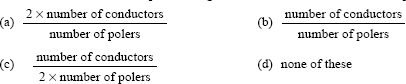
37. For a 100 per cent efficient transformer if the number of turns in the primary and secondary are 1,000 and 100, respectively and the input to the transformer is 100 W, the power output is
- (a) 100 W (b) 1,000 W (c) 10 kW (d) 100 kW
38. Under operating conditions, the secondary of a current transformer is always short circuited because
- (a) it protects the primary circuit
- (b) it is safe to human beings
- (c) it avoids core saturation and high-voltage induction
- (d) none of the above
39. Which of the following transformer is smallest?
- (a) 1 kVA, 50 Hz
- (b) 1 kVA, 200 Hz
- (c) 1 kVA, 400 Hz
- (d) 1 kVA, 600 Hz
40. What special precaution should be taken when using a booster transformer?
- (a) It should never be left open-circuit.
- (b) There should be no fusing in the high-voltage side.
- (c) It should never be left close circuit.
- (d) None of the above.
41. Helical coils are very well suited for
- (a) high-voltage winding of small-rating transformer
- (b) low-voltage winding of large-rating transformer
- (c) high-voltage winding of large-rating transformer
- (d) none of the above
42. In parallel operation of two single-phase transformers, if the impedance triangles of the transformers are not identical in shape and size
- (a) power factors at which the transformers operate will be same but different from the power factor of common load
- (b) power factors at which the transformers operate and the power factor of common load will be the same
- (c) power factor of one transformer and the power factor of common load will be the same
- (d) power factors at which the transformers operate will be different from one another and again these will be different from the power factor of common load
43. On which factor does the short circuit voltage of a transformer mainly depend?
- (a) on the ohmic resistance of the primary winding
- (b) on the ohmic resistance of the secondary winding
- (c) cross-sectional area of the iron core
- (d) magnitude of the leakage flux
44. A 100 kVA transformer has copper loss of 1,000 W at full load and iron loss of 1,000 W. At half the full load and 0.8 power factor (lagging), the efficiency of the transformer will be
- (a) 98.91% (b) 96.97% (c) 95% (d) 91.91%
45. Eddy current losses in a transformer are minimised by laminating the core, interlamination insulation being provided by
| (a) thick paper insulation | (b) thin sheets of mica |
| (c) a thin coat of core plate varnish | (d) none of the above |
46. Use of higher flux density in the transformer design
| (a) increases the weight/kVA | (b) decreases the weight/kVA |
| (c) reduces iron loss | (d) improves insulation |
47. In a transformer, the primary and secondary voltages are
| (a) 60° out of phase | (b) 90° out of phase |
| (c) 180° out of phase | (d) always in phase |
48. The efficiency of a transformer at full load 0.8 pf lagging is 95 per cent. Its efficiency at full load 0.8 pf leading will be
- (a) 80% (b) 90% (c) 95% (d) 100%
49. Steel used in the construction of transformer core has
| (a) low permeability and low hysteresis loss | (b) low permeability and high hysteresis loss |
| (c) high permeability and high hysteresis loss | (d) high permeability and low hysteresis loss |
50. Transformer oil should be designed free from
- (a) moisture (b) sulphur (c) alkalis (d) all of these
51. The leakage flux of a transformer depends on
- (a) supply frequency (b) load current (c) mutual flux (d) none of these
52. The no-load current of a transformer in terms of full-load current is typically
- (a) 1- 4% (b) 4 - 12% (c) 12 - 16% (d) 16 - 20%
53. Good transformer oil should not have water more than
- (a) 4 ppm (b) 8 ppm (c) 12 ppm (d) 20 ppm
54. A transformer is connected to a constant voltage supply. As the supply frequency increases, the magnitude of the flux in the core
| (a) decreases | (b) increases towards saturation |
| (c) becomes zero | (d) becomes constant |
55. The size of the transformer core depends on
| (a) frequency | (b) flux density of the core |
| (c) both (a) and (b) | (d) cross-sectional area of the core |
56. If we impress a DC voltage of 230 V to an unloaded 230 V, 50 Hz transformer, the transformer will
- (a) burn out
- (b) give very high secondary voltage
- (c) give secondary voltage according to turns ratio
- (d) none of the above
57. Ferrite cores have less eddy current losses than iron losses because ferrites have
| (a) low permeability | (b) high hysteresis |
| (c) high resistance | (d) all of these |
58. If a two-winding step-down transformer is converted into an autotransformer by using additive polarity, then
- (a) kVA rating gets reduced
- (b) kVA rating increases considerably
- (c) kVA rating remains unaltered
- (d) a large number of secondary taps are needed
59. Incorrect polarity in parallel operation results in
- (a) open circuit
- (b) short circuit
- (c) load sharing proportional to their kVA rating
- (d) regeneration of power
60. In parallel operation of transformers, to reduce copper loss
| (a) they should have equal turns ratio | (b) their phases should be same |
| (c) they should have zero impedance | (d) none of the above |
61. Power transformers are designed to have maximum efficiency at
| (a) a little more than full load | (b) near full load |
| (c) half load | (d) quarter load |
62. Scott connection is used to transform
- (a) single-phase supply into two-phase supply
- (b) two-phase supply into single-phase supply
- (c) three-phase supply into two-phase supply
- (d) two-phase supply into three-phase supply
63. The iron losses of a transformer may be calculated by knowing the weight of
| (a) yokes alone | (b) cores alone |
| (c) cores and yoke | (d) copper winding alone |
64. Other things remaining same, the efficiency of an auto-transformer compared to a two-winding transformer is
- (a) lower (b) the same (c) higher (d) dependent of load
65.pecial silicon steel is used for laminations in power transformer to reduce
| (a) eddy current loss | b) hysteresis loss |
| (c) copper losses | (d) both (a) and (b) |
66. The reactance of a transformer is defined by its (a) leakage flux
| (a) leakage flux | (b) common core flux |
| (c) permeability of the core material | (d) size of the cores |
67. Concentric windings are used in core type transformer with
| (a) LT winding placed next to core | (b) HT winding placed next to core |
| (c) LT winding on the outer side | (d) HT winding on the outer side |
68. Oil natural cooling with tubes is used for transformers of capacity
- (a) 100 kVA (b) 500 kVA (c) 1,000 kVA (d) 3,000 kVA
69. The magnetic flux in a transformer follows a path of
| (a) high reluctance | (b) low reluctance |
| (c) high conductivity | (d) low conductivity |
70. The magnetic coupling between the primary and secondary of a transformer may be increased by
| (a) increasing the number of laminations | (b) changing the turns ratio |
| (c) using the magnetic core of low reluctance | (d) none of the above |
71. For minimum weight of a transformer, the weight of iron should be
| (a) less than the weight of copper | (b) greater than the weight of copper |
| (c) equal to the weight of copper | (d) none of these |
72. A constant current transformer should not have
- (a) a high value of reactance
- (b) a movable secondary winding
- (c) a high value of resistance
- (d) primary and secondary windings surrounding the core
73. Transformers transform
- (a) frequency (b) voltage (c) current (d) power
74. An ideal power transformer will have maximum efficiency at a load such that
| (a) copper loss is less than iron loss | (b) copper loss is equal to iron loss |
| (c) copper loss is higher than iron loss | (d) none of the above |
75. Two transformers operating in parallel will share the load depending on their
| (a) rating | (b) leakage reactance |
| (c) efficiency | (d) per unit impedance |
76. If the applied voltage of a certain transformer is increased by 50 per cent and the frequency is reduced to 50 per cent (assuming that the magnetic circuit remains unsaturated), the maximum core flux density will
- (a) change to three times the original value
- (b) change to 1.5 times the original value
- (c) change to 0.5 times the original value
- (d) remain the same as original value
77. The low-voltage winding of a core-type transformer is subdivided into two equal halves, each half having the original width of the single winding with the high-voltage winding (instead of having the usual construction of low-voltage winding adjacent to the core and surrounded by the high-voltage winding). Such an interlacing of coils would make the combined primary and secondary leakage reactance (in terms of the primary) nearly
- (a) twice (b) equal (c) half (d) one-fourth
78. In a transformer fed from a fundamental frequency of voltage source, the source of harmonics is the
| (a) overload | (b) poor insulation |
| (c) iron loss | (d) saturation of core |
79. A 40 kVA transformer has a core loss of 400 W and full-load copper loss of 800 W. The proportion of full load at maximum efficiency is
- (a) 50% (b) 62.3% (c) 70.7% (d) 100%
80. A single-phase induction regulator is a constant input transformer to obtain smooth variation of the output voltage by varying the
- (a) ratio of turns between the primary and secondary windings
- (b) frequency
- (c) flux density in the core
- (d) angle between the magnetic axes of the primary and secondary windings
81. An autotransformer having a transformation ratio of 0.8 supplies a load of 10 kW. The power transferred inductively from primary to the secondary is
- (a) 10 kW (b) 8 kW (c) 2 kW (d) zero
82. Consider the following statements:
i. skewing the slots ii. fractional slot winding
iii. short-chorded winding iv. distributed winding
Of these statements
| (a) i and ii are correct | (b) ii, iii and iv are correct |
| (c) i, iii and iv are correct | (d) i and iii are correct |
83. When a transformer winding suffers a short circuit, the adjoining turns of the same winding experience
- (a) an attractive force (b) a repulsive force (c) no force
84. The core flux of a practical transformer with a resistive load
| (a) is strictly constant with load changes | (b) increases linearly with load |
| (c) increases as the square root of the load | (d) decreases with increased load |
85. A 1 kVA, 230 V/100 V, single-phase 50 Hz transformer having negligible winding resistance and leakage reactance is operating under saturation while 250 V, 50 Hz sinusoidal supply is connected to the high-voltage winding. A resistive load is connected to the low-voltage winding, which draws rated current. Which one of the following quantities will not be sinusoidal?
- (a) voltage induced across the low-voltage winding
- (b) core flux
- (c) load current
- (d) current drawn from the source
86. Two three-phase transformers are to be connected for parallel operation. Which one of the following arrangements is impossible?
- (a) Transformer A: primary Y; secondary Y
Transformer B: primary Δ secondary Δ - (b) Transformer A: primary A; secondary Y
Transformer B: primary Δ; secondary Δ - (c) Transformer A: primary Y; secondary Δ
Transformer B: primary Δ; secondary Δ - (d) Transformer A: primary Δ; secondary Δ
Transformer B: primary Δ; secondary Δ
87. If the waveform of the voltage impressed on the primary of a Y-A bank contains a 5th harmonic, the wave-forms of the resultant voltages of the primary and secondary would be
| PrimarySecondary | Secondary |
| (a)peaked | peaked |
| (b)peaked | flat-topped |
| (c)flat-topped | peaked |
| (d)flat-topped | flat-topped |
88. A 120 kVA 6,000/400 V star/star three-phase, 50 Hz transformer has an iron loss of 1,800 W. The maximum efficiency occurs at 3/4 full load. The efficiency of the transformer at full load is 0.8 pf will be
- (a) 98% (b) 95% (c) 92% (d) 90%
89. i. star-star ii. delta-delta
iii. star-delta iv. delta-star
The core section of a large transformer can work in parallel with another transformer. Identify from the above.
- (a) i and ii (b) iii and iv (c) i and iv (d) ii and iii
90. Three-phase transformers may be
| i. star-star connection | ii. delta-delta connection |
| iii. star-delta connection | iv. delta-star connection |
A star-star connected transformer can work in parallel with another transformer. Identify from the above.
- (a) i and ii (b) iii and iv (c) i and iv (d) ii and iii
91. The most suitable and economical connection for a small high-voltage transformer is
| (a) star-delta connection | (b) delta-delta connection |
| (c) delta-star connection | (d) star-star connection |
92. In a three-phase A/Y transformer shown in Figure 2, the phase displacement of secondary line voltages with corresponding primary line voltages will be
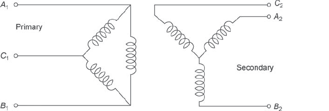
Figure 2
- (a) zero (b) 30° lag (c) 30° lead (d) 180°
93. Three three-phase transformers each rated at 75 MVA, 132 kV/11 kV have the following different methods of cooling:
- self oil cooled
- forced oil cooled
- forced air cooled
The correct sequence in ascending order in terms of the weights of these transformers is
- (a) i, ii, iii (b) ii, iii, i (c) iii, i, ii (d) iii, ii, i
94. A three-phase delta/star transformer is supplied at 6,000 V on the delta-connected side. The terminal voltage on the secondary side when supplying full load at 0.8 lagging power factor is 415 V. The equivalent resistance and reactance drops for the transformer are 1 per cent and 5 per cent, respectively. The turns ratio of the transformer is
- (a) 14 (b) 24 (c) 42 (d) 20
95. In a 110 V compound generator, the armature, shunt and series windings are 0.06 Q, 27.5 Q and 0.04 Q, respectively. The load consists of 200 lamps each rated at 55 W, 110 V Find the total emf when the machine is connected for long shunt operation
- (a) 12 V (b) 72 V (c) 100 V (d) 120 V
96. The DC generator used for arc welding purposes is a
- (a) series generator
- (b) shunt generator
- (c) cumulatively compound generator
- (d) differentially compound generator
97. A 220 V DC machine has an armature resistance of 1 Q. If the full-load current is 20 A, the difference in the induced voltages when the machine is running as a motor and as a generator is
- (a) 20 V (b) zero (c) 40 V (d) 50 V
98. A separately excited DC generator is feeding a shunt motor. If the load torque on the motor is halved approximately
- (a) armature currents of both motor and generator are halved
- (b) armature current of motor is halved and that of generator is unaltered
- (c) armature current of generator is halved and that of motor is unaltered
- (d) armature currents of both motor and generator are unaltered
99. An electric train employing a DC series motor is running at a fixed speed, when a sudden slight drop in the mains voltage occurs. This would result in
| (a) drop in speed and rise in current | (b) rise in speed and drop in current |
| (c) rise in speed and rise in current | (d) drop in speed and rise in current |
100. A DC machine has conductors per pair of poles Z, length of each armature conductor L, linear velocity of armature conductor up and air gap flux density distribution B = Bmax sin 9. The instantaneous emfs in successive conductors under one pole should be a series whose first two terms are e, = B L sin 9and e2 = B L sin (9 + 2n/Z). The last term in this series will be 1 m u 2 m u v 7
- (a) BmLu sin (9 + nIZ)
- (b) BmmLu sin (9 + n/2Z)
- (c) BmmLu sin (9 + n- nIZ)
- (d) BmmLu sin (9 + n - InIZ)
101. Consider the following statements regarding speed control of DC motors:
- Ward-Leonard method is suitable for constant torque drive.
- Field control method facilities speed control below ‘base speed'.
- 'Armature resistance control’ method is more efficient when compared to Ward-Leonard method.
- iv. Field control method is suitable for constant horse power drive.
Of these statements:
- (a) i, ii and iii are correct
- (b) i, iii and iv are correct
- (c) ii, iii and iv are correct
- (d) i and iv are correct
102. A DC shunt motor runs at 500 rpm of 220 V. A resistance of 4.5 Q is connected in series with the armature for speed control. The armature resistance is 0.05 Q. The current to stall the motor will be
| (a) 44 A | (b) 50 A |
| (c) 44.4 A | (d) 60 A |
103. Consider the following statements:
If the terminal voltage of a DC shunt motor is halved with the load torque varying as the square of the speed, then
- speed is halved
- speed remains unaltered
- armature current is doubled
- armature current remains unaltered
Of these statements:
- (a) i and iii are correct
- (b) i and iv are correct
- (c) ii and iii are correct
- (d) ii and iv are correct
104. The armature current of a DC motor fed from a thyristor power converter contains ripple. This ripple in the armature current affects
- (a) the commutating capability of the motor
- (b) the overload capacity of the motor ^
- (c) the torque capability of the motor
- (d) the controllability of the speed of the motor
105. The stator of a 2/4 pole changing cage motor is initially wound for 2 poles. The reconnection of the stator winding is done for 4-poles. The reconnection of the stator winding to 4 poles through a change-over switch while the motor is running would be
- (a) constant torque drive
- (b) constant HP drive
- (c) plugging to standstill
- (d) regeneration breaking to half the original speed
106. The applied voltage of a DC machine is 230 V Then the back emf for maximum power developed is
| (a) 115 V | (b) 200 V |
| (c) 230 V | (d) 460 V |
107. A lap wound armature winding fitted with a commutator and a pair of brushes on it is rotated at a speed N, in a rotated magnetic field having P poles and rotating at a speed N in space Nt and N in both being in the same direction. The frequency of the induced voltage across the brushes on the commutator is
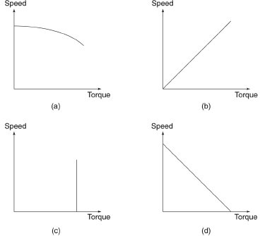
108. If the armature of a DC motor is supplied from a constant current source and its fi eld fed from a constant voltage source, then the torque-speed characteristics of the motor will be
109. Consider the following statements:
- In a DC series generator, the full-load voltage is more than the no-load voltage.
- In a separately excited DC generator, the full-load voltage is more than the no-load voltage.
- In a DC shunt generator, the full-load voltage is less than the no-load voltage.
Of these statements:
- (a) i, ii and iii are correct
- (b) i and ii are correct
- (c) ii and iii are correct
- (d) i and iii are correct
110. The armature resistance of a six pole lap wound DC machine is 0.05 Q. If the armature is rewound using a wave winding, the armature resistance will be
- (a) 0.45 Ω
- (b) 0.30 Ω
- (c) 0.15 Ω
- (d) 0.10 Ω
111. To obtain steady arc in arc welding, one should use
- (a) DC series generator
- (b) DC shunt generator
- (c) DC differentially compounded generator
- (d) DC cumulatively compounded generator
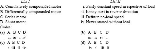
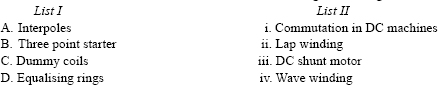
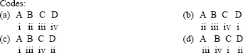
112. Match List I (DC motor) with List II (characteristics) and select the correct answer using the codes given below:
113. A belt-driven cumulative compounded DC generator is delivering power to the DC mains. If the belt snaps, then the machine will run as
- (a) cumulative compounded motor in the same direction
- (b) differentially compounded motor in the same direction
- (c) cumulative compounded motor in the opposite direction
- (d) differentially compounded motor in the opposite direction
114. For a p-pole machine, the relation between electrical (6 ) and mechanical ( 9 ) degrees is given by
![]()
115. If the field winding of an unloaded DC shunt motor gets opened while running, it will
| (a) stop | (b) run with reduced speed |
| (c) run with increased speed | (d) race |
116. List I shows the record of terminal voltage of a 10 kW, 220 V. 1,440 rpm DC shunt generator is being run at rated speed, obtained with field circuit switch open as well as closed. List II gives the possible reasons. Match List I with List II and select the correct answer using the codes given below the list:
117. A DC cumulatively compounded motor delivers rated load torque at rated speed. If the series field is short circuited, then the armature current and speed will
| (a) both decrease | (b) both increase |
| (c) increase and decrease, respectively | (d) decrease and increase, respectively |
118. A separately excited DC machine, having an armature resistance of 2 Ω was working on a 220 V supply and drawing 10 A armature current from the source when the supply voltage suddenly drooped to 200 V. Assuming that the field circuit source voltage remained unaffected, how will the armature current of the machine react to the change?
- (a) It will initially rise to 11 A and then settle down to 10 A.
- (b) It will fall momentarily to 0.09 A and then slowly attain 10 A.
- (c) It will reduce to zero first and then settle back to 10 A.
- (d) It will remain unaffected by the change and continue to be 10 A.
119. A DC cumulatively compounded generator was operating supplying power satisfactorily to an infinite bus when the mechanical power supply from the prime mover failed. The machine will then run as a
- (a) differentially compounded motor with speed reversed
- (b) differentially compounded motor with the direction of speed the same as before
- (c) cumulatively compounded motor with the same direction of speed as before
- (d) cumulatively compounded motor with speed reversed
120. In DC machines, the field system has to be provided on stator unlike synchronous machines wherein it could be on any member, because
- (a) it reduces field structure iron losses
- (b) it gives more uniform air-gap flux distribution
- (c) commutator action is not possible otherwise
- (d) DC machines are comparatively low rating
121. In a DC generator operating on load with its brushes on the geometrical neutral axis (GNA), the magnetic neutral axis (MNA) is shifted in the direction of rotation. Now if the brushes are given a lead of 90° (electrical), then the MNA will
- (a) shift forward by 90°
- (b) shift forward by more than 90°
- (c) shift forward by less than 90°
- (d) coincide with the GNA
122. A bipolar DC machine with interpoles has a main-pole flux of p per pole and an interpole flux of p. per pole. The yoke of the machine is divided into four quadrants by the main-pole axis and the commutation axis The flux distribution in the quadrants will be
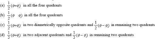
123. A cumulatively compounded DC motor runs at 1,000 rpm at no-load. On full load, the flux increases by 10 per cent, whereas the full-load drop in the combined resistance of the armature and series field is 5 per cent. Neglecting magnetic saturation, the full-load speed will be nearly
- (a) 863 rpm (b) 909 rpm (c) 1,000 rpm (d) 1,050 rpm
124. A DC overcompound generator is supplying power to an infinite bus. If the prime mover is accidentally cut-off, the DC machine will
- (a) stop running
- (b) run as cumulatively compounded motor in the reverse direction
- (c) run as differentially compounded motor in the reverse direction
- (d) run as differentially compounded motor in the same direction
125. A DC shunt motor is run under the following conditions:
- Normal voltage with no additional resistance in armature or field circuits.
- 50 per cent normal voltage with no additional resistance in armature or filed circuits.
- Normal voltage with a small external resistance in the armature circuit of a value equal to the armature resistance.
- Normal voltage with a high resistance in series with the field winding.
The speed of the motor would increase in the sequence
- (a) i, ii, iii and iv
- (b) i, iv, iii and ii
- (c) ii, i, iv and iii
- (d) ii, iii, i and iv
126. The residual magnetism of a self-excited DC generator is lost. To build up its emf again
- (a) the field winding must be replaced
- (b) the armature connection must be reversed
- (c) the field winding connection must be reversed
- (d) field winding must be excited by low-voltage DC supply
127. The magnetic circuit of a DC generator with negligible armature resistance and brush contact voltage drop remains unsaturated when it delivers full-load terminal current at rated terminal voltage. The brushes are kept in the interpolar axis and speed is maintained constant. When the load is switched off, the terminal voltage would
- (a) remain the same
- (b) increase
- (c) decrease
- (d) become zero
128. Under which of the following conditions is a DC motor provided with compensating winding used?
- Wide range of speed control above normal
- Wide range of steady load variation with no speed control
- Wide range of rapid variation in load
Select the correct answer using the codes given below:
- (a) i, ii and iii (b) ii and iii (c) i and ii (d) i and iii
129. Match List I with List II and select the correct answer using the codes given below the lists:
130. A four-pole dynamo with wave wound armature has 51 slots containing 20 conductors in each slot. The induced emf is 357 V and the speed is 8,500 rpm. The flux per will be
- (a) 3.5 mWb (b) 1.2 mWb (c) 1.4 mWb (d) 21 mWb
131. Out of the following factors for a DC machine
| i. interpole | ii. armature resistance |
| iii. armature reactance | iv. reduction in field current |
| v. reduction in field current |
The factors that are responsible for decrease in the terminal voltage of a shunt generator are
| (a) i, ii and iv | (b) ii, iii and iv |
| (c) iii, iv and v | (d) ii, iv and v |
132. In a DC generator, the windage loss is proportional to
| (a) supply voltage | (b) square of supply voltage |
| (c) square of armature current | (d) flux density |
133. Out of the following losses in a DC machine, which one has the highest proportion?
| (a) armature copper loss | (b) field copper loss |
| (c) hysteresis loss | (d) eddy current loss |
134. A shunt generator running at 1,000 rpm has induced emf at 200 V. If the speed increases to 1,200 rpm, the induced emf will be nearly
| (a) 150 V | (b) 175 V |
| (c) 240 V | (d) 290 V |
135. The yoke of a DC generator is usually made of
| (a) cast iron | (b) copper |
| (c) stainless steel | (d) silicon steel |
136. What will happen if a 220 V DC series motor is connected to 230 V AC supply?
- (a) The armature winding of motor will burn.
- (b) The motor will vibrate violently.
- (c) The motor will run with less efficiency and more sparking.
- (d) The motor will not run.
137. In a DC machine, the dummy coils of wave winding are differentiated from other coils by
| (a) their thickness | (b) their length |
| (c) the tapped ends of conductor | (d) none of the above |
138. Two similar shunt machines are changed to compound machines. If machine A is wound with twice as many series field turns per pole as machine B, then
- (a) machine A will have lesser speed change with load than that of B
- (b) machine A will have greater speed change with load than that of B
- (c) machine A will have equal speed change with load than that of B
- (d) none of the above
139. In series/parallel control of DC series motors
- (a) speed in series arrangement is four times the speed in parallel arrangement
- (b) speed in series arrangement is one-fourth times the speed in parallel arrangement
- (c) speed in series arrangement is double the speed in parallel arrangement
- (d) speed in series arrangement is half of the speed in parallel arrangement
140. Multiplex lap winding is used
- (a) to reduce commutation difficulties
- (b) to increase voltage of machine
- (c) to increase number of parallel paths
- (d) to reduce armature reaction effect
141. A series motor is working drawing a load current of 1 A from the lines. If the load is reduced such that the current drawn is halved, the speed of the machine (neglecting saturation and armature resistance) would be
| (a) unchanged | (b) reduced by 50% |
| (c) reduced by 100% | (d) increased by 100% |
142. A cumulatively compound DC generator is supplying 20 A and 200 V. Now if the series field winding is short circuited, the terminal voltage will
| (a) remain unaltered at 200 V | (b) rise to 220 V |
| (c) shoot up to a high value | (d) will reduce to 150 V |
143. A DC armature having 1,152 lap-connected conductors carrying 120 A rotates at 2,500 rpm. If the machine has 12-pole field with flux per pole 0.075 Wb, the power output of the armature will be
- (a) 21.5 kW (b) 43 kW (c) 86 kW (d) 172 kW
144. DC series motors are preferred to traction due to
| (a) continuous long runs | (b) near full load operation |
| (c) high starting torque | (d) high efficiency and low cost |
145. A DC generator can be termed as
- (a) rotating amplifier (b) prime mover (c) power pump (d) booster
146. If A be the commercial efficiency, B the electrical efficiency and C the mechanical efficiency of a DC generator then which of the following relations is valid?
- (a) A = B × C (b) B = A × C (c) C = A × B (d) C = A + B
147. The material used for brushes in 220 V DC machine is
- (a) aluminium (b) carbon (c) electrographite (d) copper-carbon
148. Hysteresis loss in a DC machine is proportional to
- (a) 1/N (b) N (c) N2 (d) 1/N2
149. Brushes in DC machines are always placed along:
| (a) geometrical neutral axis | (b) magnetic neutral axis |
| (c) perpendicular to GNA | (d) perpendicular to MNA |
150. In lap winding of a DC machine, equaliser rings are used to avoid
- (a) unequal contribution of current at the brushes resulting in sparkless commutation
- (b) noise developed in the machine
- (c) harmonics and eddy currents in windings
- (d) short circuit conditions of the closed machine
151. Commutation may be improved by
- (a) reducing the number of turns in armature and segments of commutator
- (b) increasing the resistance of brushes
- (c) neutralizing the reactance voltage by producing a reverse emf in the coil undergoing commutator
- (d) all of these
152. The maximum number of equalizer rings needed in an electrical machine equals:
153. The factor that does not cause decrease in the terminal voltage of a DC shunt generator is
| (a) armature resistance | (b) armature reactance |
| (c) reduction in field current | (d) none of these |
154. If instead of DC voltage, an AC voltage is applied on to the field of a DC generator then the output of DC generator
| (a) will be AC voltage | (b) will be DC voltage |
| (c) will be zero | (d) machine will burn out |
155. Speed of a DC shunt motor is proportional to
- (a) Ia/2 (b)I/Ia (c) Ia (d) independent of Ia
156. Two DC series motors connected in series draw current I from the supply and run at a speed N. When the same motors are connected in parallel taking current I from the supply, the speed of each motor will be
- (a) N (b) 2N (c) 4N (d) N/2
157. A cumulative compound DC motor runs at 1,500 rpm on full load. If the series field is short circuited, its speed
| (a) becomes zero | (b) remains unchanged |
| (c) increases | (d) decreases |
158. Regenerative breaking is used only when the load has
| (a) a small value | (b) retarding motion |
| (c) an overhauling characteristic | (d) none of the above |
159. Neglecting all losses, the developed torque (T) of a DC separately excited motor, operating under constant terminal voltage, is related to its output power (P) as under
- (a) T °°VP (b) T °° P (c) T2 °° P3 (d) T independent of P
160. A separately excited DC motor has an armature resistance of 0.5. It runs off a 250 V DC supply drawing an armature current of 20 A at 1,500 rpm. The torque developed for an armature current of 10 A will be for the same field current
- (a) 15 Nm (b) 30 Nm (c) 45 Nm (d) 90 Nm
161. Assertion A: A differentially compound DC motor has the possibility of starting in the reverse direction.
Assertion B: Owing to higher inductance in the series field, the resultant main flux reverses during starting.
Mark the answer
- (a) Both A and B are true and B is the correct explanation of A.
- (b) Both A and B are true but B is not the correct explanation of A.
- (c) A is true but B is false.
- (d) A is false but B is true.
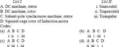
162. Match List I (parts of electrical machines) with List II (the approximate nature of the air-gap mmf pattern produced by them) and select the correct answer using the codes given below the list:
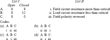
163. A DC shunt generator, when driven at its rated speed, is found to be not generating any voltage. Which of the following would account for this?
- There is no residual magnetism.
- The connection of the field winding is not proper with respect to the armature.
- The resistance of the field circuit is greater than the critical resistance.
- The load resistance is less than the critical armature resistance.
Codes:
| (a) iii and iv | (b) i, ii and iv |
| (c) i, ii and iii | (d) i, ii, iii and iv |
164. To have sparkles commutation, the armature reaction effect in a DC machine is neutralized by
- (a) using compensating winding and commutating poles
- (b) shifting the brush axis from the geometrical neutral axis to the magnetic neutral axis
- (c) fixing the brush axis in line with the poles
- (d) increasing the field excitation
165. In a DC shunt generator working on load, the brushes are moved forward in the direction of rotation. As a result of this, commutation will
- (a) improve but terminal voltage will fall
- (b) worsen and terminal voltage will fall
- (c) improve and terminal voltage will rise
- (d) worsen and terminal voltage will rise
166. A DC over-compounded generator was operating satisfactorily and supplying power to an infinite bus when the prime mover failed to supply any mechanical power. The machine would then run as a
- (a) cumulatively compounded motor with speed reversed
- (b) cumulatively compounded motor with direction of rotation as before
- (c) differentially compounded motor with speed reversed
- (d) differentially compounded motor with direction of speed as before
167. If a 230 V DC series motor is connected to a 230 V AC supply
- (a) motor will vibrate violently
- (b) motor will run less with less efficiency and more sparking
- (c) motor will not run
- (d) fuse will be blown
168. The interpoles in DC machines have a tapering shape in order to
- (a) reduce the overall weight
- (b) reduce the saturation in the interpole
- (c) economise on the material required for interpoles and their windings
- (d) increase the acceleration of commutation
169. Consider the following statements:
| i. Sparking at brushes | ii. Acceleration time |
| iii. Starting current | iv. Voltage dip in supply |
Of these statements:
| (a) i and ii are correct | (b) ii, iii and iv are correct |
| (c) i, iii and iv are correct | (d) i, ii, iii and iv are correct |
170. As compared to the use of a single series DC motor for electric traction for a given starting time t, the series-parallel control using two similar motors with time t/2 for each series and parallel operation would give a saving in starting energy of
- (a) 100% (b) 50% (c) 25% (d) zero
171. Consider the following statements:
Permanent magnet DC motors used in cassette tape recorders have
- magnets on stator and armature on the rotor
- magnets on the rotor and armature on the stator
- electronic commutation and no brushes
- mechanical commutation and brushes
- automatic speed governors
Of these statements:
| (a) i, iii and v are correct | (b) i, iv and v are correct |
| (c) ii, iii and v are correct | (d) i and iv are correct |
172. The compensating winding in a DC machine
- (a) is located in armature slots for compensating of the armature
- (b) is located on commutating poles for improving the commutation
- (c) is located on pole shoes for avoiding the flashover at the commutator surface
- (d) is located on pole shoes to avoid the sparking at the brushes
173. A 240 V DC series motor takes 40 A when giving its rated output at 1,500 rpm. Its resistance is 0.3 Ω. The value of resistance that must be added to obtain rated torque at 1,000 rpm is
- (a) 6 Ω (b) 5.7 Ω (c) 2.2 Ω (d) 1.9 Ω
174. A permanent magnet DC commutator motor has a no load speed of 6,000 rpm when connected to a 120 V DC supply. The armature resistance is 2.5 Ω and other losses may be neglected. The speed of the motor with supply voltage of 60 V developing a torque 0.5 Nm is
| (a) 3,000 rpm | (b) 2,673 rpm |
| (c) 2,836 rpm | (d) 5,346 rpm |
175. An electric motor with constant output power will have a torque-speed characteristic in the form of
- (a) straight line through the origin
- (b) straight line parallel to the speed axis
- (c) circle about the origin
- (d) rectangular hyperbola
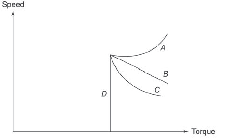
176. A DC series motor fed from rated supply voltage is overloaded and its magnetic circuit is saturated. By which curve of Figure 3 will the torque-speed characteristic of this motor be approximately represented?

Figure 3
- (a) Curve A (b) Curve B (c) Curve C (d) Curve D
177. A 200 V, 2,000 rpm, 10 A, separately excited cDC motor has an armature resistance of 2 Ω. Rated DC voltage is applied to both the armature and field winding of the motor. If the armature draws 5 A from the source, the torque developed by the motor is
- (a) 4.30 Nm (b) 4.77 Nm (c) 0.45 Nm (d) 0.50 Nm
178. Two 550 kVA alternators operate in parallel to supply the following loads:
- 250 kW at 0.95 pf lagging
- 100 kW at 0.85 pf lagging
One machine is supplying 200 kW at 0.9 pf lagging. The pf of other machine must be
- (a) 0.89 leading (b) 0.95 leading (c) 0.95 lagging (d) 0.89 lagging
179. Match List I with List II and select the correct answer using the codes given below the lists:
180. The most appropriate operating speed in rpm of generators used in thermal, nuclear and hydro plants would, respectively, be
| (a) 3,000, 300 and 1,500 | (b) 3,000, 3,000 and 300 |
| (c) 1,500, 1,500 and 3,000 | (d) 1,000, 900 and 750 |
181. A large AC generator supplying power to an infinite bus has a sudden short circuit occurring at its terminals. Assuming the prime mover input and the voltage behind the transient reactance to remain constant immediately after the fault, the acceleration of the generator rotor is
- (a) inversely proportional to the moment of inertia of the machine
- (b) inversely proportional to the square of the voltage
- (c) directly proportional to the square of the short circuit current
- (d) directly proportional to the short circuit power
182. The fifth harmonic component of the induced voltage in three-phase AC generator can be entirely eliminated by using a winding pitch of
- (a) 2/3 (b) 4/5 (c) 5/6 (d) 6/7
183. Which of the following limit the reactive power output of a synchronous generator?
| i. Armature current | ii. Field current |
| iii. Load angle | iv. Prime mover |
Select the correct answer using the codes given below: Codes:
- (a) i and ii (b) ii and iii (c) iii and iv (d) i and iv
184. During the slip-test for determining the direct and the quadrature axis synchronous reactance of an alternator, the voltage across the open field circuit terminals is
- (a) DC voltage
- (b) AC voltage of supply frequency
- (c) AC voltage of slip frequency
- (d) a modulated voltage
185. A three-phase fault occurs at the terminals of an unloaded alternator at an instant when the AC component in one phase is at its maximum value. The variation in DC component during fault period in that phase will depend upon
- (a) subtransient time constant
- (b) transient time constant
- (c) open-circuit time constant
- (d) armature time constant
186. Which one of the following motors running under the specified conditions will have a leading power factor?
- (a) slip ring induction motor at no load
- (b) under-excited synchronous motor
- (c) over-excited synchronous motor
- (d) double-cage induction motor at load
187. A synchronous machine working in the motor mode is fed from an infinite bus and is delivering half of full-load. If an increase in field current causes an increase in the armature current, then the motor will
- (a) deliver reactive power and active power to the bus
- (b) absorb reactive power and active power from the bus
- (c) absorb reactive power from the bus and deliver active power to the bus
- (d) absorb reactive power to the bus and deliver active power from the bus
188. The voltage across the open-circuited field terminals of a synchronous machine under slip test is
- (a) DC
- (b) AC of slip frequency
- (c) a modulated supply frequency AC voltage with slip frequency envelope
- (d) AC of supply frequency
189. Two three-phase AC generators are such that one has twice the linear dimensions of other. The field windings of each are excited to give identical sinusoidal air-gap flux density waveform. Both have the same number of stator slots and identical winding patterns. The conductor/slot in big generator is K times that of the smaller one. The value of K to get equal no-load voltage at the same frequency is
- (a) 8 (b) 4 (c) 1/2 (d) 1/4
190. A three-phase and four-pole alternator has 48 stator slots carrying the three-phase distributed winding. Each coil of the winding is short chorded by one slot pitch. The winding factor is given by
![]()
191. A three-phase synchronous motor connected to infinite bus is operating at half of full-load with normal excitation. When the load on the synchronous motor is suddenly increased,
- (a) its speed will first decrease and then become synchronous
- (b) its speed will first increase and then become synchronous
- (c) its speed will fluctuate around synchronous speed and then become synchronous
- (d) its speed will remain unchanged
192. Two mechanically coupled alternators deliver power at 50 Hz and 60 Hz, respectively. The highest speed of the alternators is
- (a) 3,600 rpm (b) 3,000 rpm (c) 600 rpm (d) 500 rpm
193. When a balanced three-phase distributed-type armature winding is carrying three-phase, balanced currents, the strength of the resultant rotating magnetic field is
- (a) three times the amplitude of each constituent pulsating magnetic field
- (b) equal to the amplitude of each constituent pulsating magnetic field
- (c) half the amplitude of each constituent pulsating magnetic field
- (d) one and a half times the amplitude of each constituent pulsating magnetic field
194. An alternator is capable of delivering power at a particular frequency. The frequency can be increased by
- (a) increasing the current supplied to the electromagnetic field
- (b) reversing the armature rotation
- (c) increasing armature speed
- (d) reversing field polarity
195. The simplest way to eliminate the harmonic induction torque is
| (a) integral slot winding | (b) skewing |
| (c) chording | (d) none of the above |
196. For an alternator when the power factor of the load is unity,
| (a) armature flux will have square waveform | (b) armature flux will be demagnetising |
| (c) armature flux will be cross-magnetising | (d) armature flux will reduce to zero |
197. The driving power from the prime mover driving the alternator is lost but the alternator remains connected to the supply network and the field supply remains on. The alternator will
- (a) get burnt
- (b) behave as an induction motor but will rotate in the opposite direction
- (c) behave as a synchronous motor but will rotate in the same direction
- (d) behave as a synchronous motor but will rotate in a reverse direction to that corresponding to generator action
198. If the input of the prime mover of an alternator is kept constant but the excitation is changed, then
- (a) active component of the output is changed
- (b) reactive component of the output is changed
- (c) power factor of the load remains constant
- (d) power factor of the load changes from lagging to leading
199. An exciter for a generator is
- (a) series motor (b) shunt motor (c) series generator (d) shunt generator
200. When two alternators are running in parallel, their kVAR load share is changed by changing their while their kW load share is changed by changing their
| (a) excitation, driving torque | (b) driving torque, excitation |
| (c) excitation, excitation | (d) driving torque, driving torque |
201. The Potier's triangle separates
- (a) iron losses and copper losses
- (b) field mmf and armature mmf
- (c) stator voltage and rotor voltage
- (d) armature leakage reactance and armature reaction mmf
202. Alternators used in aircraft systems usually have frequency of
- (a) 25 Hz (b) 50 Hz (c) 100 Hz (d) 400 Hz
203. Two alternators A and B are sharing a resistive load (pf is unity) equally. Now if the excitation of alternator A is increased,
- (a) alternator A will become lagging and alternator B will become leading
- (b) alternator A will become leading and alternator B will become lagging
- (c) both alternators will continue to operate on unity power factor
- (d) both alternators will operate on lagging power factor
204. The advantage of providing damper winding in alternators is
- (a) elimination of harmonic effects
- (b) provide low resistance path for the currents to unbalancing of voltage
- (c) oscillations are provided when two alternators operate in parallel
- (d) all of the above
205. In a synchronous machine, if the field flux is ahead of the armature field axis, in the direction of rotation, the machine working as
| (a) asynchronous motor | (b) asynchronous generator |
| (c) synchronous motor | (d) synchronous generator |
206. In a synchronous generator, which of the following will have emf close to sine waveform?
| (a) concentrated winding in full pitch coils | (b) concentrated winding in short pitch coils |
| (c) distributed winding in full pitch coils | (d) distributed winding in short pitch coils |
207. The effect of cross magnetising in an alternator is to make the output
- (a) true sinusoidal (b) non sinusoidal (c) harmonic free (d) none of these
208. Synchronising torque comes into operation in all the cases except
- (a) phase difference between two voltages
- (b) frequency difference between two voltages
- (c) voltage difference between two voltages
- (d) reduction in excitation current in one of the alternators
209. The advantage of using short-pitched windings in an alternator is that it
- (a) suppresses the harmonics in generated emf
- (b) reduces the total voltage around the armature coils
- (c) saves copper used in windings
- (d) improves cooling by better circulation of air
210. For the same power rating, an alternator operating at lower voltage will be
- (a) less noisy (b) costlier (c) larger in size (d) more efficient
211. Salient pole-type rotors as compared to cylindrical type rotors are
- (a) smaller in diameter and larger in axial length
- (b) larger in diameter and smaller in axial length
- (c) smaller in diameter and larger in axial length
- (d) larger in diameter and larger in axial length
212. When a generator designed for operation at 60 Hz is operated at 50 Hz, then
- (a) the operating voltage must be derated to (50/60) of the original voltage
- (b) the operating voltage must be derated to (50/60)2 of the original voltage
- (c) the kVA rating can be upgraded to (60/50) of the rated value
- (d) generator will not take any load
213. The maximum power developed in the synchronous motor will depend on
- (a) rotor excitation only
- (b) maximum value of coupling angle
- (c) supply voltage only
- (d) rotor excitation supply voltage and maximum value of coupling angle
214. An overexcited synchronous motor draws current at
| (a) lagging power factor | (b) leading power factor |
| (c) unity power factor | (d) depends on the nature of the load |
215. If a synchronous motor drops too far behind, the power it takes from the supply also increases too much, and the armature tries to get accelerated, until it is in correct position. Sometimes, some motor overshoots the marks and then the process of acceleration-retardation continues. This phenomenon is known as
- (a) synchronization (b) hunting (c) pulling out (d) swinging
216. In case of a synchronous motor we have:
- load
- speed
- DC excitation
The magnitude of stator back emf depends on
| (a) i only | (b) i and ii only |
| (c) iii only | (d) i, ii and iii only |
217. The breakdown torque of a synchronous motor varied as
| (a) 1/(applied voltage) | (b) 1/(applied voltage)2 |
| (c) applied voltage | (d) (applied voltage)2 |
218. Hunting in a synchronous motor cannot be due to
| (a) variable frequency | (b) variable load |
| (c) variable supply voltage | (d) windage friction |
219. A high starting torque synchronous motor has
| (a) simplex rotor | (b) phase wound damper |
| (c) five slip rings | (d) all of the above |
220. The parameters connected with the operation of a synchronous motor are
- speed
- power factor
- armature current
When the excitation of the motor is varied, which parameters vary along with it
| (a) i only | (b) ii only |
| (c) ii and iii only | (d) i, ii and iii only |
221. The negative-phase sequence in a three-phase synchronous motor exist when
- (a) motor is overloaded (b) motor is underloaded (c) unbalanced voltage is supplied (d) motor armature is hot
222. If a synchronous motor fails to pull into synchronism after supplying DC field current, the probable cause may be
- (a) high core losses
- (b) low field current
- (c) high field current
- (d) low short circuit ratio
223. In a synchronous machine in case the axis of field flux is in line with the armature flux, then
- (a) machine is working as synchronous motor
- (b) machine is working as synchronous generator
- (c) machine is said to be floating
- (d) machine will vibrate violently
224. If other factors remain constant, the speed of a synchronous motor in its operating (and load) range is correctly described by which of the following?
- (a) The speed varies directly only in proportion to the number of poles.
- (b) The speed is independent of the frequency of the voltage supply.
- (c) The speed depends on the frequency of the voltage supply and the number of poles.
- (d) The speed depends on the magnitude of the voltage supply and the number of its pole
225. While starting the synchronous motor by induction motor action, very high emf is induced in the field. This induced emf may damage the insulation of the field winding and the slip rings. The insulation damage can be prevented by
- (a) short circuiting the field winding by field discharge resistance
- (b) splitting the field winding into several sections
- (c) either of (a) or (b)
- (d) none of the above
226. The construction of a synchronous motor resembles which of the following machines?
| (a) induction motor | (b) rotor converter |
| (c) alternator | (d) series motor |
227. The rotor of a synchronous motor can only run at synchronous speed of the stator magnetic field due to
- (a) Faraday's law of electromagnetic induction
- (b) Lenz's law
- (c) magnetization of rotor poles by stator magnetic field
- (d) interlocking action between stator and rotor fields
228. An inverted V-curve of a synchronous motor is the variation of
- (a) field current and DC excitation of constant load
- (b) supply voltage and field current at constant excitation
- (c) power factor and supply voltage during hunting
- (d) supply voltage and excitation current at constant load
229. Damper windings are provided on
| (a) pole faces | (b) separate armature |
| (c) rotor shaft | (d) stator frame |
230. When a synchronous motor is running at synchronous speed, the damper winding produces
| (a) damping torque | (b) eddy current torque |
| (c) torques aiding the developed torque | (d) no torque |
231. In a synchronous generator, a divided winding rotor is preferable to a conventional winding rotor because of
| (a) higher efficiency | (b) increased steady state stability limit |
| (c) higher short circuit current | (d) better damping |
232. The per-unit impedance of a synchronous machine is 0.242. If the base voltage is increased by 1.1 times, the per-unit value will be
- (a) 0.266 (b) 0.242 (c) 0.220 (d) 0.200
233. If the dimensions of all the parts of a synchronous generator, and the number of field and armature turns are doubled, then the generated voltage will change by a factor of
- (a) 1 (b) 2 (c) 4 (d) 8
234. Consider the following statements:
The effects of slot harmonics are effectively reduced by
| i. skewing the slots | ii. fractional slot winding |
| iii. short-chorded winding | iv. distributed winding |
Of these statements
| (a)i and ii are correct | (b)i, iii and iv are correct |
| (b)ii, iii and iv are correct | (d)i and iii are correct |
235. Which of the following methods would give a higher than actual value of regulation of an alternator?
- (a) ZPF method (b) MMF method (c) EMF method (d) ASA method
236. A turbo alternator set feeds power to a three-phase constant-voltage, constant-frequency bus. If the steam supply to the set is cut off, then the set will
- (a) continue to run at rated speed in the same direction
- (b) continue to run at reduced speed in the same direction
- (c) run at rated speed in reverse direction
- (d) come to stop
237. An ideal synchronous motor has no starting torque because the
- (a) rotor is made up of salient poles
- (b) relative velocity between the stator and rotor mmfs is zero
- (c) relative velocity between the stator and rotor mmfs is not zero
- (d) rotor winding is highly reactive
238. Electrical machines are generally designed to have maximum efficiency
- (a) no load (b) 50% load (c) near about full load (d) full load
239. Which of the following statements are true?
- High-speed alternators usually have salient pole rotors.
- Cylindrical rotor alternators have large length-to-diameter ratio.
- Salient pole machines have large number of poles.
- To ensure proper cooling, cylindrical rotor alternators use radial ducts only.
- (a) i and ii only (b) ii and iii only (c) iii and iv only (d) i and iv only
240. Which of the following statements are true?
- A synchronous motor supplying its rated load has its excitation increased resulting in power factor becoming more lagging.
- In a synchronous motor, the rotor mmf and stator mmf are stationary with respect to each other.
- The short circuit characteristic of an alternator is always nonlinear.
- (a) i and ii only (b) ii and iii only (c) i and iii only (d) ii only
241. Consider the following statements:
- Asynchronous motor has no starting torque but when started it always runs at a fixed speed.
- Neglecting residual magnetism, both cylindrical rotor and salient pole synchronous motor produce some mechanical power even through the field is unexcited.
- A single-phase reluctance motor is not self-starting even if paths for eddy current are provided in the rotor.
- A single-phase hysteresis motor is self-starting.
Of the above statements:
- (a) Only i and ii are correct (b) Only i and iii are correct
- (c) Only ii, iii and iv are correct (d) Only i, ii and iv are correct
242. The essential conditions for running two alternators in parallel are the following:
- Terminal voltage should be same.
- Frequency should be same.
- Phase sequence should be same.
Of the above statements, which of the following options hold
- (a) i only (b) ii only (c) i and ii only (d) i, ii and iii
243. The magnitude of emf induced in the stator due to revolving flux will depend on the
- (a) speed of the motor (b) DC excitation current
- (c) load of the motor (d) speed and rotor flux
244. The magnitude of the induced emf in the stator of a synchronous motor
- (a) is equal to the supply voltage
- (b) is less than the supply voltage
- (c) can be increased than the supply voltage
- (d) can be increased or decreased than the supply voltage
245. In all cases of electromagnetic induction, an induced voltage will cause a current to flow in a closed circuit in such a direction that the magnetic field caused by that current will oppose the change that produces the current is the original statement of
- (a) Lenz's law (b) Faraday's law of magnetic induction
- (c) Fleming's law of induction (d) Ampere's law
246. A centre-zero ammeter connected in the rotor circuit of a six-pole 50 Hz induction motor makes 30 oscillations in one minute. The rotor speed is
- (a) 970 rpm (b) 990 rpm (c) 1,010 rpm (d) 1,030 rpm
247. Consider the following statements:
In a three-phase induction motor connected to a three-phase supply, if one of the lines suddenly gets disconnected, then the
- motor will come to standstill
- motor will continue to run at the same speed with line current unchanged
- motor will continue to run at a slightly reduced speed with increased line current
- rotor currents will have both sf and (2-5)/component frequencies where s is slip andf is supply frequency
Of these statements:
- (a) i and iv are correct (b) i and ii are correct
- (c) iii and iv are correct (d) ii and iii are correct
248. In a self-excited induction generator, to keep the frequency of generated voltage constant with the increase in load the speed of the induction machine should be
- (a) increased
- (b) decreased
- (c) maintained less than the rated synchronous speed
- (d) maintained more than the rated synchronous speed
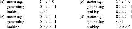
249. In a three-phase induction machine, motoring generating and braking operations take place in the range of slip ‘s’ given by
250. A voltmeter gives 120 oscillations per minute when connected to the rotor of an induction motor. The stator frequency is 50 Hz. The slip of the motor is
- (a) 2% (b) 2.5% (c) 4% (d) 5%
251. Semi-closed slots or totally closed slots are used in induction motors, essentially to
- (a) improve starting torque
- (b) increase pull-out torque
- (c) increase efficiency
- (d) reduce magnetising current and improve power factor
252. A starting torque of 80 Nm is developed in an induction motor by an auto-transformer starter with a tapping of 30 per cent. If the tapping of autotransformer starter is 60 per cent, then the starting torque will be
- (a) 40 Nm (b) 160 Nm (c) 240 Nm (d) 320 Nm
253. The torque-slip characteristic of a polyphase induction motor becomes almost linear at small values of slip, because in this range of slips
- (a) effective rotor circuit resistance is very large compared to the rotor reactance
- (b) rotor resistance is equal to stator resistance
- (c) rotor resistance is equal to the rotor reactance
- (d) rotor reactance is equal to the stator reactance
254. Breakdown torque of a three-phase induction motor of negligible stator impedance is
- (a) directly proportional to the rotor resistance
- (b) inversely proportional to the rotor resistance
- (c) directly proportional to the reactance
- (d) inversely proportional to the rotor leakage reactance
255. If a three-phase induction motor, fed from a rated-voltage and rated-frequency supply, is driven by a prime-mover in the same direction when operating as a motor, at super synchronous speed, the machine will operate as
- (a) a reactive power generator (b) a frequency converter
- (c) an active power generator (d) a rotary converter
256. A reduction of the voltage applied to a three-phase induction motor
- (a) increases the breakdown torque and the starting torque
- (b) increases the breakdown torque but decreases the starting torque
- (c) decreases the breakdown torque
- (d) decreases both breakdown and starting torque
257. Consider the following statements regarding the equivalent circuit parameters of an induction motor:
- Leakage reactance is dependent on supply current.
- Magnetizing reactance is dependent on the air-gap flux.
- Core loss is dependent on the input voltage and frequency.
- Rotor resistance is dependent on the speed.
Of these statements:
- (a) ii and iii are correct
- (b) i, iii and iv are correct
- (c) i, ii, iii and iv are correct
- (d) i, ii and iv are correct
258. Crawling of an induction motor is due to
- (a) space harmonics in the stator flux
- (b) the number of teeth on stator being equal to the number of teeth on the rotor
- (c) the fluctuation in load torque
- (d) unequal distribution of winding
259. A three-phase induction machine operates on three-phase fixed frequency AC mains at a slip of 1.5. Consider the following statements:
- It draws electrical power from the mains.
- It draws the mechanical power from the mains.
- It delivers electrical power to the mains.
- It delivers mechanical power to the mains.
Of these statements:
- (a) i and ii are correct (b) i and iv are correct
- (c) ii and iii are correct (d) iii and iv are correct
260. The magnetising current component of the no-load current of an induction motor is much larger than a corresponding transformer because of
- (a) additional friction and windage loss in motor
- (b) different winding configuration on stator and rotor
- (c) increased flux requirement
- (d) an air-gap in the magnetic circuit
261. The rotor of a four-pole, three-phase cage induction motor is replaced by a three-phase, four-pole wound rotor. When fed with normal supply, the machine will
- (a) not run (b) run at very low speed
- (c) run at slightly lower than normal speed (d) run at slightly higher than normal speed
262. A three-phase induction motor operates on a variable frequency, variable voltage supply such that V/f is constant. The breakdown torque of the drive will
- (a) decrease with decrease with frequency
- (b) remain constant irrespective of the frequency
- (c) be slightly lower at very low frequencies
- (d) increase with decrease in frequency
263. The stator of a 415 V, 50 Hz, six-pole, 970 rpm three-phase slip ring induction motor is fed with normal voltage. The rotor with slip rings open-circulated is rotated at 500 rpm along the normal direction of its rotation. The frequency of the voltage across slip rings will be
- (a) 15 Hz (b) 25 Hz (c) 26.5 Hz (d) 75 Hz
264. Which class of insulating materials can withstand maximum temperature?
- (a) A class (b) B class (c) C class (d) E class
265. Which of the following induction motors will have the least shaft diameter?
- (a) 20 HP, 2,880 rpm (b) 20 HP, 1,440 rpm (c) 20 HP, 960 rpm (d) 20 HP, 730 rpm
266. An induction motor is
- (a) self-starting with zero torque
- (b) self-starting with very high torque
- (c) self-starting with smaller torque
- (d) none of the above
267. An induction motor will take least starting current when
- (a) directly switched on
- (b) started by reactance starter
- (c) started by autotransformer with minimum of 65 per cent tapping
- (d) started by star-delta starter
268. A 20 kW, four-pole, 400 V, 60 Hz, three-phase, 1,728 rpm induction motor is connected to 400 V, 50 Hz supply. The motor will
- (a) not run (b) burn out
- (c) run at more than 1,720 rpm (d) run at less than 1,720 rpm
269. A four-pole, three-phase induction motor is running at 4 per cent slip at full load. If the speed of the motor is 720 rpm, the supply frequency is 2
![]()
270. When the supply voltage of an induction motor is increased by 10 per cent, the maximum running torque will
- (a) remain unaltered (b) increase by about 10 per cent
- (c) increase by 20 per cent (d) decrease by about 10 per cent
271. When a three-phase induction motor is loaded,
- (a) induced emf in the rotor decreases and its frequency increases
- (b) induced emf on the rotor increases and its frequency falls
- (c) induced emf in the rotor as well as frequency falls
- (d) induced emf in the rotor as well as frequency increases
272. Squirrel cage induction motor has
- (a) zero starting torque (b) very small starting torque
- (c) medium starting torque (d) very high starting torque
273. In an induction motor, rotor slots are usually not quite parallel to the shaft but are given a slight skew for the following reasons:
- (a) to reduce the magnetic hum
- (b) to reduce the locking tendency of the rotor
- (c) to reduce the locking tendency and the magnetic hum
- (d) to increase the speed of the rotor
274. The purpose of blades in squirrel cage induction motor is
- (a) to reduce the magnetic resistance of the rotor
- (b) to cool the rotor
- (c) to reduce the electrical resistance of the rotor cage
- (d) none of the above
275. In the following motor, external resistance can be added to start the motor
- (a) slip ring induction motor (b) squirrel cage induction motor
- (c) salient pole synchronous motor (d) wound rotor synchronous motor
276. Torque developed by three-phase induction motor equals
- (a) copper losses in the rotor (b) gross mechanical power developed
- (c) air-gap power transferred to rotor (d) power input to rotor minus rotor losses
277. When an induction motor runs at rated load and rated speed, the iron losses are
- (a) negligible (b) very high
- (c) independent of supply frequency (d) independent of supply voltage
278. The starting torque of an induction motor is maximum when
- (a) rotor resistance equals to rotor reactance
- (b) rotor resistance is twice the rotor reactance
- (c) rotor resistance is half the rotor reactance
- (d) rotor resistance is a/2 times rotor reactance
279. Improvement of power factor in an induction motor results in
- (a) decreased torque
- (b) increased torque
- (c) increased current
- (d) increased torque and decreased current due to increased impedance
280. For smooth starting of three-phase squirrel-cage induction motor, the following starting method is preferred:
- (a) rotor resistance (b) star-delta (c) autotransformer (d) stator resistance
281. The low power factor of an induction motor at low load results in
- (a) high speed (b) low magnetising component of I0
- (c) high magnetising component of I0 (d) high working component of I9
282. The three-phase induction motor is mainly suitable for following applications:
- (a) for running different machine tools where several speeds are required
- (b) for running paper machine requiring exact speed control
- (c) for running electric vehicles
- (d) for running rolling mills needing exact speed control
283. Any odd harmonics in the current of an induction motor will result in magnetic field, which
- (a) oscillates at harmonics frequency
- (b) rotates in backward direction
- (c) rotates in forward direction at the harmonic speed
- (d) is stationary relative to the field of the fundamental
284. The number of different speeds that can be obtained from two induction motors in cascade is
- (a) 2 (b) 3 (c) 4 (d) 6
285. The efficiency of induction motor X is 90 per cent and that of Y is 80 per cent. The size of motor X is
- (a) larger than Y (b) equal to Y
- (c) smaller than Y (d) may be either larger or smaller
286. Imbalance in the shaft of an induction motor occurs due to
- (a) slip rings (b) overheating of winding
- (c) non-uniform air gap (d) rigid construction
287. Negative sequence currents are set up in an induction motor when
- (a) bearing friction is more (b) windage losses are excessive
- (c) air gap is more (d) unbalanced three-phase supply is given
288. For a 60-HP motor, which type of rotor will be preferred?
- (a) wound rotor
- (b) squirrel cage rotor using round copper bars
- (c) squirrel cage rotor using rectangular copper bars
- (d) die-casted aluminium rotor
289. Two slip-ring induction motors having number of poles as P1 and P2, respectively, are connected in cascade. If the supply frequency is f, the speed of the main motor will be
![]()
290. A three-phase induction motor takes A amperes on full load at a power factor cos p. The main component responsible for producing magnetism is
- (a) A sin p (b) A cos p (c) A tan p (d) A/cos p
291. The stator of a three-phase, four-pole wound rotor induction motor is connected to 50 Hz source but its rotor is energised from 20 Hz source. The two no-load speeds of the motor will be
- (a) 1,440 rpm and 960 rpm (b) 2,100 rpm and 900 rpm
- (c) 2,400 rpm and 600 rpm (d) 1,560 rpm and 1,440 rpm
292. Following are the trouble shooting operations:
- Check the motor.
- Check the thermal overload relay.
- Check the fuses.
- Check the motor control panel.
If the motor fails to start, the correct sequence in which these checks should be carried out is
- (a) i, ii, iii and iv (b) i, iii, iv and ii (c) iii, ii, iv and i (d) ii, iv, i and iii
293. Match List I (type of winding) with List II (feature) and select the correct answer using the codes given below the list:
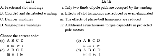
294. While conducting a ‘slip’ test for the determination of direct and quadrature-axis synchronous machine, the rotor of the machine is run with a slip ‘s’ and stator supply frequency f. The frequency of
- voltage induced across open field terminals
- envelope of the armature terminal voltage
- envelope of armature current
- armature
will be
- (a) sf, sf, sf and f respectively
- (b) sf, f sf and sf, respectively
- (c) f sf, f and f respectively
- (d) f (1-s)f, (2-s)f and sf, respectively
295. If two induction motors are identical except that the air-gap of motor ‘A’ is 50 per cent greater than that of motor ‘B', then
- (a) no-load power factor of A will be better than that of B
- (b) no-load power factor of A will be poorer than that of B
- (c) core losses of A will be more than those of B
- (d) flux of A will be smaller than that of B
296. Which of the following statements regarding skewing of motor bars in a squirrel-cage induction motor are correct?
- It prevents cogging.
- It produces more uniform torque.
- It increases starting torque.
- It reduces motor ‘hum’ during its operation.
Select the correct answer using the codes given below:
- (a) ii, iii and iv (b) i, ii and iii (c) i, ii and iv (d) i, iii and iv
297. The rotor power output of a three-phase induction motor is 15 kW and the corresponding slip is 4 per cent. The rotor copper loss will be
- (a) 600 W (b) 625 W (c) 650 W (d) 700 W
298. A three-phase induction machine draws active power ‘P’ and reactive power ‘Q’ from the grid. If it is operated as a generator, P and Q will, respectively, be
- (a) positive and negative (b) negative and negative
- (c) positive and positive (d) negative and positive
299. A three-phase induction motor fed from a three-phase voltage controller is suitable for driving loads whose torque is
- (a) constant irrespective of speed
- (b) inversely proportional to the square of the speed
- (c) directly proportional to the square of speed
- (d) inversely proportional to speed
300. A three-phase induction motor when started picks up speed but runs stably at about half the normal speed. This is because of
- (a) unbalance in the supply voltage (b) non-sinusoidal nature of supply voltage
- (c) stator circuit asymmetry (d) rotor circuit asymmetry
Answers