
7 Synchronous Motors
The details of a synchronous generator or alternator have already been introduced in Chapter 6. In synchronous generators, the field is excited by direct current and no supply is applied to armature. The rotor is rotated by the prime mover at a constant speed known as synchronous speed. Hence emf is induced in the armature. In contrast, in synchronous motor the field is excited by a direct current and stator is connected to a three-phase alternating voltage. Since the motor is rotated at a synchronous speed, it is called synchronous motor. Its speed is constant irrespective of the load. This chapter introduces the various aspects of synchronous motors.
7.1 PRINCIPLES OF OPERATION
In Figure 7.1, the coil ab carries current where conductor a carries current towards the observer and conductor b away from the observer. Therefore, a torque is developed by motor action that drives the conductor from left to right. It will reverse its direction for the next half cycle and the torque then acts from right to left for alternating current that causes the net torque to be zero over any given number of complete cycles. Hence, no continuous motion can result, and thus a synchronous motor is standstill. Therefore, the synchronous motor does not develop any starting torque.
If the conductor a is taken under south (S) pole, the resulting torque will still be from left to right and continuous motion will result. For continuous operation of a synchronous motor, a given conductor must move from one pole to the other in each half cycle. With the help of a rotating magnetic field, it is very easy to explain the operation of the synchronous motor.
If a three-phase balanced voltage is applied to a three-phase balanced winding, a rotating magnetic field is produced, which rotates at a synchronous speed with respect to the winding. In Figure 7.2, the south pole and the north pole of the rotor (produced by the DC field) lock with the north pole and the south pole of the rotating magnetic field, which causes the rotor to rotate at a synchronous speed with the stator rotating magnetic field. For constant frequency, the synchronous motor must operate at a constant (synchronous) speed.
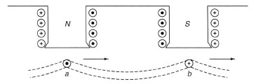
Figure 7.1 Conductor Current in a Synchronous Motor
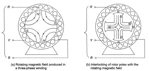
Figure 7.2 Rotating Magnetic Field and Rotor Field Poles Interlocking with Each Other
7.2 ARMATURE REACTION IN SYNCHRONOUS MOTORS
The effect of armature reaction for a leading current is shown in Figure 7.3 where the armature coil has been depicted as moving with the armature from left to right. When the coil axis is in position Y, shown by a dotted line, the coil sides are under the centres of the poles and the induced emf is maximum.
The induced emf will also be maximum at the instant when the terminal voltage is substantially 180° from it. Its direction is indicated in the dotted coil. If the current leads this terminal voltage by 90°, it will reach its maximum value one-fourth cycle ahead of the voltage, or at a time when the axis of the coils is in position X. For this position of the coil axis, the ampere-turns of the coil act in a direct opposite to those of the north pole. Therefore, the effect of armature reaction due to the leading current in the synchronous motor weakens the field.
Similarly, the effect of armature reaction due to lagging current strengthens the field and a unity power factor current cross-magnetizes the main field. The effect of armature reaction in synchronous motors is just the opposite to the effect in a synchronous generator or an alternator.
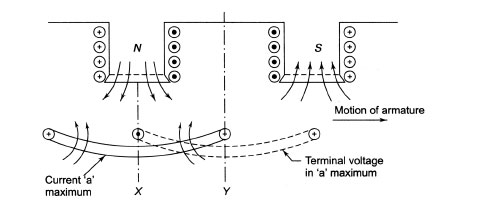
Figure 7.3 Demagnetizing Effect of Leading Current on the Field of Synchronous Motors
7.3 PHASOR DIAGRAM OF SYNCHRONOUS MOTOR
Due to different natures of the load, that is, lagging, leading and unity power factor of the load, three different phasor diagrams of a synchronous motor are obtained.
7.3.1 Effect of Loading Synchronous Motor
Figure 7.4 shows the circuit model of a synchronous motor having cylindrical rotor. In Figure 7.4
![]() is the applied voltage per phase,
is the applied voltage per phase,
![]() is the excitation voltage per phase,
is the excitation voltage per phase,
![]() is the armature current per phase,
is the armature current per phase,
![]() is the armature resistance per phase, and
is the armature resistance per phase, and
Xs is the synchronous reactance per phase.
The emf Ef is similar to the back emf of a DC motor. The voltage equation of a synchronous motor is given by
7.3.2 Lagging Power Factor Load
The phasor diagram of a synchronous motor under lagging power factor load is shown in Figure 7.5, where Ia lags behind Vt by an angle β.
In Figure 7.5,
![]()
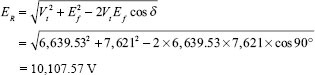
ER = IaZs is the voltage drop across synchronous impedance per phase, and Ia lags behind ER by an angle θ.
Let Vt be the phase voltage applied and Ef be the back emf induced per phase.
The angle between Vt and ER is θ – β.
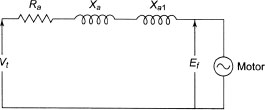
Figure 7.4 Equivalent Circuit Model of a Synchronous Motor
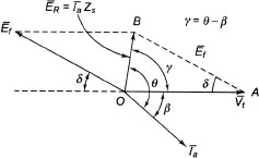
Figure 7.5 Phasor Diagram at Lagging Power Factor Load
From Figure 7.5, using cosine rule in ΔOAB, we have
![]()
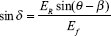
Using sine rule in ΔOAB, we have
Ef has already been calculated. Therefore, sin δ can be calculated using Equation (7.3).
7.3.3 Leading Power Factor Load
The phasor diagram of a synchronous motor under leading power factor load is shown in Figure 7.6,
where Ia leads Vt by an angle β.
In Figure 7.6, Ia lags behind ER by an angle θ.
Let Vt be the phase voltage applied and Ef be the back emf induced per phase.
The angle between Vt and ER is θ + β.
From Figure 7.6, using cosine rule in ΔOAB, we have
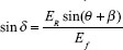
Using sine rule in ΔOAB, we have
![]()
![]()
Ef has already been calculated. Therefore, sin δ can be calculated using Eq(7.5).
7.3.4 Unity Power Factor Load
The phasor diagram of a synchronous motor for unity power factor load is shown in Figure 7.7, where Ia is in phase with Vt.
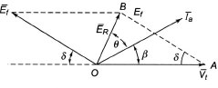
Figure 7.6 Phasor Diagram at Leading Power Factor Load
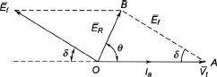
Figure 7.7 Phasor Diagram at Unity Power Factor
In Figure 7.7,
ER = IaZs is the voltage drop across synchronous impedance per phase.
Let Vt be the phase voltage applied and Ef be the back emf induced per phase.
The angle between Vt and ER is θ.
From Figure 7.7, using cosine rule in ΔOAB, we have
![]()
Using sine rule in ΔOAB, we have
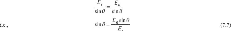
Ef has already been calculated. Therefore, sin δ can be calculated using Equation (7.7).
With an increase in load, the phase difference between the applied voltage Vt and the excitation Ef increases. As the angle δ increases with increasing load on the synchronous motor, it is called the load angle. The angle δ is also known as the power angle, coupling angle, torque angle or angle of retardation.
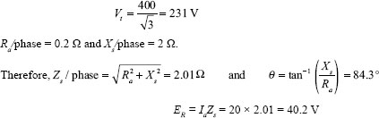
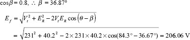
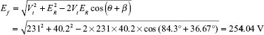
Example 7.1 A three-phase, 400 V, star-connected synchronous motor has an effective armature resistance and a synchronous reactance per phase of 0.2 Ω and 2 Ω, respectively. It takes 20 A to drive a certain load. Calculate the excitation emf induced in the motor if it works with (i)0.8 power factor lag,(ii)0.8 power factor lead and(iii)unity power factor conditions.
Solution
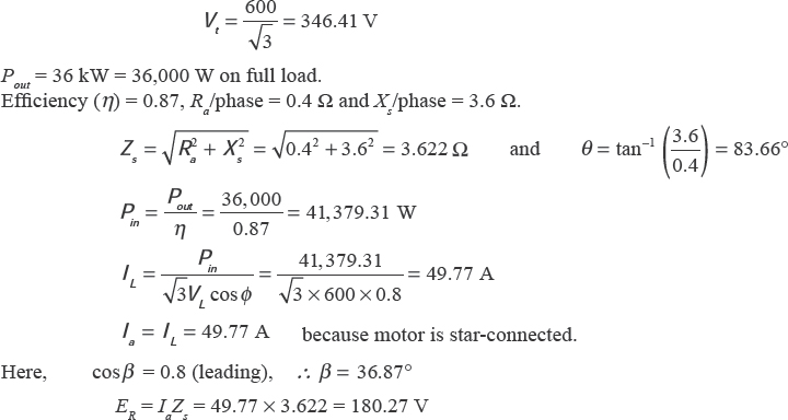
Example 7.2 A three-phase, 600 V, star-connected synchronous motor has an effective armature resistance and a synchronous reactance per phase of 0.4 Ω and 3.6 Ω, respectively. Calculate the induced emf per phase if the motor works on full load delivering 36 kW. The full-load efficiency is 87 per cent having a power factor of 0.8 leading. Also calculate the load angle.
Solution
For leading power factor, we have
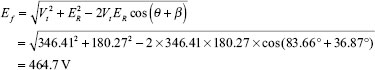
The generated emf per phase is 464.7 V.
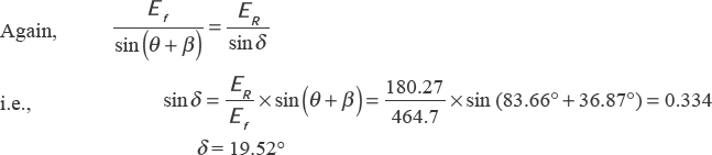
The load angle is 19.52°.
7.4 OPERATION AT A CONSTANT LOAD WITH VARIABLE EXCITATION
The phasor diagram of a synchronous motor at lagging power factor, unity power factor and leading power factor has already been shown. If the excitation is kept constant, the load current changes with the variation of load. In contrast, if the load is kept constant and the field excitation is varied, the synchronous motor reacts by changing its power factor of operation, which is the most interesting feature of the synchronous motor. Let us consider a synchronous motor operating under a constant load having the corresponding load angle δ.
Let the field excitation be adjusted so that Ef = Vt This excitation is called normal excitation of the motor. The motor is drawing current Ia from the supply and the power input is Pin. The power factor of the motor is lagging in nature, as shown in Figure 7.8(a). With change in excitation there is hardly any change in losses. Therefore, power input remains the same for constant load demanding the same power output.
The input power(Pin) is expressed by
![]()
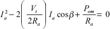
The applied voltage of the motor remains constant most of the time. Thus, for constant output, Ia cosβ will remain constant whatever be the value of cos β. Therefore, the motor adjusts the value of cosβ, to keep Ia cosβ constant. During variable excitation, the synchronous motor reacts by changing its power factor to give a constant output power.
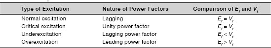
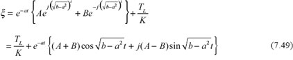
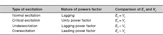
Figures 7.8 (b), 7.8(c) and 7.8 (d) show cases for underexcitation (Ef < Vt), overexcitation (Ef > Vt), and critical excitation ( Ef= Vt), respectively. From Figure 7.8, it is clear that Ia varies when excitation is varied from a low to a high value. For critical excitation, the current drawn by the motor is minimum compared to other excitations. Table 7.1 shows the details.
Table 7.1 Comparison of Various Excitations
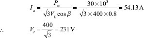
Example 7.3 A three-phase, 400 V, star-connected synchronous motor drives a constant load and draws a line current of 30 A, having an effective armature resistance and a synchronous reactance per phase of 0.2 Ω and 2 Ω, respectively. Find the power factor at which the motor will operate when the field current is adjusted to give the line values of generated emf from (i) 500 V to (ii) 300 V.
Solution
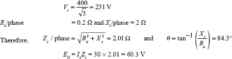
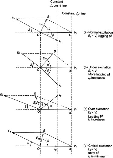
Figure 7.8 Operation of Synchronous Motor at Variable Excitation
- (i) Induced emf(line value) = 500 V
Induced emf per phase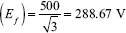
SinceEf > Vt, the motor operates at leading power factor. Let Ia lead V t by an angleβ
Now,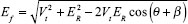
i.e.,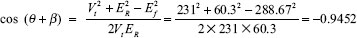
i.e.,
i.e.,
i.e.,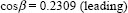
The required power factor is 0.2309 (leading) - (ii) Induced emf (line value) = 300 V
Induced emf per phase (Ef)
Since Ef < Vt, the motor operates at lagging power factor. Let Ia lag Vt by an angle β.
Now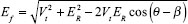
i.e.,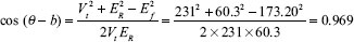
i.e.,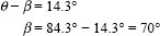
i.e.,
The required power factor is 0.342 (lagging)?
Example 7.4 A 8kW, 500 V, three-phase, star-connected synchronous motor has negligible armature resistance. The synchronous reactance/phase is 12 Ω. Calculate the minimum current that the motor will draw if excitation is varied. Find the corresponding induced emf/phase. The full-load efficiency of the motor is 86 per cent.
Solution
At unity power factor, armature current becomes minimum.
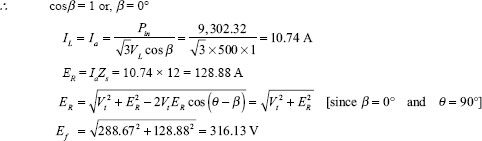
The corresponding induced emf is 316.13 V. ?
7.5 V CURVES AND INVERTED V CURVES
From Figure 7.8, we have concluded that there is variation of Ia with change of excitation. Ia becomes minimum for unity power factor as depicted in Figure 7.9. Excitation of the field can be changed by changing the rheostat in the field circuit.
The plot of armature current (Ia) with the field current ( If) takes the shape of English alphabet V. That is why the family of curves for various loads are called V curves, shown in Figure 7.10(a). In contrast, if the power factor (cosβ) is plotted against the field current, the graph looks like an inverted V. The family of curves obtained by plotting power factor against field current for various load conditions is known as inverted V curves of synchronous motor, shown in Figure 7.10(b)
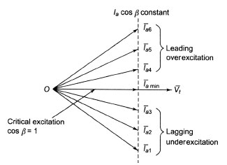
Figure 7.9 Variation of Armature Current with Field Excitation
Figure 7.11 shows the experimental set-up to obtain V curves. A three-phase supply is given to stator, as shown in Figure 7.11. The two-wattmeter method is used to measure the input power. Ammeter reading gives the line current, whereas voltmeter reading gives the line voltage. A rheostat is used in the field circuit to adjust the excitation to operate the motor under variable excitation.
7.6 COMPLEX POWER INPUT OF SYNCHRONOUS MOTOR
The phasor diagram of a synchronous motor at lagging power factor is shown in Figure 7.5, whereas Figure 7.4 shows its circuit diagram. At lagging power factor, Ef lags the applied voltage by an angle δ. Let us take Vt as the reference phasor.
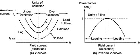
Figure 7.10 V and Inverted V Curves
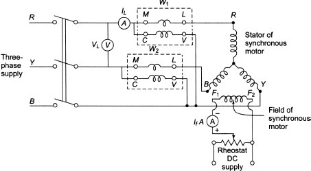
Figure 7.11 Experimental Set-up for V Curves
![]()
From, Figure 7.4
The complex input power per phase to the synchronous motor is given by
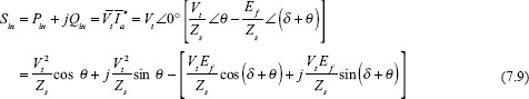
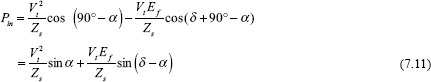
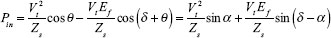
Equating real parts on both the sides of Equation(7.9), we have
Again, θ = 90° – α
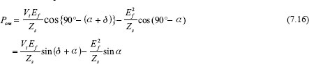
Therefore, the expression for real power becomes
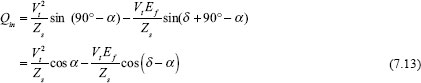
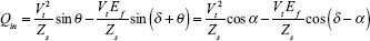
Equating imaginary parts on both the sides of Equation(7.9), we have

Therefore, the expression for reactive power becomes
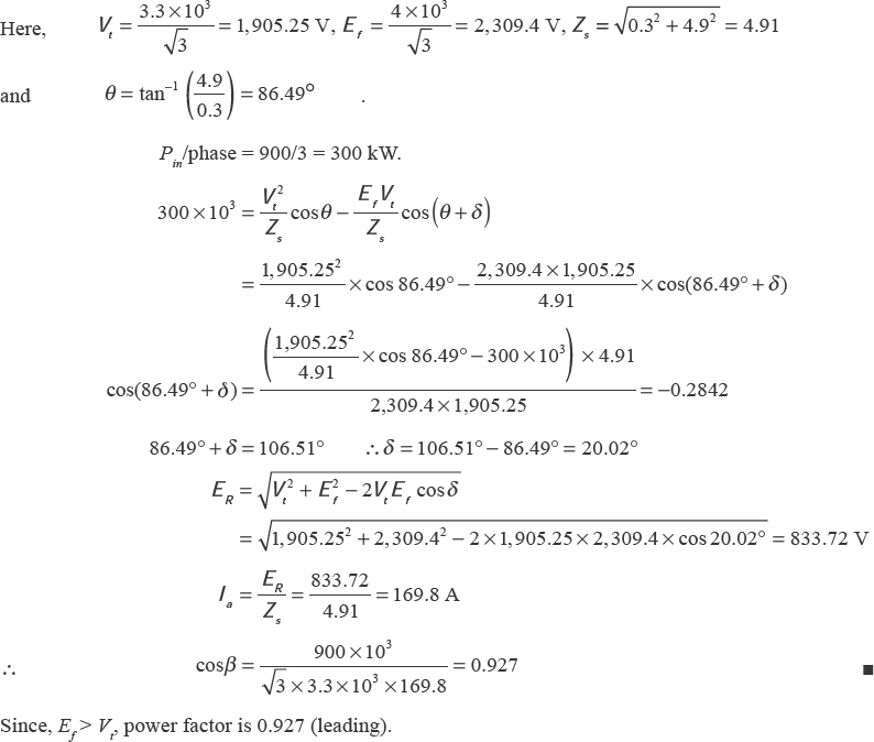
Example 7.5 A three-phase, 3.3 kV, 50 Hz, star-connected synchronous motor has a synchronous impedance of (0.3 + j4.9) Ω/phase. Calculate the line current and the power factor for an induced emf of 4 kV and an input power of 900 kW at rated voltage.
Solution
7.7 COMPLEX POWER OUTPUT OF A SYNCHRONOUS MOTOR
The complex output power per phase to the synchronous motor is given by
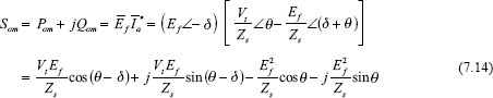
Equating real parts on both the sides of Equation(7.14), we have
Again, θ = 90° – α
Therefore, the expression for real power becomes
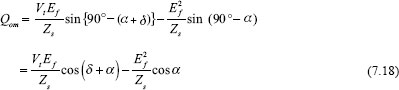
Equating imaginary parts on both the sides of Equation(7.14), we have

Again, θ = 90° – α
Therefore, the expression for reactive power becomes
The shaft power (or the net output power) Psh = Pom– rotational losses
Pom is called the mechanical power or the gross power developed. Rotational losses include friction, windage and core losses.
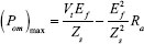
7.8 MAXIMUM OUTPUT POWER
For maximum output power, the following relations must hold good:
![]()
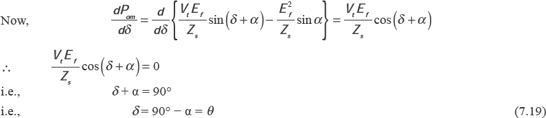
Therefore, maximum power output occurs at δ = θ, which is the limit of steady-state stability. The maximum output power of the motor is given by
Example 7.6 A 50 Hz, four-pole, three-phase, star-connected synchronous motor has a synchronous reactance of 12 Ω/phase and negligible armature resistance. The excitation is such as to give an open-circuit voltage of 13.2 kV. The motor is connected to a 11.5 kV, 50 Hz supply. What maximum load can the motor supply before losing synchronism? What is the corresponding motor torque, line current and power factor?
Solution
Supply voltage per phase ![]()
Induced emf/phase![]()
Since armature resistance is negligible, impedance angle is θ = 90°.
For development of maximum power, δ = θ = 90°
Impedance drop
Since motor is star connected, line current = phase current.
![]()
The maximum load delivered by the motor is as follows:
![]()
Since armature resistance is negligible, power input to motor = 12.65 MW
![]()
Developed torque corresponding to the maximum power is as follows:
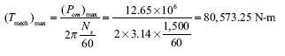
7.9 POWER OUTPUT WHEN ARMATURE RESISTANCE IS NEGLIGIBLE
Neglecting armature resistance, Equation(7.15) can be expressed as follows:
where ![]() is the maximum power developed by the motor.
is the maximum power developed by the motor.
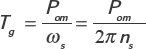
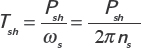
Gross torque developed by the motor is as follows:
where ns is the synchronous speed of the motor in rps.
Shaft torque of the motor is given by
where Psh = Pom - windage and friction losses
7.10 INPUT REACTIVE POWER WHEN ARMATURE RESISTANCE IS NEGLIGIBLE
- (i) If |Ef|cosδ>|Vt|, motor is overexcited. It delivers reactive power to the infinite bus. Under thiscondition motor is operating at leading power factor.
- (ii) If |Ef|cosδ=| Vt|, motor is normally excited. It neither delivers to nor absorbs reactive power
from the infinite bus. Under this condition motor is operating at unity power factor. - (iii) If | Ef|cosδ<| Vt|, motor is underexcited. It absorbs reactive power from the infinite bus. Under this condition motor is operating at lagging power factor.
7.11 MOTOR CHARACTERISTICS, PERFORMANCE AND CIRCLE DIAGRAM OF A SYNCHRONOUS MOTOR
The study of characteristics, performance and circle diagram of a synchronous motor is of utmost importance. These are discussed below.
7.11.1 Current Locus for Constant Power Input
The current locus for constant power input (Pin) is shown in Figure 7.12.
For a given power input (Pin) of the synchronous motor, the input power per phase ![]()
If Vt be the applied voltage/phase, the power component of the current is as follows:
A vertical line is at first erected, representing the axis for the voltage Vt. A horizontal line is drawn at a point P such that OP = Pin/3Vt. The current locus varies on the straight line for various powers. For less excitation, it takes a lagging current (the current vector lying on the right side of the voltage vector Vt), whereas it takes a leading current (the current vector lying on the left side of voltage vector Vt) for overexcitation. Similarly, the current locus is another horizontal line drawn at a distance of Ia cosβ from the origin, corresponding to the new value of input power Pin.
7.11.2 Current Locus for Constant Power Developed (Pom)
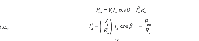
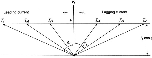
Figure 7.12 Current Locus for Constant Power Input

In Figure 7.13, ![]() and Ia are taken as two sides of a triangle, shown by OC and OK, respectively. The third side is
and Ia are taken as two sides of a triangle, shown by OC and OK, respectively. The third side is 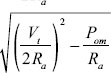 When Pom remains constant, both
 ![]() and
and  are constant. The locus of the current phasor Ia (shown by OK in Figure 7.13), as β changes, is a circle. The radius of the circle is
 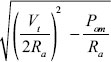 and the coordinate of the centre is
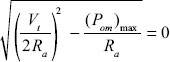
From the current locus, it is possible to infer that the power developed increases, the radius CK goes on decreasing, and hence the current locus becomes a circle of smaller diameter. For the development of maximu Pom, the radius of the circle must be zero.
![]()
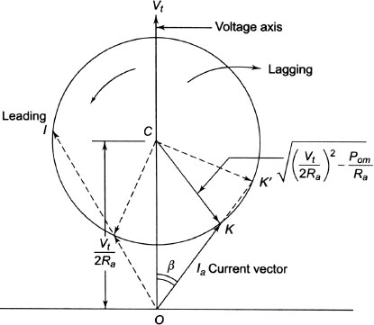
Figure 7.13 Current Locus for Constant Power Developed (Pom)
When the mechanical power developed is maximum, the current vector ![]() lies on the voltage vector
lies on the voltage vector![]() having a magnitude of
having a magnitude of ![]()
Hence, the power input/phase ![]()
The armature Cu loss/phase 
Power developed Pom = Pi–armature copper loss ![]()
The above equation checks with Equation (7.28). The efficiency at maximum output becomes 50 per cent. Losses become half of the input and rise of temperature would be above the maximum permissible temperature limit. Therefore, ![]() is not possible to achieve in practice.
is not possible to achieve in practice.
The dotted lines, which are to the left of the voltage vector Vt, show the details for a leading current. Rearranging Equation (7.27), we have

Armature current has two values. One gives stable operating conditions, whereas the other gives unstable operating conditions.
7.11.3 Current Locus for Constant Excitation (Ef)
The sides of the triangle 1 shown in Figure 7.14 represent the voltage vector Vt impedance drop IaZs and the induced emf Ef. If all the three sides of this triangle are divided by Zs, we get triangle 2 with sides ![]() , Ia and
, Ia and ![]() shown on the right side of the vector Vt in Figure 7.14, which is nothing but triangle 1, with the magnitude reduced by Zs times and rotated back by an angle of θ. If the excitation remains constant,
shown on the right side of the vector Vt in Figure 7.14, which is nothing but triangle 1, with the magnitude reduced by Zs times and rotated back by an angle of θ. If the excitation remains constant, ![]() and
and ![]() remain constant and the current locus (Ia) is a circle drawn for a radius Ef/Zs from the point P. From Figure 7.14, we have
remain constant and the current locus (Ia) is a circle drawn for a radius Ef/Zs from the point P. From Figure 7.14, we have
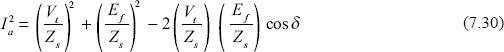
Therefore, Ia has two values. One value gives stable operation, whereas the other one corresponds to unstable operating conditions. The unstable operating point is represented by current Ia in Figure 7.14 and the angle δ between Ef/Zs and Vt/Zs for the unstable point is more than β, whereas the maximum value for angle δ for stable operation is the impedance angle β
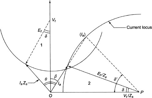
Figure 7.14 Current Locus for Constant Excitation
When the synchronous motor is loaded, the rotor falls back from the stator rotating magnetic field by an angle δ and continues to rotate at synchronous speed. If the load further increases, the angle δ also increases. The motor becomes unstable and it may not be able to rotate along with the rotating field if δ goes beyond β
7.12 TORQUE OF A SYNCHRONOUS MOTOR
- Starting torque: The ability of the motor to accelerate the load is called the starting torque. Sometimes it is also called the breakaway torque.
In centrifugal pumps it is 10 per cent of the full-load torque, whereas in reciprocating pumps it is 200 to 250 per cent of the full-load torque.
- Running torque: The motor under running condition develops this torque which is determined by the output power and the speed of the driven machine.
- Pull torque: The ability of the motor to pull into synchronism during change from induction to synchronous motor operation is called the pull torque.
- Pull-out torque: It is the maximum torque that the motor will develop without pulling out of synchronism. Its value varies from 1.25 to 3.5 times the full-load torque.
7.13 SALIENT-POLE SYNCHRONOUS MOTOR –TWO-REACTION MODEL
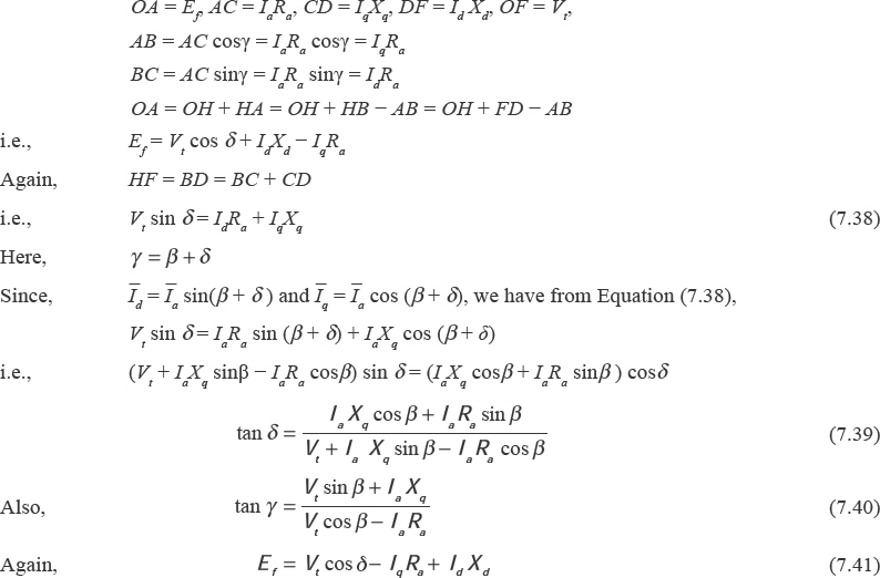
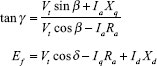
Salient-pole synchronous generator has already been discussed in Chapter 6. Let us study the phasor diagram of the salient-pole synchronous motor. The voltage equation of synchronous motor is expressed by
![]()
where Xd and Xq are the direct and quadrature axis reactance of the armature.
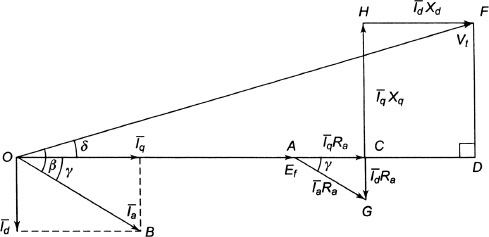
Figure 7.15 Lagging Power Factor
7.13.1 Lagging Power Factor
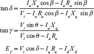
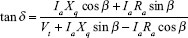
The phasor diagram for a synchronous motor for lagging power factor is shown in Figure 7.15. In Figure 7.15,
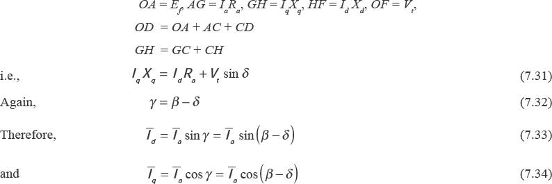
From equations (7.31), (7.33) and (7.34), we have

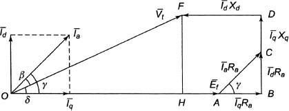
Figure 7.16 Leading Power Factor
7.13.2 Leading Power Factor
The phasor diagram for a synchronous motor for leading power factor is shown in Figure 7.16.
In Figure 7.16,
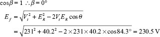
7.13.3 Unity Power Factor
For unity power factor, cosβ=1 and sinβ= 0.
Figure 7.17 shows the phasor diagram of the synchronous motor at unity power factor.
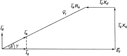
Figure 7.17 Unity Power Factor
If the resistance of the armature is of negligible order, the phasor diagrams of the synchronous motor at lagging, leading and unity power factor are shown in Figures 7.18, 7.19 and 7.20, respectively.
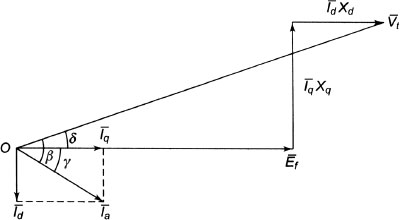
Figure 7.18 Lagging Power Factor
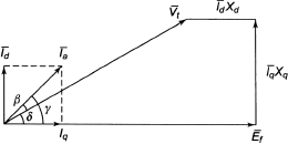
Figure 7.19 Leading Power Factor
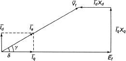
Figure 7.20 Unity Power Factor
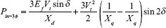
7.14 POWER DEVELOPED BY A SALIENT-POLE SYNCHRONOUS MOTOR
The input power is the sum of the product of the in-phase components of the current and voltage and the product of quadrature components.
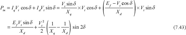
Therefore, the total power input is given by

The power developed is equal to the total power input minus the losses.
7.14.1 Stability and Maximum Load Angle
Differentiating Equation(7.43) with respect to load angle, we have
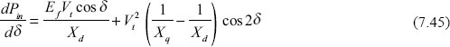
Equation(7.45) represents the rate of change of Pin with respect to δ. This is termed as the stability factor, rigidity factor or the stiffness of coupling.
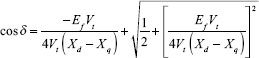
To obtain the maximum value of Pin
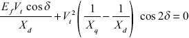
i.e., 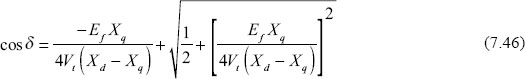
Equation(7.46) shows the requiredvalue of cos δ to get maximum power input.
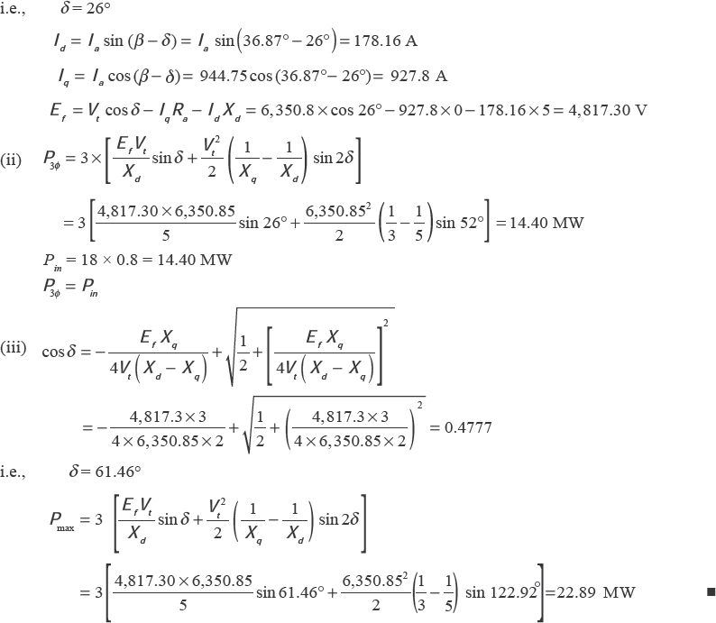
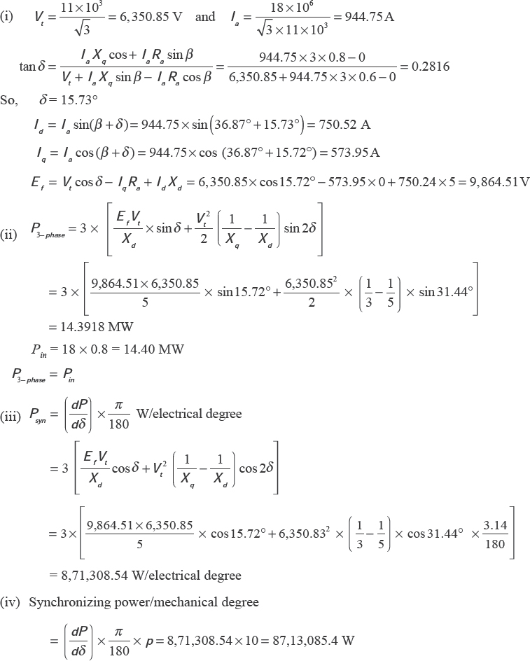
Example 7.7 A three-phase, 18 MVA, 10 pole, 50 Hz, 11 kV, star-connected synchronous motor has Xd = 5 Ω, and Xq = 3 Ω respectively. It has negligible armature resistance. Calculate the following on full load at0.8 power factor lagging:
- (i) The excitation voltage.
- (ii) The power.
- (iii) The maximum value of power angle and the corresponding power.
Solution

7.15 DAMPER WINDINGS
Damper windings are provided in different machines such as alternators and induction-start synchronous motors.
The addition of copper damper windings to machines effectively simplifies the characteristics of the machines by largely eliminating the harmonics. Damper windings are of the following types:
- (i) Connected damper winding: This type of winding is similar to squirrel cage of an induction motor, which is continuous between the poles for a slow-speed machine, whereas additional end rings are brazed to the copper rods for higher-speed machines. In this type of dampers, Xq ≍ Xd.
- (ii) Non-connected damper winding: This type of winding in each pole face is independent from those in the adjacent poles, and Xq ≠ Xd.
- (iii) Special damper winding: Dampers with this type of winding use double windings, one of which has high resistance and low reactance and the has low resistance and high reactance. This type of damper winding is used in motors to provide better starting characteristics. At low speeds, the high reactance of the low-resistance windings forces the current to flow through the high resistance winding, which produces a high torque. At higher speeds, the low-resistance winding becomes effective.
7.16 DAMPING EFFECT
Adding damper windings in generators provides a low-resistance path for the flow of current. It also prevents both wave distortion and excessive heating. The best criteria of a polyphase machine to carry unbalanced load are its negative sequence reactance and resistance. The former reflects its ability to prevent unbalancing of the voltage and the latter, its ability to carry the negative sequence current without undue heating of the rotor. These properties are particularly important for such fluctuating loads as electric furnaces. Not only do the dampers reduce the voltage unbalance but they also reduce waveform distortion.
Synchronous generator feeds load through transmission lines having a low ratio of resistance to reactance, and it tends to set up spontaneous hunting that is greater at light loads than at heavy loads.
The rotor oscillates during a system disturbance. The damper bars have a relative movement with respect to the air-gap flux that causes induction of the emf and the flow of current in these bars/windings. The bar current creates the emf according to Lenz's law, which always opposes the relative motion. Therefore, a positive damping term comes to play to reduce the amplitude of the oscillatory motions of the rotor about the operating point. The rotor Ωuickly returns to the steady position. These short-circuited bars are known as ‘damper winding or amortisseur winding'. These act like the squirrel cage of an induction motor and provide a starting torque for the motor which otherwise, being of synchronous kind, is non self-starting. Therefore, the damper windings serve a dual purpose. During start-up, synchronous motor achieves a speed close to synchronous. The rotor and stator fields lock with each other as soon as the field excitation is switched on. The damper bars in synchronous machines prevent hunting of the machine.
7.17 HUNTING/SURGING OF SYNCHRONOUS MOTORS
During operation within the region of stability with a fixed excitation operating, an increase in load results in a change in the rotor position from its original value or, the rotor slips backwards relative to the armature field through an angle of Δδ in electrical degrees. An instantaneous adjustment to the changed load conditions is not possible due to the inertia of the rotor and its connected load. Therefore, the rotor swings back somewhat beyond the position of equilibrium and develops torque in excess of the load requirements. This not only checks the initial reduction of speed but also increases the speed slightly above the synchronous speed and there is a periodic swinging of rotor set-up first to one side, then to the other of the new position of equilibrium. This oscillation is superimposed on the uniform synchronous speed of rotation.
Figure 7.21 shows the oscillation of rotor with respect to time. The synchronous motor is operating with a load angle δ before the application of a sudden load. Immediately after the application of load, the new load demands an increase of angle δ1 to a value δ2, but the rotor will settle down at δ2 only after a few oscillations.
The relative to-and-fro motions of the rotor field with respect to the armature field results in production of eddy currents in the pole faces, which are always directed to oppose their cause as per Lenz's law, and hence tend to damp out these oscillations. Changes in δ are accompanied by changes in the armature current. To suppress the objectionable hunting more effectively than by eddy currents in the pole faces, synchronous motors are always provided with damper windings. These windings in the rotor are short-circuited. There is a current produced in the winding due to rotor swing with respect to synchronous speed, which results in a torque opposing the change in speed.
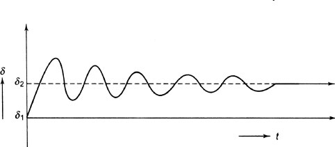
Figure 7.21 Oscillation of Rotor with Respect to Time
7.18 PERIODICITY OF HUNTING
After sudden application of an additional load equivalent to a torque TL, the rotor will be displaced from its initial ξ electrical degrees, which is equivalent to an actual space of ![]() , where P is the number of poles at any given time t. If J is the polar moment of inertia including its connected load, the accelerat ing torque is
, where P is the number of poles at any given time t. If J is the polar moment of inertia including its connected load, the accelerat ing torque is![]()
The externally applied torque TL must be equalto the sum of internally developed torques. In spite of the initialtorque torques due to the elastic pull of the magnetic field upon the field poles and the frictional or braking torque due to the currents in the damping winding come into action.
Inertial torque ![]()
Torque due to the elastic pull of magnetic field = K1δPom and frictional or braking torque 
The complete equationof motion may be expressed as
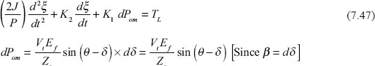
Substituting for δPom in Equation(7.47), we have
![]()
which may be written as
The Solution for Equation (7.48) is given by
![]()
Three possibilities occur, defined by the condition.
- (i) a2>b → overdamped
- (ii) a2 = b → critically damped
- (iii) a2 < b → underdamped
When a2 < b, it leads to imaginary exponents
At t = 0, ξ = 0 and ![]()
Hence. ![]()
Substituting the values of A + B and y(A – B) from Equations (7.50) and (7.51) in equation(7.40), we have
Therefore,ξ approaches its ultimate or steady-state value ![]() by a transient series of oscillations of decreasing amplitude and the frequency of the oscillation is
by a transient series of oscillations of decreasing amplitude and the frequency of the oscillation is
The period of oscillation is given by ![]()
7.19 METHODS OF STARTING OF SYNCHRONOUS MOTORS
Since synchronous motors are not self-starting inherently, we should have some means for starting synchronous motors. The methods are discussed here.
- (i) Induction motor start: Damper windings consisting of copper bronze bars embedded in slots in the pole faces and short-circuited at both ends are usually provided in synchronous motors, which serve not only to damp out oscillations during hunting but are also suitably designed as a sequirrel-cage winding for starting purposes. If the rotor reaches near synchronous speed, the field circuit is suddenly energized and the rotor and the stator fields interlock each other. The voltage induced in the field winding at standstill may reach very high values, which is dangerous to life and to the insulation. The field winding is sometimes interrupted at several points by some form to field breaking switch to limit this voltage to a safe value. A better way to limit the induced voltage in the field windings is to reduce the voltage impressed upon the armature terminals to a fraction of normal voltage (30 to 50 percent) using an auto-transformer.
- (ii) Auxiliary motor start: Using an auxiliary motor, the synchronous motor is first run as an alternator and is synchronized with the three-phase bus bars. After synchronization, supply to auxiliary motor is cut and the alternator is made to run as a synchronous motor drawing power from three-phase AC mains.
- (iii) Using resistor in the field circuit: Instead of leaving the field circuit open during the starting stage of a synchronous motor, it can be short-circuited and can be used as a damper winding. When an additional resistance of a value 100 times that of the field resistance is inserted in series with the field the starting torque will be large. The field resistance is reduced as the motor accelerates until it becomes three to four times that of the field itself. This method can be used in machines in which large starting torques are required.
- (iv) Phase connected damper windings: When the starting torque required wis of the order of 200 percent of the full-loadtorque as in the case of tube mills for making cement, machines have been built that employ the principle of the slip ring induction motor. The bars of damper windings embedded in the pole faces are connected to form a balanced three-phase winding, with the terminals connected through slip rings to an adjustable rheostat. The starting resistance is then cut out in successive steps, until the windings are completely short-circuited.
- (v) Super synchronous start: The armature is not rigidly bolted to the bedplates as in an ordinary motor. It is capable of rotating about the rotor shaft. But under normal conditions, it is held stationary by a brake band surrounding the frame of the armature core. The rotor is mechanically coupled to load. The brake band on stator is released, and when line voltage is impressed on armature terminals, the stator will try to rotate. When the armature reaches near synchronous speed, the rotor field isexcited and the machine pulls into synchronism. Thereafter, the brake band on armature is graduallytightened and as the armature slows down, the rotor tries to pick up speed. When armature is held stationary, the rotor attains synchronous speed. This is a misnomer.
7.20 APPLICATIONS OF SYNCHRONOUS MOTOR
Synchronous motors are hardly used below 50 HP in the medium range due to their higher initial cost compared to induction motors. ADC excitation source is requiredand the starting and control devices are usually more expensive, especially in which automatic operation is required. However, there are certain advantages offered by synchronous motors:
- (i) Constant speed operation.
- (ii) Power factor control.
- (iii) High operating efficiency.
Table 7.2 shows some important characteristics of the synchronous motor along with some applications.
Table 7.2 Synchronous Motor Characteristics and Applications
7.21 SYNCHRONOUS CONDENSERS
Synchronous condensers are synchronous motors used for power factor correction alone without any mechanical output. It draws leading current, as a static condenser does, which is useful for installations of low power factor. The synchronous motors when overexcited act like capacitors. To take leading kVA, it can be connected to a system to improve its power factor. The synchronous condenser is specially designed so that practically all its rated kVA are available for power factor correction. Because of this feature, they are applied particularly to transmission line control.
At load (losses assumed negligible), a synchronous motor operates at a δ = 0, which means that Efand Vt are in phase ( Ef = excitation emf and V t = voltage at the motor terminals)
When the motor draws zero power factor leading current is shown in Figure 7.22(a).
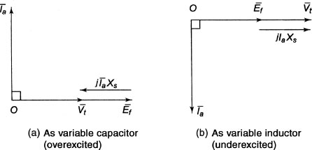
Figure 7.22 Synchronous Condenser
When the motor draws zero power factor lagging current is shown in Figure 7.22(b)
ADDITIONAL SOLVED PROBLEMS
Example 7.8 A three-phase, star-connected, 6,600 V synchronous motor has a synchronous reactance per phase of 15Ω. For a certain load, the input is 900 kW at normal voltage and the induced line emf is 8,900 V Neglecting armature resistance, determine the following:
- (i) Line current.
- (ii) Power factor.
Solution
Synchronous reactance/phase Xs = 15Ω
Input to motor = 900 kW
Supply phase voltage ![]()
Induced emf/phase Ef ![]()
Resistance Ra = 0
Since the induced emf is greater than the supply voltage, the motor will operate at leading power factor. Armature current ( Ia) = line current ( IL) because the motor is star connected.
Since power input =![]()

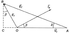
From right-angled ΔABC (Figure E7.1), we have
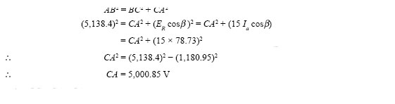
But OC = CA – OA = 5,000.85 – 3,810.5 = 1,190.35 V
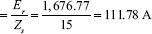
Now ![]()
- (i) Line current = phase current ( Ia)
- (ii) Power factor (cos β)
Example 7.9 A 6.6-kV star-connected, three-phase synchronous motor works at constant voltage and constant excitation. Its synchronous reactance is 18 Ω per phase; neglect resistance. When the input is 1,111.145 kW, the power factor is0.8 leading. Find the power factor when the input is changed to 1,500 kW.
Solution
Supply voltage per phase ![]()
Xs = 18Ω
Internal angle ![]()
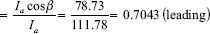
When the input is 1,111.145 kW at0.8 power factor leading:
Armature current/phase 
![]()
Here, 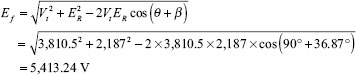
When power is changed to 1,500 W, the excitation (5,413.24 V per phase) and supply voltage (per phase) remain constant.
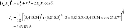
![]()
Power/Phase ![]()
Again, ![]()
i.e., ![]()
i.e., δ = 25.87°
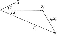
From phasor diagram (Figure E7.2) of synchronous motor (neglecting Ia Ra), we have
![]()
Example 7.10 A three-phase, 400 V, star-connected synchronous motor has full load efficiency of 95 per cent and it takes 24 A on full load at unity power factor. What will be the back emf generated and total mechanical power developed in kW on full load and 0.9 power factor leading? The impedances/ phase is (0.2 + 2;)Ω.
Solution
Efficiency of synchronous motor = 95%
Full-load current Ia = 24A
Power factor = 1
Impedance/phase = (0.2 + j2)
The current at 0.9 power factor ![]()
Power input at 0.9 power factor ![]()
Terminal voltage ( Vt ) per phase ![]()
![]()
θ = 84.3°
cosβ= 0.9
![]()
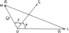
Refer to Figure E7.3
MOL = θ + β = 84.3° + 25.δ° = 110.1°
In ΔLOM, we have
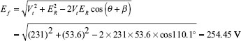
Induced line emf ![]()
In ΔLOM, ![]()
i.e., ![]()
i.e., ![]()
i.e., ![]()
Mechanical power developed = 3 x (emf induced per phase x armature current x cosine of the angle between the armature current and emf induced)
Let γ = angle between the armature current and the emf induced
=β + γ = 25.δ° + 11.4° = 37.2°
Mechanical power developed
![]()
Example 7.11 A 75 kW 400 V, four-pole, three-phase, star-connected synchronous motor has an effective armature resistance and a synchronous reactance per phase of 0.04 Ω and 0.4 Ω respectively. Compute the open-circuit emf phase and the gross mechanical power developed for full load at0.8 power factor leading. Assume an efficiency of 92.5 per cent.
Solution
Given: Motor output = 75 kW; VL = 400 V
Ra/phase = 0.04 Ω, Xs/phase = 0.4Ω, cosβ=0.8 (lead); η = 92.5%
Open-circuit emf Ef = 400 V
Phase voltage ![]()
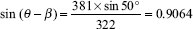
cosβ=0.8, β = cos-1 (0.δ) = 36.87° and sin/ = sin (36.87°) = 0.6.
Armature current ( Ia ) ![]()
Resultant voltage 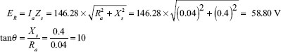
.: Internal angle θ = tan-1 (10) = 84.3°
For leading power factor, we have
Gross mechanical power developed for all the three phases is as follows:
![]()
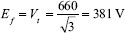
Example 7.12 A 20-pole, 30 kW, 660 V, 50 HZ, three-phase star-connected synchronous motor is operating with its generated voltage per phase exactly equalto the phase voltage applied to its armature. At loaded condition the motor is retarded by 5 mechanical degrees from its synchronous position. The synchronous reactance and the effective armature resistance are 10Ω and 1Ω per phase, respectively. Calculate the following:
- (i) The armature current per phase.
- (ii) The power phase and the total power drawn by the motor from the bus.
- (iii) The developed power.
Solution
Number of poles ( P) = 20; power output = 30 kW; VL = 660 V
Ra/phase = 1Ω and Xs/phase = 10Ω
- (i) Armature current/phase Ia
Induced emf per phase
Load angle
 angle of retardation in mechanical degrees
 electrical degrees
Impedance/phase
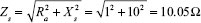
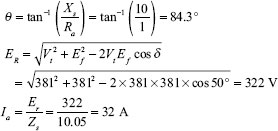
- (ii) Since Ef= Vt we have

i.e
i.e
i.e

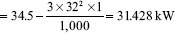
Power per phase = VtIa cosβ = 381 x 32 x cos19.3° = 11,507 W = 11.5 kW
Total power drawn = 3 x 11.5 = 34.5 kW
- (iii) Power developed:
Power developed = Total power drawn – 3 Ia2Ra
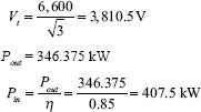
Example 7.13 A three-phase, 6.6 kV, star-connected synchronous motor delivers 346.375 kW at full load having full-load efficiency of 85 per cent. The effective armature resistance and the synchronous reactance per phase of the motor are 0.4 Ω and 4.2 Ω respectively. If the motor works at0.8 power factor lead on full load, calculate the following:
- (i) Generated emf on full load.
- (ii) Load angle.
Solution
![]()
Since the motor is star connected, Ia = IL = 77.18 A
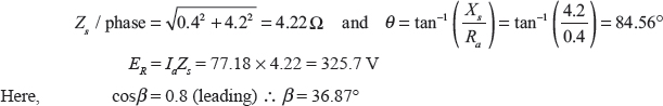
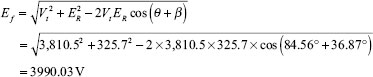
The generated emf per phase is 3,990.03 V.
Again, ![]()
i.e., ![]()
i.e., δ= 3.99°
Therefore, the load angle is 3.99°
Example 7.14 A 22 kW, 400 V, three-phase, star-connected synchronous motor has an effective armature resistance and a synchronous reactance per phase of 0Ω and 4 Ω respectively. The line value of the developed back emf is 520 V. Calculate the motor power factor and current drawn by the motor.
Solution
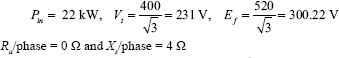
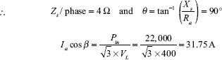
Since Ef > Vt, power factor is leading.
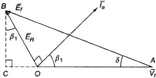
From phasor diagram (Figure E7.4), we have
BC = ER cosβ = Ia Zs cosβ and OC = ER sinβ = Ia Zs sinβ
From ΔCAB, we have,
AB2 = AC2 + BC2 = (OA + OC)2 + BC2
i.e., E2f = + IaZs sinP)2 + (IaZs cosp)2
i.e., 300.222 =(231 + 4Ia sinp) +(31.75 x 4)2
i.e ![]()
i.e., Ia sinβ = 41.03/4 = 10.26 A
![]()
β= 17.9°
cosβ = 0.951 (leading)
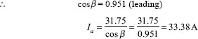
The current drawn by the motor is 33.38 A and the power factor is 0.951 (leading) ?
Example 7.15 A three-phase, 415 V, six-pole, 50 Hz star-connected synchronous motor has emf of 520 V (L-L). The stator winding has a synchronous reactance of 2Ω per phase and the motor develops a torque of 220 N-m. The motor is operating at 415 V, 50 Hz bus. Calculate the current drawn from the supply and its power factor. Assume Ra /phase = 0Ω
Solution
Per phase supply voltage ![]()
Induced emf per phase ![]()
Synchronous speed of the motor IN, ) ![]()
torque developed (T) = 220 N-m
Total power developed ![]()
Power developed per phase ![]()
Zs/phase = 2 Ω and θ = 90°
Power developed per phase is given by
![]()
Therefore, ![]()
Ω=0.2134°
Since Ef > Vt, we have
![]()
Current drawn per phase ![]()
Again, ![]()
i.e., ![]()
i.e., θ+β= 140.28°
β= 140.28°- θ= 140.28°-90°= 50.28°
Power factor = cos 50.28° = 0.6390 (leading)
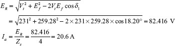
Example 7.16 A 500 V, three-phase, star-connected synchronous motor has a resistance and a synchronous reactance of 0.4 Ω and 3.6 Ω, respectively. The open-circuit voltage is 600 V If friction and core losses are 1 kW, calculate the line current and the power factor when the motor output is 62 kW.
Solution
Supply voltage per phase is ![]()
Induced emf per phase is ![]()
Here, Ef > Vt the power factor is leading.
Total mechanical power developed = 62 + 1 = 63 kW
Power developed per phase 
Power developed per phase is given by ![]()
i.e., ![]()
i.e., δ = 83.66° - 26.74° = 56.92°
We can write,
![]()
Since the motor is star connected, line current = phase current.
![]()
Again ![]()
i.e., ![]()
i.e., θ + β = 108.95°
i.e., β = 108.95° - 83.66° = 25.29°
.: Power factor = cos25.29° = 0.904 [leading]
Example 7.17 The excitation ofa415 V, three-phase, mesh-connected synchronous motor is such that the induced emf is 520 V. The impedance per phase is (0.5 + j4.0)Ω. If the friction and iron losses are constant at 1,000 W, calculate the power output, line current, power factor and efficiency for maximum power output.
Solution
Supply voltage per phase V t = 415 V, induced emf per phase Ef = 520 V
Synchronous impedance/phase ![]()
Impedance angle ![]()
Maximum power will be developed for the given motor, δ = θ = 82.9°
Here, Ef > Vt therefore, the power factor is leading.
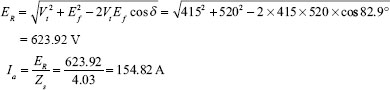
Line current(IL) ![]()
The maximum power developed by the motor is,
![]()
Output power = power developed - iron and friction losses = 1,35,765.38 - 1,000 = 1,34,765.38 W
Total Cu-loss = 3I2a Ra = 3 x 154.822 x 0.5 = 35953.85 W
Input power = power developed + Cu losses
= 1,34,765.38 + 35,953.85 = 1,70,719.23 W
Power factor (cosβ) ![]()
Efficiency ![]()
Example 7.18 A three-phase, 400 V, 40 kVA, 50 Hz, star-connected synchronous motor has a synchronous reactance of 4Ω Its friction and windage losses are 1.δ kW and core losses are 1.2 kW. The shaft load is 12 kW initially and the power factor of the motor is0.8 leading.
- (i) Calculate the line current, armature current and excitation emf.
- (ii) Calculate the new values of armature current and the motor power factor if the shaft load is increased to 22 kW. Excitation voltage is kept constant.
- (iii) Synchronizing power/electrical degree.
Solution
Since the motor is star connected, armature current = line current.
Armature current = 27.06 A
Here, Zs = 4 Ω and 6 = 90°
ER = 27.06 x 4 = 108.24 V
β = cos-1(0.8) = 36.87°
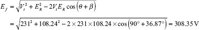
The line current, armature current and excitation voltage are 27.06 A, 27.06 A and 308.35 V, respectively.
(ii) Ef is kept constant and shaft load is interconnected to 22 kW.
Ef = 308.35 V
Since Ef > Vt, the power factor is leading in nature.
Therefore, the new armature current and power factor are 37.53 A and 0.961 (leading).
(iii) Psyn electrical degree 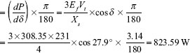
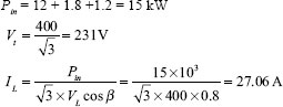
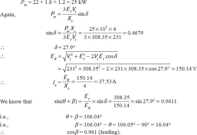
Example 7.19 A three-phase, 400 V, 40 kVA star-connected synchronous motor is supplying 15 kW load with0.8 power factor lagging. The windage and friction losses are 1.5 kW and the core losses are 1.0 kW. Calculate the following:
- (i) Armature current and excitation voltage.
- (ii) Armature current and power factor if the excitation is increased by 40 per cent and power supplied to the load remains constant.
Solution
(i)
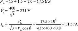
Since the motor is star connected, armature current = line current. Ia = 31.57 A.
Here, Z = 4 Ω and θ = 90°
ER = 31.57 x 4 = 126.28 V
β = cos-1(0.8) = 36.87°
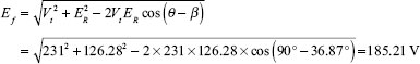
Again, ![]()
So, δ = 25.93°
(ii) Efl = 1.4 Ef = 1.4 x 185.2 = 259.28 V
Since the power supplied to the load remains constant, we have
Ef1 sin δ1 = Ef sin δ
i.e., ![]()
i.e., δ1 = 18.20°
Since Ef1 > Vt, power factor is leading.
Again, ![]()
i.e., ![]()
i.e., θ + β;1 = 100.7°
i.e., β;1 = 100.7° - 9 = 100. 7° - 90° = 10.7°
Therefore, power factor = cos β1 = cos 10.7° = 0.9826 (leading) ?
Example 7.20 A three-phase, 30 kW, 400 V, star-connected synchronous motor operates on full load at0.8 power factor lagging. The machine has a synchronous reactance of 4 ΩΩs and negligible armature resistance. Calculate the new value of current and the power factor if excitation is increased by 50 per cent.
Here, Zs = 4 Ω and θ = 90°
Since cosβ =0.8 (lagging), β = 36.87°

Since Ef1 > Vt power factor is leading.
Let the armature current be Ia1 and the power factor be cosβ1 (leading).
![]()
BC = ER cosβj and OC = ER sin#
Ef = CA2 + CB2 = (F, + Ia1Zs sinβ1 )2 + ( la1Zs cos β1 )2
i.e., 3 00.8252 =(231 + 4 Ial sinβ1 )2 +(4 x 43.30)2
i.e., ![]()
i.e., ![]()
i.e., ![]()
i.e., ![]()
i.e., 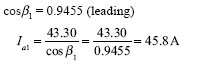
Therefore, the armature current and the power factor of the motor are 45.δ A and 0.9455 (leading) ?
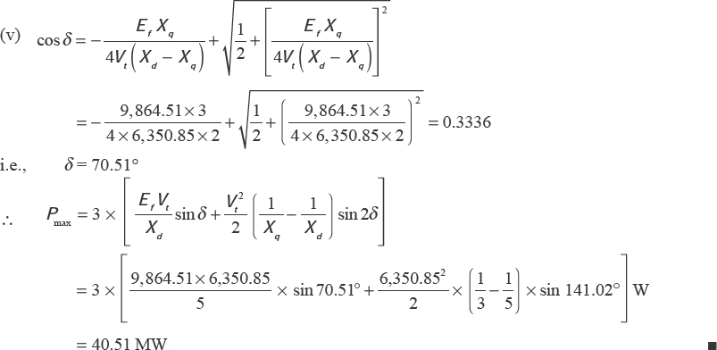
Example 7.21 A three-phase, 18 MVA, 10-pole, 50 Hz, 11 kV, star-connected synchronous motor has Xd = 5 Ω, and XΩ = 3 Ω, respectively. It has negligible armature resistance. Calculate the following on full load at0.8 power factor leading:
- (i) Excitation voltage.
- (ii) Power.
- (iii) Synchronizing power/electrical degree
- (iv) Synchronizing power/mechanical degree
- (v) Maximum value of power angle and the corresponding power
Solution
SIGNIFICANT POINTS
- For lagging power factor:
- For leading power factor:
- For unity power factor:

where pf = cosβ and δ is the power angle.
- Comparison of various excitations:
- Expression for real power:
- Expression for reactive power:
- Maximum output power:
- When armature resistance is negligible:

where
 is the maximum power developed by the motor.
Gross torque developed by the motor is,
where ns is the synchronous speed of the motor in rps.
Shaft torque of the motor is given by
where Psh = Pom –windage and friction losses
Various cases:
- (i) If Ef cosδ > |Vt|, motor is overexcited. It delivers reactive power to the infinite bus. Under this condition motor is operating at leading power factor.
- (ii) If Efcosδ = Vt, motor is normally excited. It neither delivers to nor absorbs reactive power from the infinite bus. Under this condition motor is operating at unity power factor.
- (iii) If Ef cosδ < Vt, motor is underexcited. It absorbs reactive power from the infinite bus. Underthis condition, motor is operating at lagging power factor.
- Salient-pole type:
For lagging power factor:
For leading power factor:

Power developed:
Condition for maximum power
SHORT QUESTIONS AND ANSWERS
Q.1 What is a synchronous motor and where is it used?
Ans. A synchronous motor is a machine in which a DC supply is given to the rotor and a three-phase AC power supply is given to the stator. It is used to improve the power factor of the line as well as for the load at constant speed.
Q.2 Why is it called synchronous motor?
Ans. Since the motor runs at synchronous speed in synchronism with the supply freΩuency, the motor is called synchronous motor.
Q.3 What is synchronous speed?
Ans. Yes, it runs at constant synchronous speed that is given by the equation ![]() rpm where f = supply frquency, P = number of poles and Ns = synchronous speed of the motor in rpm.
rpm where f = supply frquency, P = number of poles and Ns = synchronous speed of the motor in rpm.
Q.4 Can we vary the speed of a synchronous motor in running condition?
Ans. No.
Q.5 How can the speed of a synchronous motor be changed?
Ans. The speed of a synchronous motor can be changed by varying the freΩuency with special arrange-
ment.
Q.6 In which motor do the stator field and the rotor field rotate simultaneously?
Ans. Stator field and rotor field rotate simultaneously in a synchronous motor.
Q.7 In which motor is the air gap more than that of the other motors?
Ans. The air gap is more in salient-pole synchronous motor compared to other motors.
Q.δ From where is DC excitation given in the field of synchronous motor?
Ans. The DC excitation is provided by an exciter (DC generator) driven either by mounting on the same shaft or by a separate motor.
Q.9 What do you mean by exciter? How much voltage is induced by this exciter?
Ans. Exciter is a DC shunt or compound generator by which the voltage is induced upto 250 volts.
Q.10 Is the synchronous motor self-started?
Ans. No
Q.11 Why is it necessary to employ special starting equipment for starting a synchronous motor? Ans. Special starting equipment is necessary because starting torque of synchronous motor is practically zero.
Q.12 What are the methods of starting a synchronous motor?
Ans. Various methods of starting a synchronous motor are as follows:
(i) By means of a DC compound motor directly coupled or belted to the main motor.
(ii) By means of a pony motor (a small induction motor directly coupled or bolted to the
main motor).
(iii) The motor is made self-starting by providing damper winding on motor poles.
Q.13 How does a synchronous motor improve power factor?
Ans. By keeping load constant and running the motor overexcited, leading current is drawn from the supply mains thus improving the power factor.
Q.14 What will happen to the load current if the field excitation is changed under constant load? Ans. The load current will be increased under both over- and underexcitation.
Q.15 What will happen if a synchronous motor is underexcited?
Ans. The motor will draw lagging current thus decreasing the power factor.
Q.16 When will be the magnitude of the load current be minimum?
Ans. The magnitude of the load current will be minimum when the power factor is unity.
Q.17 What are V curves?
Ans. The plot of armature current ( Ia) with the field current ( If) takes the shape of English alphabet V. This family of curves for different field excitations is called V curves.
SUPPLEMENTARY PROBLEMS
1. A three-phase, 400 V, star-connected synchronous motor takes 52.5 A at a power factor of0.8 leading. Calculate the power supplied and the induced emf. The motor impedance per phase is (0.25 + j 3.2) aΩ
[ Ans. 29.1 kW, 612 V (line)]
2. The synchronous reactance per phase of a three-phase star-connected 6.6 kV synchronous motor is 20 a. For a certain load the input is 915 kW at normal voltage and the induced emf is δ,942 V. Neglecting armature resistance, evaluate the line current and the power factor.
[Ans. 97 A,0.8256 (leading)]
3. A three-phase synchronous motor of δ kW at 1.1 kV has a synchronous reactance of δ a/phase. Calculate the minimum current and the corresponding induced emf for full-load condition. The efficiency of the machine is0.8. Neglect the armature resistance.
[ Ans. 5.25 A, 637 V]
4.A 400 V, three-phase, 50 Hz, star-connected synchronous motor has a rated armature current
of 25 A. The armature resistance is negligible. Xd = 5 β/phase and XΩ = 3.2 β/phase. For an input of 10 kW, calculate the power angles δ for excitation voltages (i) 420 V and (ii) 400 V respectively.
[ Ans. (i)45.52°(ii)46.55°]
5. A three-phase synchronous motor absorbing 60 kW is connected in parallel with a load of 240 kW having a lagging power factor of0.8. If the combined load has a power factor of 0.9, calculate thevalue of leading kVA supplied by the motor and its working power factor.
[Ans. 69.284kVA,0.866leading]
6. A three-phase star-connected synchronous motor has a synchronous reactance 3.8 β/phase and it works at 1.1 kV bus bar. If the excitation is such that the generated emf is 1.2 kV, find its working power factor. Neglect its armature resistance. The motor takes 100 kW from supply mains.
[Ans. 0.99]
7. An 18.75 kW (input), 220 V, 50 Hz, three-phase, four-pole star-connected synchronous motor runs at a load angle of 4° and a back emf of 110 V/phase. If the motor impedance is 0.1 + j 1.5 β/phase, calculate (i) armature current/phase, (ii) motor power factor and (iii) total Cu loss.
[Ans. (i) 661.398 A, (ii) 0.074 lagging, (iii) 131.234 kW]
δ. A three-phase, 6.6 kV, star-connected synchronous motor takes a current of 72 A at0.8 power factor leading having effective resistance and reactance per phase of 0.1 β and 0.9 β, respectively. Calculate the emf induced and the total power input. Also find the motor efficiency if the stray losses are 25.6 kW. The field Cu losses may be neglected.
[Ans. 6,658.04 V (line),95.87%]
MULTIPLE-CHOICE QUESTIONS AND ANSWERS
1. At constant load, the magnitude of armature current of a synchronous motor has large values for
| (a) low values of field excitation only | (b) high values of field excitation only |
| (c) both low values and high values of field excitation | (d) none of these |
2. In a synchronous motor, minimum armature current corresponds to
| (a) lagging power factor | (b) leading power factor |
| (c) zero power factor | (d) unity power factor |
3. Damper winding is provided in synchronous motors
| (a) to provide starting torque | (b) to prevent hunting |
| (c) to reduce speed | (d) to increase speed |
4. Ina synchronous motor, the inverted V curve represents the relation between
| (a) field current and power factor | (b) field current and armature current |
| (c) armature current and power factor | (d) none of these |
5. The power input to the DC field of a 15 kVA (input) synchronous motor is 6 per cent of rated AC input. The direct current that excites the field at 120 V is
| (a) 12.5 A | (b) 7.5 A |
| (c) 15 A | (d) 10 A |
6. A synchronous motor, connected to an infinite bus, is working at a leading power factor. Its excita-tion voltage is
| (a) > vt | (b)= vt |
| (c)< vt | d)≤ vt |
7. The motor with the highest efficiency is
| (a) induction motor with low slip | (b)induction motor with medium slip |
| (c)synchronous motor | (d)DC compound motor |
8. The motor that is not self-starting is
| (a) synchronous motor | (b) DC series motor |
| (c) induction motor with medium slip | (d) induction motor with high slip |
9. A synchronous capacitor is
(a) an ordinary static capacitor bank
(b) an overexcited synchronous motor
(c) an overexcited synchronous motor running without load
(d) none of these
10. A synchronous motor is supplying a load at unity power factor. If the load on the motor is increased keeping its excitation and the terminal voltage constant, the power factor
| (a) will remain the same | (b) will become leading |
| (c) will become lagging | (d) none of the above |
11. Armature reaction in a synchronous motor at rated voltage and zero power factor (lead) is
| (a) magnetizing | (b) cross-magnetizing |
| (c) both (a) and (b) | (d) demagnetizing |
12. A synchronous motor will deliver maximum power when
| (a) load angle is equalto input power angle | (b) input power factor is unity |
| (c) load angle is 45° | (d) load angle is 0° |
13. A synchronous motor can operate over a wide range of power factors, that is, from lagging to leading power factors. This is achieved by
| (a) changing the field excitation | (b) varying the speed |
| (c) varying the applied voltage | (d) changing the load |
14. A salient-pole synchronous motor is fed from an infinite bus and is running at no load. Its field cur-rent is reduced to zero. The motor would
| (a) stop | (b) run at reduced speed |
| (c) run at synchronous speed | (d) run above synchronous speed |
15. In power factor improvement, the synchronous motor is to be
| (a) lightly loaded and overexcited | (b) lightly loaded and overexcited |
| (c) heavily loaded and underexcited | (d) lightly loaded and underexcited |
16. A three-phase synchronous motor having constant excitation drives a load taking power from an infinite bus at leading power factor. If the shaft load increases, then
(a) the power angle decreases while the power factor increases
(b) both power angle and power factor decrease
(c) both power angle and power factor increase
(d) the power angle increases and the power factor decreases
17.A synchronous motor and an alternator are delivering about 5 per cent of their rated power at unity power factor. If these machines are loaded to their rated capacity, their armature currents
(a) decrease, motor operates at lagging power factor and alternator at leading power factor
(b) increase, motor operates at leading power factor and alternator at lagging power factor
(c) increase, both operate at lagging power factors
(d) increase, motor operates at lagging power factor and alternator at leading power factor
18. A synchronous motor is running from an infinite bus of voltage Vt in steady state, at about 50 percent of its rated load with a power angle δ1 between Vt and If (induced voltage). The load is suddenly decreased to 25 per cent. Ef attains its new steady state power angle δ2 with Vt by initially
((a) falling behind and making a complete rotation
((b) advancing and making a complete rotation
(c) falling behind, followed by oscillation about δ2
(d) advancing, followed by oscillation about δ2
19. An ideal synchronous motor has no starting torque because
(a) rotor is made up of salient-poles
(b) relative velocity between the stator and the rotor mmfs is zero
(c) relative velocity between stator and rotor mmfs is not zero
(d) rotor winding is not highly reactive
20. A synchronous motor with negligible armature resistance runs at a load angle of 20° at the rated frequency. If supply frequency is increased by 10 per cent, keeping other parameters constant, the new load angle will be
| (a) 16° | (b) 18° |
| (c) 20° | (d) 22° |
Answers
| 1 (a) | 2 (d) | 3 (a), (b) | 4 (a) | 5 (b) | 6 (a) |
| 7 (c) | 8 (a) | 9 (c) | 10 (c) | 11 (c) | 12 (a) |
| 13 (a) | 14 (b) | 15 (b) | 16 (a) | 17 (b) | 18 (c) |
| 19 (b) | 20 (d) | 20 (d) |