
- Cover Page
- Title Page
- Copyright
- Dedication
- Contents
- PREFACE
- Introduction
- ELECTROMAGNETISM
- DIRECTION OF CURRENT IN A CONDUCTOR
- DIRECTION OF MAGNETIC FLUX IN A CONDUCTOR
- FLUX DISTRIBUTION OF AN ISOLATED CURRENT-CARRYING CONDUCTOR
- FORCE BETWEEN TWO CURRENT-CARRYING CONDUCTORS
- FORCE ON A CONDUCTOR IN A MAGNETIC FIELD
- GENERATION OF INDUCED EMF AND CURRENT
- FARADAY’S LAWS
- LENZ’S LAW
- INDUCED EMF
- MAGNETIC CIRCUITS
- MAGNETOMOTIVE FORCE
- MAGNETIC FIELD INTENSITY
- MAGNETIC FLUX
- SINGLE-PHASE CIRCUITS
- POWER TRIANGLE
- COMPLEX POWER
- THREE-PHASE CIRCUITS
- ADVANTAGES OF THREE-PHASE SYSTEM
- PHASE SEQUENCE
- INTERCONNECTION OF THREE PHASES
- STAR AND DELTA CONNECTIONS
- VOLTAGES, CURRENTS AND POWER IN STAR CONNECTIONS
- VOLTAGES, CURRENTS AND POWER IN DELTA CONNECTIONS
- MEASUREMENT OF THREE-PHASE POWER
- PRINCIPLE OF ENERGY CONVERSION
- ENERGY IN THE COUPLING FIELD
- ENERGY IN THE FIELD
- CO-ENERGY
- ELECTRICAL ENERGY INPUT TO THE SYSTEM
- ESTIMATION OF MECHANICAL FORCES IN AN ELECTROMAGNETIC SYSTEM
- DOUBLY EXCITED SYSTEMS
- CYLINDRICAL ROTATING MACHINE
- Case 1: Synchronous Motor/Machine
- 1 Transformers
- 1.1 DEFINITION
- 1.2 BASIC PRINCIPLE
- 1.3 TYPES OF TRANSFORMERS
- 1.4 CONSTRUCTION OF SINGLE-PHASE TRANSFORMER
- 1.5 TRANSFORMER WINDINGS
- 1.6 TERMINALS AND LEADS
- 1.7 BUSHINGS
- 1.8 TAPPING
- 1.9 COOLING OF TRANSFORMER
- 1.10 TRANSFORMER OIL
- 1.11 CONSERVATOR AND BREATHER
- 1.12 BUCHHOLZ RELAY
- 1.13 TRANSFORMER TANK
- 1.14 THEORY OF TRANSFORMER
- 1.15 EMF EQUATION OF A TRANSFORMER
- 1.16 STEP-UP AND STEP-DOWN TRANSFORMER
- 1.17 TRANSFORMER ON NO LOAD
- 1.18 TRANSFORMER ON LOAD
- 1.19 EQUIVALENT RESISTANCE
- 1.20 MAGNETIC LEAKAGE
- 1.21 EQUIVALENT REACTANCE
- 1.22 TRANSFORMER WITH RESISTANCE AND LEAKAGE REACTANCE
- 1.23 EQUIVALENT CIRCUIT
- 1.24 OPEN CIRCUIT TEST OR NO-LOAD TEST
- 1.25 SHORT CIRCUIT OR IMPEDANCE TEST
- 1.26 SEPARATION OF CORE (OR IRON) LOSSES IN A TRANSFORMER
- 1.27 TOTAL APPROXIMATE VOLTAGE DROP OF A TRANSFORMER
- 1.28 EXACT VOLTAGE DROP
- 1.29 PER UNIT RESISTANCE, LEAKAGE REACTANCE AND IMPEDANCE VOLTAGE DROP
- 1.30 VOLTAGE REGULATION OF TRANSFORMER
- 1.31 CALCULATION FOR VOLTAGE REGULATION
- 1.32 LOSSES IN A TRANSFORMER
- 1.33 EFFICIENCY OF A TRANSFORMER
- 1.34 CONDITION FOR MAXIMUM EFFICIENCY
- 1.35 ALL-DAY EFFICIENCY
- 1.36 POLARITY TEST OF A SINGLE-PHASE TRANSFORMER
- 1.37 SUMPNER’S TEST
- 1.38 PARALLEL OPERATION OF SINGLE-PHASE TRANSFORMER
- 1.39 LOAD SHARING BY TWO TRANSFORMERS
- 1.40 AUTOTRANSFORMERS
- 1.41 PULSE TRANSFORMER
- 1.42 WELDING TRANSFORMERS
- 1.43 CURRENT TRANSFORMER
- 1.44 POTENTIAL TRANSFORMER
- 1.45 TAP CHANGING TRANSFORMERS
- 1.46 OFF-LOAD TAP-CHANGING TRANSFORMERS
- 1.47 ON-LOAD TAP-CHANGING TRANSFORMERS
- 1.48 ON-LOAD TAP CHANGER WITH SINGLE PRIMARY WINDING
- 1.49 PREVENTIVE AUTOTRANSFORMER
- 1.50 BOOSTER TRANSFORMER
- 1.51 INRUSH PHENOMENON
- ADDITIONAL SOLVED PROBLEMS
- SIGNIFICANT POINTS
- SHORT QUESTIONS AND ANSWERS
- SUPPLEMENTARY PROBLEMS
- MULTIPLE-CHOICE QUESTIONS AND ANSWERS
- 2 Three-phase Transformers
- 2.1 ADVANTAGES OF THREE-PHASE TRANSFORMERS
- 2.2 PRINCIPLE OF OPERATION
- 2.3 CONSTRUCTION OF THREE-PHASE TRANSFORMERS
- 2.4 THREE-PHASE TRANSFORMER CONNECTION
- 2.5 OPEN-DELTA OR V-V CONNECTION
- 2.6 SCOTT CONNECTION OR T-T CONNECTION
- 2.7 THREE-PHASE TO TWO-PHASE CONVERSION
- 2.8 PARALLEL OPERATIONS OF TRANSFORMERS
- 2.9 THREE-PHASE TO SIX-PHASE CONVERSION
- 2.10 THREE-WINDING TRANSFORMER
- 2.11 THREE-PHASE TRANSFORMER CONNECTIONS
- 2.12 RATING OF TRANSFORMERS
- ADDITIONAL SOLVED PROBLEMS
- SIGNIFICANT POINTS
- SHORT QUESTIONS AND ANSWERS
- SUPPLEMENTARY PROBLEMS
- MULTIPLE-CHOICE QUESTIONS AND ANSWERS
- 3 Basic concepts of Rotating Machines
- 3.1 ELECTROMAGNETIC TORQUE
- 3.2 RELUCTANCE TORQUE
- 3.3 CONSTRUCTIONAL FEATURES OF ROTATING ELECTRICAL MACHINES
- 3.4 CONSTRUCTION OF DC MACHINES
- 3.5 RING WINDINGS
- 3.6 DRUM WINDINGS
- 3.7 TYPES OF DC WINDINGS
- 3.8 EQUALIZING CONNECTIONS FOR LAP WINDING
- 3.9 USES OF LAP AND WAVE WINDINGS
- 3.10 DUMMY COILS
- 3.11 PRINCIPLE OF DC GENERATOR
- 3.12 OPERATION OF A SIMPLE DC GENERATOR WITH A TWO-SEGMENT COMMUTATOR
- 3.13 PRINCIPLE OF DC MOTOR
- 3.14 CONSTRUCTION OF SYNCHRONOUS MACHINES
- 3.15 POLYPHASE INDUCTION MACHINES
- 3.16 AIR GAP
- 3.17 PRINCIPLE OF OPERATION OF THREE-PHASE INDUCTION MOTOR
- 3.18 SYNCHRONOUS SPEED AND SLIP IN INDUCTION MOTOR
- 3.19 FREQUENCY OF ROTOR CURRENTS
- 3.20 SPEED OF THE ROTOR MMF
- 3.21 ELECTRICAL AND MECHANICAL DEGREES
- 3.22 PITCH FACTOR
- 3.23 DISTRIBUTION FACTOR
- 3.24 WINDING FACTOR
- 3.25 FLUX PER POLE
- 3.26 GENERATED EMF IN FULL-PITCHED COIL
- 3.27 EMF GENERATED IN AC MACHINES
- 3.28 EMF GENERATED IN DC GENERATOR
- 3.29 CONCEPT OF ROTATING MAGNETIC FIELD
- ADDITIONAL SOLVED PROBLEMS
- SIGNIFICANT POINTS
- SHORT QUESTIONS AND ANSWERS
- SUPPLEMENTARY PROBLEMS
- MULTIPLE-CHOICE QUESTIONS AND ANSWERS
- 4 DC Generators
- 4.1 TYPES OF DC MACHINES
- 4.2 DC GENERATOR
- 4.3 BRUSH DROP
- 4.4 EMF EQUATION
- 4.5 DERIVATION FOR E g
- 4.6 LOSSES IN DC GENERATOR
- 4.7 STRAY LOSSES
- 4.8 CONSTANT OR STANDING LOSSES
- 4.9 POWER STAGES
- 4.10 EFFICIENCY
- 4.11 CONDITION FOR MAXIMUM EFFICIENCY
- 4.12 ARMATURE REACTION IN DC MACHINES
- 4.13 DEMAGNETIZING AND CROSS-MAGNETIZING CONDUCTORS
- 4.14 DEMAGNETIZING AMPERE-TURNS PER POLE
- 4.15 CROSS-MAGNETIZING AMPERE-TURNS PER POLE
- 4.16 COMPENSATING WINDINGS
- 4.17 NUMBER OF COMPENSATING WINDINGS
- 4.18 COMMUTATION
- 4.19 VALUE OF REACTANCE VOLTAGE
- 4.20 METHODS OF IMPROVING COMMUTATION
- 4.21 EQUALIZER RINGS
- 4.22 CHARACTERISTICS OF DC GENERATORS
- 4.23 SEPARATELY EXCITED GENERATORS
- 4.24 NO-LOAD CURVE FOR SELF-EXCITED GENERATORS
- 4.25 ADVANTAGES AND DISADVANTAGES OF SEPARATELY EXCITED GENERATORS
- 4.26 VOLTAGE BUILD-UP OF SHUNT GENERATOR
- 4.27 CONDITIONS FOR BUILD-UP OF SHUNT GENERATOR
- 4.28 REASONS FOR FAILURE TO BUILD-UP OF SHUNT GENERATORS
- 4.29 EXTERNAL CHARACTERISTIC OF SHUNT GENERATOR
- 4.30 VOLTAGE REGULATION
- 4.31 INTERNAL OR TOTAL CHARACTERISTIC
- 4.32 EXTERNAL CHARACTERISTIC AND INTERNAL CHARACTERISTIC FROM OCC
- 4.33 EFFECT OF BRUSH SHIFT ON THE TERMINAL VOLTAGE
- 4.34 SERIES GENERATOR
- 4.35 COMPOUND GENERATOR
- 4.36 PARALLEL OPERATIONS OF DC GENERATORS
- 4.37 REQUIREMENTS FOR PARALLELING DC GENERATORS
- 4.38 PARALLEL OPERATION OF SHUNT GENERATORS
- 4.39 PARALLEL OPERATION OF SERIES GENERATORS
- 4.40 PARALLEL OPERATION OF COMPOUND GENERATORS
- 4.41 USES OF DC GENERATORS
- 4.42 INDICATIONS OF AN OVERLOADED GENERATORS
- 4.43 CAUSES OF OVERLOADING
- 4.44 CAUSES OF SPARKING AT BRUSHES OF A DC MACHINE
- 4.45 CAUSES OF EXCESSIVE HEATING OF GENERATOR ON RUNNING
- 4.46 CAUSES OF HEATING OF ARMATURE
- 4.47 CAUSES FOR ABNORMAL SOUND IN DC GENERATOR
- 4.48 REASONS FOR RAPID BRUSH WEAR IN A DC MACHINE
- ADDITIONAL SOLVED PROBLEMS
- SIGNIFICANT POINTS
- SHORT QUESTIONS AND ANSWERS
- SUPPLEMENTARY PROBLEMS
- MULTIPLE-CHOICE ΩUESTIONS AND ANSWERS
- 5 DC Motors
- 5.1 VOLTAGE EQUATION
- 5.2 BACK EMF
- 5.3 CONDITION FOR MAXIMUM MECHANICAL POWER
- 5.4 ARMATURE TORQUE OF A MOTOR
- 5.5 ROTATIONAL LOSSES OF DC MACHINES
- 5.6 COMPOUND MOTOR
- 5.7 RELATION OF SPEED (N) WITH BACK EMF (E b ) AND FLUX ( Φ )
- 5.8 CHARACTERISTICS OF SHUNT OR SEPARATELY EXCITED DC MOTOR
- 5.9 CHARACTERISTICS OF DC SERIES MOTOR
- 5.10 CHARACTERISTICS OF COMPOUND MOTOR
- 5.11 SPEED REGULATION
- 5.12 TORQUE AND SPEED OF DC SERIES MOTOR
- 5.13 SPEED CONTROL OF DC MOTORS
- 5.13.1 Armature Resistance Control
- 5.13.2 Field Resistance Control
- 5.14 WARD-LEONARD CONTROL (VOLTAGE CONTROL)
- 5.15 NECESSITY OF A STARTER FOR DC MOTORS
- 5.16 MANUAL STARTER
- 5.16.1 Three-point Starter
- 5.17 AUTOMATIC STARTERS
- 5.17.1 Time Element Starter
- 5.17.4 Series Current-limit Starter
- 5.18 STARTERS FOR DC SERIES MOTORS
- 5.19 DC SHUNT MOTOR STARTER DESIGN
- 5.20 ELECTRIC BRAKING
- 5.21 ELECTRIC BRAKING OF SHUNT MOTORS
- 5.22 ELECTRIC BRAKING OF SERIES MOTOR
- 5.22.3 Regenerative Braking
- 5.23 TESTING OF DC MACHINES
- 5.24 BRAKE TEST
- 5.25 SWINBURNE’S TEST
- 5.26 HOPKINSON’S TEST (BACK-TO-BACK TEST)
- 5.27 SEPARATION OF LOSSES IN A DC MACHINE
- 5.28 RETARDATION OR RUNNING TEST
- 5.29 FIELD’S TEST
- 5.30 USES OF DC MOTORS
- 5.31 SPECIAL DC MACHINES
- 5.32 CHARACTERISTICS OF CROSS-FIELD GENERATORS
- 5.33 BRUSHLESS DC MOTOR
- 5.34 FEATURES OF BRUSHLESS DC MOTOR
- ADDITIONAL SOLVED PROBLEMS
- SIGNIFICANT POINTS
- SHORT QUESTIONS AND ANSWERES
- SUPPLEMENTARY PROBLEMS
- MULTIPLE-CHOICE QUESTIONS AND ANSWERS
- 6 Synchronous Generators
- 6.1 PARAMETERS OF ARMATURE WINDING
- 6.2 ARMATURE REACTION
- 6.3 CONCEPT OF SYNCHRONOUS REACTANCE AND IMPEDANCE
- 6.4 EQUIVALENT CIRCUIT OF AN ALTERNATOR
- 6.5 VOLTAGE EQUATION OF ALTERNATOR
- 6.6 PHASOR DIAGRAM OF ALTERNATOR
- 6.7 VOLTAGE REGULATION
- 6.8 DETERMINATION OF VOLTAGE REGULATION
- 6.9 LOAD CHARACTERISTICS OF ALTERNATORS
- 6.10 OUTPUT POWER EQUATION OF AN ALTERNATOR
- 6.11 INPUT POWER EQUATION OF ALTERNATOR
- 6.12 TWO-REACTION THEORY
- 6.13 TWO-REACTION THEORY OF SALIENT-POLE ALTERNATOR
- 6.14 TORQUE-ANGLE CHARACTERISTIC OF SALIENT-POLE ALTERNATOR
- 6.15 MAXIMUM REACTIVE POWER FOR SALIENT-POLE ALTERNATOR
- 6.16 LOSSES AND EFFICIENCY
- 6.17 DETERMINATION OF X d AND X q
- 6.18 CAPABILITY CURVES
- 6.19 EXCITATION CIRCLE OF AN ALTERNATOR
- 6.20 PRIME MOVER CHARACTERISTIC
- 6.21 INFINITE BUS
- 6.22 NEED FOR PARALLEL OPERATION OF ALTERNATORS
- 6.23 SYNCHRONIZING PROCEDURES OF ALTERNATOR
- 6.24 DISTRIBUTION OF LOAD
- 6.25 SYNCHRONIZING POWER AND SYNCHRONIZING TORQUE COEFFICIENT
- 6.26 UNITS OF SYNCHRONIZING POWER COEFFICIENT
- 6.27 SIGNIFICANCE OF SYNCHRONIZING POWER COEFFICIENT
- 6.28 HUNTING
- 6.29 OSCILLATIONS OF SYNCHRONOUS MACHINES
- 6.30 SUDDEN SHORT CIRCUIT OF SYNCHRONOUS GENERATOR
- 6.31 SHORT-CIRCUIT RATIO
- 6.32 PROTECTION OF GENERATORS
- ADDITIONAL SOLVED PROBLEMS
- SIGNIFICANT POINTS
- SHORT QUESTIONS AND ANSWERS
- SUPPLEMENTARY PROBLEMS
- MULTIPLE-CHOICE QUESTIONS AND ANSWERS
- 7 Synchronous Motors
- 7.1 PRINCIPLES OF OPERATION
- 7.2 ARMATURE REACTION IN SYNCHRONOUS MOTORS
- 7.3 PHASOR DIAGRAM OF SYNCHRONOUS MOTOR
- 7.4 OPERATION AT A CONSTANT LOAD WITH VARIABLE EXCITATION
- 7.5 V CURVES AND INVERTED V CURVES
- 7.6 COMPLEX POWER INPUT OF SYNCHRONOUS MOTOR
- 7.7 COMPLEX POWER OUTPUT OF A SYNCHRONOUS MOTOR
- 7.8 MAXIMUM OUTPUT POWER
- 7.9 POWER OUTPUT WHEN ARMATURE RESISTANCE IS NEGLIGIBLE
- 7.10 INPUT REACTIVE POWER WHEN ARMATURE RESISTANCE IS NEGLIGIBLE
- 7.11 MOTOR CHARACTERISTICS, PERFORMANCE AND CIRCLE DIAGRAM OF A SYNCHRONOUS MOTOR
- 7.12 TORQUE OF A SYNCHRONOUS MOTOR
- 7.13 SALIENT-POLE SYNCHRONOUS MOTOR –TWO-REACTION MODEL
- 7.14 POWER DEVELOPED BY A SALIENT-POLE SYNCHRONOUS MOTOR
- 7.15 DAMPER WINDINGS
- 7.16 DAMPING EFFECT
- 7.17 HUNTING/SURGING OF SYNCHRONOUS MOTORS
- 7.18 PERIODICITY OF HUNTING
- 7.19 METHODS OF STARTING OF SYNCHRONOUS MOTORS
- 7.20 APPLICATIONS OF SYNCHRONOUS MOTOR
- 7.21 SYNCHRONOUS CONDENSERS
- ADDITIONAL SOLVED PROBLEMS
- SIGNIFICANT POINTS
- SHORT QUESTIONS AND ANSWERS
- SUPPLEMENTARY PROBLEMS
- MULTIPLE-CHOICE QUESTIONS AND ANSWERS
- 8 Polyphase Induction Motors
- 8.1 ROTOR CURRENT
- 8.2 ROTOR POWER
- 8.18 SYNCHRONOUS WATT
- 8.19 MEASUREMENT OF SLIP
- 8.20 EQUIVALENT CIRCUIT
- 8.21 THEVENIN´S EQUIVALENT CIRCUIT OF AN INDUCTION MOTOR
- 8.22 STARTING OF INDUCTION MOTORS
- 8.23 STARTING OF SQUIRREL-CAGE MOTORS
- 8.24 STARTING OF SLIP-RING INDUCTION MOTORS
- 8.25 NO-LOAD TEST OR OPEN-CIRCUIT TEST
- 8.26 BLOCKED-ROTOR OR SHORT-CIRCUIT TEST
- 8.27 DIRECT TESTING OF INDUCTION MOTORS
- 8.28 CIRCLE DIAGRAM
- 8.29 SPEED CONTROL OF INDUCTION MOTOR
- 8.30 COMPARISON BETWEEN WOUND-ROTOR AND CAGE-ROTOR INDUCTION MOTORS
- 8.31 CRAWLING
- 8.32 MAGNETIC LOCKING (COGGING)
- 8.33 DEEP-CAGE ROTORS
- 8.34 DOUBLE-CAGE ROTORS
- 8.35 APPLICATIONS
- 8.36 COMPARISON BETWEEN SYNCHRONOUS AND INDUCTION MOTORS
- 8.37 FACTORS GOVERNING THE PERFORMANCE OF INDUCTION MOTORS
- 8.38 EFFECTS OF OPERATING CONDITIONS
- 8.39 RATINGS OF INDUCTION MOTOR
- 8.40 COMMON FAULTS IN THREE-PHASE INDUCTION MOTORS
- 8.41 MOST PROBABALE REASONS FOR WHICH THREE- PHASE INDUCTION MOTORS FAIL TO START
- 8.42 MOST PROBABALE REASONS FOR WHICH THREE-PHASE INDUCTION MOTORS FAIL TO CARRY LOAD
- 8.43 SCHRAGE MOTOR
- 8.44 POWER FACTOR COMPENSATION
- 8.45 LINEAR INDUCTION MOTOR
- 8.46 INDUCTION GENERATOR
- 8.47 ELECTRICAL BRAKING OF POLYPHASE INDUCTION MOTORS
- 8.48 SYNCHRONOUS-INDUCTION MOTOR
- ADDITIONAL SOLVED PROBLEMS
- SIGNIFICANT POINTS
- SHORT QUESTIONS AND ANSWERS
- SUPPLEMENTARY PROBLEMS
- MULTIPLE-CHOICE QUESTIONS AND ANSWERS
- 9 Single-phase Motors and Special Machines
- 9.1 CLASSIFICATION OF SINGLE-PHASE INDUCTION MOTORS
- 9.2 PRODUCTION OF ROTATING FIELD
- 9.3 WORKING PRINCIPLE OF SINGLE-PHASE INDUCTION MOTOR
- 9.4 DOUBLE REVOLVING FIELD THEORY
- 9.5 ROTOR SLIP WITH RESPECT TO TWO ROTATING FIELDS
- 9.6 EQUIVALENT CIRCUIT OF SINGLE-PHASE, SINGLE-WINDING INDUCTION MOTOR
- 9.7 POWER DEVELOPED AND LOSSES OF SINGLE-PHASE, SINGLE-WINDING INDUCTION MOTOR
- 9.8 DETERMINATION OF EQUIVALENT CIRCUIT PARAMETERS
- 9.9 SPLIT-PHASE INDUCTION MOTORS
- 9.10 CAPACITOR MOTORS
- 9.11 PERMANENT SPLIT CAPACITOR MOTORS
- 9.12 SHADED POLE MOTOR
- 9.13 SINGLE-PHASE SYNCHRONOUS MOTORS
- 9.14 SERIES MOTOR OR UNIVERSAL MOTOR
- 9.15 STEPPER MOTOR
- 9.16 CHARACTERISTICS OF STEPPER MOTORS
- 9.17 DC SERVOMOTORS
- 9.18 AC SERVOMOTORS
- 9.19 SERVOMECHANISM
- SIGNIFICANT POINTS
- SHORT QUESTIONS AND ANSWERS
- SUPPLEMENTARY PROBLEMS
- MULTIPLE-CHOICE QUESTIONS AND ANSWERS
- Appendix A: Basic Definition, Hysteresis and Eddy Current Losses
- Appendix B: Reluctance Motor
- Appendix C: MMF of Distributed Winding
- Appendix D: Torques in AC and DC Machine
- Appendix E: Separation of No-load Losses of an Induction Motor
- Appendix F: Separation of Losses of an Induction Motor
- Appendix G: Tertiary Windings
- Appendix H: Solid State of Drives Control
- SPEED CONTROL OF DC AND AC DRIVE MOTORS
- SPEED CONTROL OF DC MACHINES
- DISADVANTAGES
- SINGLE-PHASE FULL-WAVE CONVERTER
- THREE-PHASE HALF-WAVE RECTIFIER CONTROL CIRCUIT
- POWER FACTOR
- THREE-PHASE HALF-CONTROLLED AND FULLY CONTROLLED BRIDGE CIRCUIT
- HARMONICS AND HEATING
- AC MOTOR CONTROL
- CHARACTERISTIC OF PHASE-CONTROLLED AC MOTOR
- Multiple Choice Questions
- References
- Index
Appendix B
Reluctance Motor
Figure B.1 shows a reluctance motor because there is no winding in the rotor which is main difference between the doubly excited system and the reluctance motor.
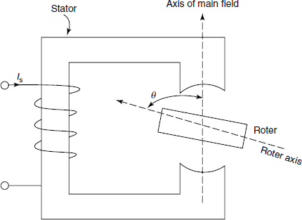
Figure B.1 Reluctance Motor
The stator inductance is expressed by
Lss = L0 + 2L cos2θ (B.1)
This is a function of rotor position θ.
The stator current is
is = Ism sinωt (B.2)
The position of the rotor at any time t is expressed by
θ = ωmt + δ (B.3)
where δ is the initial angle of the rotor wrt stator axis and ωm is the angular velocity of the rotor.
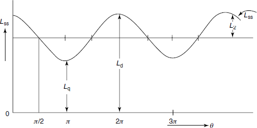
Figure B.2 Variation of Lss with Rotor Position
Figure B.2 shows the variation of stator self-inductance with the position of the rotor. For θ = 0° and θ = 90°, Ld and Lq are the maximum and minimum values of Lss, respectively. Ld represents the direct axis inductance and Lq represents the quadrature axis inductance. The expression for Lis given by
![]()
Here ir = 0 because there is no rotor winding and the torque expression becomes
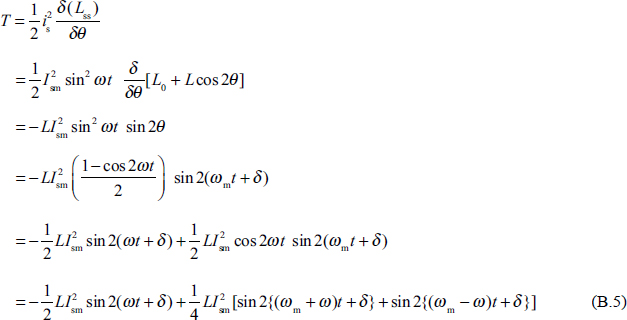
In Equation (B.5), there are three sinusoidal terms. The average value of each of these three sinusoidal terms is zero over a cycle except in certain conditions.
Case 1:
If ωm = 0, we have
![]()
The average torque is
![]()
Case 2:
If ωm = ±ω, we have
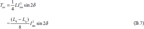
Equation (B.7) shows that the reluctance motor develops average torque when it rotates at a synchronous speed (at the supply frequency) in either direction. The average torque is proportional to sin2δ.
-
No Comment