
Appendix C
MMF of Distributed Winding
The distributed winding in an armature is used in most of the rotating machines. Due to the flow of current in different coils which forms the armature winding, a magnetic field is produced having the same number of poles as the field winding.
The magnetic field’s pattern along the air-gap periphery, which is set up by the distributed winding, is dependent on the following:
- winding arrangement,
- nature of the current flowing through the winding and
- the configuration of the magnetic circuit.
The distribution of air-gap flux in the machine helps to determine the following:
- the wave and magnitude of the generated emf and
- the electrical torque.
The production of mmf by distributed winding in the slots along the airgap periphery is studied at first.
Figure C.1(a) shows that each slot has six conductors where each conductor carries a current ‘i’. Due to the traversing path 1, the ampere-conductor enclosed becomes 2i and the change of mmf has been shown in Figure C.1(b). If the paths 2 and 3 are traversed, the ampere-conductor becomes 4i and 6i, respectively. Figure C.1(b) shows the mmf variation which changes linearly from 0 to 6i over the slot width. Figure C.1(c) shows the simplified form of Figure C.1(b) where the change of mmf is considered stepped at the middle of the slot.
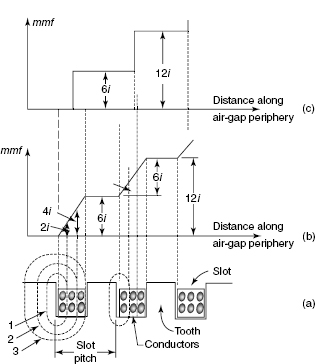
Figure C.1 Mmf by Distributed Winding in the Slots along the Air-Gap Periphery
Figure C.2(a) shows a full-pitched coil on the stator for a two-pole machine having uniform air gap. Let the coil consist of N turns where each turn carries a current ‘i’. The direction of currents has been shown in Figure C.2(a).
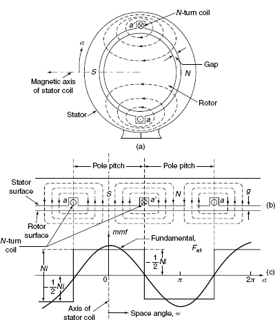
Figure C.2 Full-Pitched Coil and Air-Gap mmf
Figure C.2(b) shows the developed view of Figure C.2(a). The following assumptions are made to sim-plify the analysis:
- The stator and rotor iron have much higher permeability compared to air so that the magnetic flux is offered by the air gap only.
- The magnetic lines of force cross the air gap radially.
As per Ampere’s circuital law, we have
![]() = total current enclosed
= total current enclosed
i.e., 2xH = Ni where ‘x’ is the air-gap length.
Equation (C.1) shows that the magnetic potential difference across the air gap is ![]() Ni. Figure C.2(c) shows the variation of magnetic flux along the air-gap periphery. The magnetic flux leaving the rotor or entering the stator is considered as positive.
Ni. Figure C.2(c) shows the variation of magnetic flux along the air-gap periphery. The magnetic flux leaving the rotor or entering the stator is considered as positive.
Figure C.2(c) shows that the air-gap mmf wave at any instant is rectangular. There is no variation of mmf with time and space when the current in the coil is direct in nature. If it is alternating in nature, mmf varies with time not with space; i.e., it is time variant only.
Using Fourier series, the rectangular mmf waveform having magnitude ![]() Ni can be resolved into its fundamental and higher order components. The fundamental component part becomes
Ni can be resolved into its fundamental and higher order components. The fundamental component part becomes
The alignment of F1p is always with the magnetic axis of the coil.
When ‘i’ is the alternating type, the maximum value of F1p becomes
The maximum value of ‘i’ is Imax = ![]()
For a P –pole machine,
Figure C.3(a) shows three full-pitched coils on the stator, where windings are distributed on it. Let each coil has N turns and each turn carry a current ‘i’. Figure C.3(b) shows the developed view of Figure C.3(a).
Figure C.3((c)(i)) shows the mmf variation for the coil a–á only which is rectangular wave of magnitude ![]() . Figures C.3((c)(ii)) and C.3((c)(iii)) show the mmf variation of coils b–b´ and c–c´, respectively. When the individual mmfs are summed up, the combined mmf can be obtained. From Figure C.3((c)(iv)), the combined mmf to the left of the coil a is
. Figures C.3((c)(ii)) and C.3((c)(iii)) show the mmf variation of coils b–b´ and c–c´, respectively. When the individual mmfs are summed up, the combined mmf can be obtained. From Figure C.3((c)(iv)), the combined mmf to the left of the coil a is ![]() . Its value is
. Its value is ![]() between coil sides a and b, while it is
between coil sides a and b, while it is ![]() between coil sides b and c. The combined value of mmf between coil sides c and a´ is
between coil sides b and c. The combined value of mmf between coil sides c and a´ is ![]() . Figure C.3((c)(iv)) shows the complete combined value of mmf.
. Figure C.3((c)(iv)) shows the complete combined value of mmf.
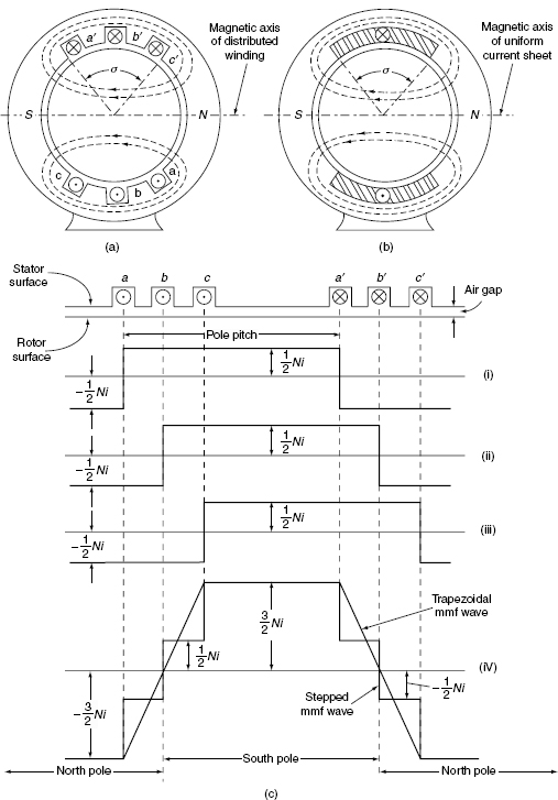
Figure C.3 Full-Pitched Coil, Its Developed View and mmf Variation