1 Transformers
Nowadays, electrical power is generated for industrial and utility purposes by thermal power stations and large hydroelectric plants in the three-phase form at a frequency of 50 Hz (in India). The generated frequency in some other countries is 60 Hz. The generated voltage at the generating station is 6.6 kV, 11 kV or higher. For transmission purposes, it is required to step it up to a voltage of 132 kV or higher. Again, in urban and rural areas it is required to step it down to 3.3 kV and 6.6 kV, respectively, and 11 kV at the substation. For domestic purposes, it is required to step it down to 400 V or 230 V Three-phase transformers are used to step up the generated voltage before transmission of electrical power and also to step down the high voltage before distribution, that is, at the substation. Before the study of three-phase transformers, knowledge of single-phase transformers is essential. The aim of this chapter is to discuss single-phase transformers only.
1.1 DEFINITION
A transformer is a static or stationary electromagnetic device, consisting of two coils, by means of which electrical power in one circuit is transformed into electrical power of the same frequency in another circuit.
1.2 BASIC PRINCIPLE
Figure 1.1 shows a basic single-phase transformer having two windings wound on a common magnetic core. From the principle of mutual induction, when two coils are inductively coupled and the current in one coil is changed uniformly, an emf (electromagnetic force) is induced in the other coil. If a closed path is provided at the secondary circuit, this induced emf at the secondary drives a current. As shown in Figure 1.1, the transformer has two coils, which are electrically separated and magnetically linked through a common magnetic path. The basic principle of the transformer is the same as the principle of mutual induction. The coils of the transformer have high mutual inductance.

Figure 1.1 Transformer
In brief, we can say the following:
- The transformer is a static device.
- It transfers electrical power from one circuit to another.
- During transfer of power, there is no change of frequency.
- It uses electromagnetic induction to transfer electrical power.
- The two electrical circuits are in mutual inductive influence of each other.
1.3 TYPES OF TRANSFORMERS
A transformer may be step up or step down. If the output voltage is greater than the input voltage, the transformer is said to be a step-up transformer. A transformer is said to be a step-down transformer if the output voltage is less than the input voltage. This classification is carried out on the basis of the ratio of input and output voltages. From application point of view, the following transformers are most important:
- Power and distribution transformer: These transformers are used for transmission and distribution of power.
- Autotransformer: These transformers are used to change the voltage within relatively small limits and are used for starting AC motors, and so on.
- Transformers for feed installations with static converters: These are used for converting AC to DC and also DC to AC. The first one is used for rectification purposes and the second one for inversion purposes.
- Testing transformers: These are used to conduct tests at high and ultra-high voltages.
- Power transformers for special applications: These are used in furnaces, welding and so on.
- Radio transformers: These are used in radio engineering and similar purposes.
From frequency range point of view, transformers can be divided as (50–400 Hz) audio transformer, wide band and narrow band transformers and pulse transformers. Transformers can also be divided depending on the number of windings such as two winding (conventional) and single winding known as autotransformer.
1.4 CONSTRUCTION OF SINGLE-PHASE TRANSFORMER
Magnetic core and windings (or coils) are the two basic parts of any transformer. The core is made of silicon or sheet steel with 4 per cent silicon and laminated to reduce eddy current loss. It may be in either square or rectangular shape. It has two parts. The vertical portion on which the coil is wound is called the limb of the core, whereas the top and bottom horizontal portions are called the yoke. Figure 1.2(a) shows the limb and yoke of the core. The permeability of the material used for core must have high value (μr>1,000) to reduce reluctance of the magnetic path.
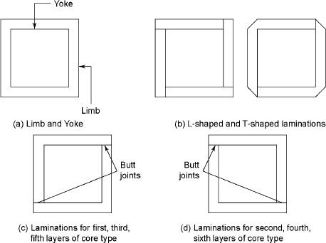
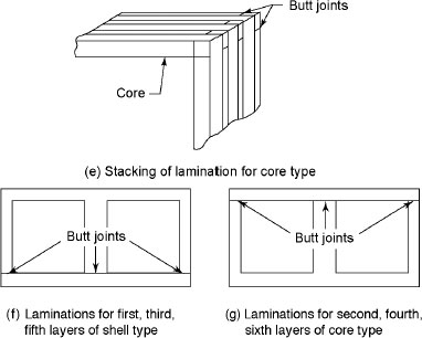
Figure 1.2 Amalgamation of Laminations
The laminations are insulated from each other by a light coat of core plate varnish or by an oxide layer on the surface. The thickness of lamination is 0.35 mm for a frequency of 50 Hz and 0.5 mm for a frequency of 25 Hz. Figure 1.2(b) shows that the joints of the laminations are staggered to avoid the pressure of narrow gaps right through the cross section of the core. Such staggered joints are said to be imbricated. The cross section of the limb depends on the size of the coil. The thickness of the laminations should be small to reduce the eddy current loss. There is a practical limit of the thickness of lamination, which is 0.3 mm. Any further reducing the value of thickness of laminations leads to make them mechanically weak. The range of acceptable thickness of laminations is 0.33–0.50 mm. The laminations are made by grade steel containing 3–5 per cent of silicon, which increases the resistivity of the core leading to reduction of eddy current core loss. This high-content silicon steel is a soft iron material, which has narrow hysteresis loop and a high permeability. This causes reduction of hysteresis loss and magnetizing current. The steel used for transformer core are either hot rolled or cold rolled. The maximum value of flux density permitted to hot-rolled steel is 1.45 Wb/mm2. The maximum value of flux density permitted to cold-rolled steel is 1.8 Wb/m2, and it is 25–35 per cent more expensive than the hot-rolled steel. The cold-rolled grain-oriented (CRGO) steel sheet with a silicon content of 3 per cent is also used for magnetic circuits of transformer. In a magnetic circuit, we know that flux = mmf/reluctance = primary ampere turns/reluctance, which suggests that the requirement of primary ampere-turns are less for a given value of flux when the reluctance is low. To avoid the joints to come in same line, the laminations of the core are arranged in the form of stack. To achieve this, the laminations shown in Figures 1.2(c) and 1.2(d) are put in alternate layers of Figure 1.2(e) for core-type laminations. Figures 1.2(f) and 1.2(g) shows the laminations for obtaining the shell-type transformers.
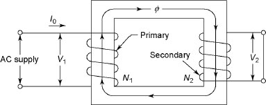
Figure 1.3 Two-winding Transformer
The two windings are wound on two limbs, that is, one on the primary and the other on the secondary, as shown in Figure 1.3. Leakage flux increases in this connection. This leakage flux has a negative effect on the transformer performance. To get high mutual inductance, the two coils must be close to each other. To obtain this, the two windings are divided into a number of coils and wound adjacent to each other on the same limb, as shown in Figure 1.4.
In Figure 1.4, the common arrangement is of cylindrical coils, which are used in the core-type transformers. These coils are mechanically strong and are wound in the helical layers where different layers are insulated from each other by paper, cloth or mica. The low-voltage winding is generally placed heat to the core because it is easier to insulate the low-voltage winding. The high-voltage wind-ing is placed after it. Due to laminations and insulation, the net effective core area is reduced and this reduction is generally in the order of 10 per cent. The other type of winding is generally used for the shell-type transformer known as sandwich coils (shown in Figure 1.5). Since each high-voltage portion lies between two low-voltage portions, the two low-voltage portions sandwich the high-voltage portion. The leakage flux is reduced due to subdivision of windings into small portions. The top and bottom portions are low-voltage coils and all portions are insulated from each other by paper.
Transformers are classified into the following three categories based on the relative arrangement or disposition of the core and the winding: (i) Core type, (ii) shell type and (iii) spiral core type.
1.4.1 Core Type
Figure 1.6(a) shows the complete magnetic circuit of a core-type transformer in the shape of a hollow rectangle having two limbs. It has a single magnetic circuit. In Figure 1.6, I0 is the no-load current and Φ is the flux produced by it. Number of turns of the primary and secondary are N1 and N2, respectively.
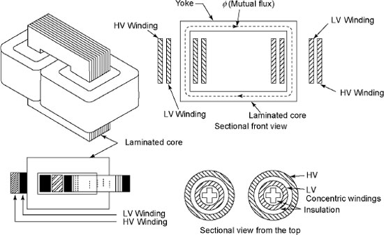
Figure 1.4 Schematic and Sectional View of a Core-type Transformer
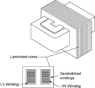
Figure 1.5 Schematic View of a Shell-type Transformer
The windings surround the core. The coils used are wound and are of cylindrical type having the general form circular, oval or rectangular.
Core-type transformer has a longer mean length of core and a shorter mean length of coil turn. Core has a small cross section of iron; more number of turns is required because the high flux may not reach the core. Core type is used for high-voltage service, since it has sufficient room for insulation.
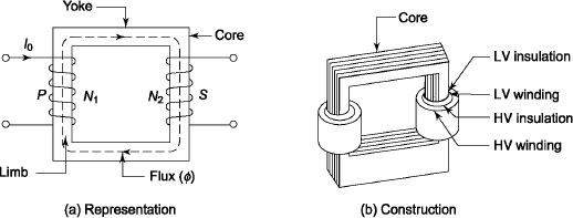
Figure 1.6 Core-type Transformer

Figure 1.7 Different Cross Sections of Core-type Transformer
Figure 1.6(b) shows the actual view of a core-type transformer. The different cross sections used in core-type transformer are shown in Figure 1.7.
In small core-type transformers, rectangular cores with rectangular cylindrical coils are used as shown in Figure 1.7(a), whereas circular cylindrical coils are used for large transformers; hence, square cores are preferred as shown in Figure 1.7(b). If rectangular cores are used for large transformers, it becomes wasteful. Figure 1.7(c) shows the cruciform core, which is an improvement of square core. Figure 1.7(d) shows further core stepping (three-stepped cores) for large transformers resulting in reduced length of mean turn and copper (Cu) loss.
1.4.2 Shell Type
Shell-type transformer has double magnetic circuit and three limbs. Both windings are placed on the central limb. The coils occupy the entire space of windows. The coils are usually multi-layer disc type or sandwich coils. The low-voltage coils are placed nearest to the iron core to reduce the amount of high-voltage insulation. Core is laminated. Special care is taken to arrange the laminations of the core. All the points at alternate layers are staggered properly to avoid narrow air gap at the joint, right through the cross section of the core. The joints are known as overlapped or imbricated joints. The shell-type construction is preferred for a few high-voltage transformers. Since the windings are surrounded by core, natural cooling does not exist. To remove any winding during maintenance, removal of a large number of laminations is required. Figure 1.8 shows a shell-type transformer.
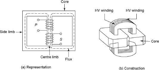
Figure 1.8 Shell-type Transformer
Due to better provision for mechanical support and bracing of coils in the shell-type transformer, better resistance to combat high mechanical force is obtained. High mechanical forces are developed for a high current during short circuit.
1.4.3 Spiral Core Type
Figure 1.9 shows spiral core-type transformer where the core is assembled either of a continuous strip of the transformer steel wound in the form of a circular or elliptical cylinder or of a group of short strips assembled to produce the same elliptical shape. In this construction, the core flux always follows along the grain of iron. Cold-rolled steel of high silicon content allows the designer to use higher operating flux densities with lower loss per kilogram. The main advantage of using the higher flux density is that weight/kVA is reduced.
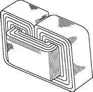
Figure 1.9 Spiral Core-type Transformer
1.5 TRANSFORMER WINDINGS
There are two types of windings usually used in a transformer. The winding receiving electrical energy is known as primary winding, whereas the winding delivering electrical energy is called secondary winding. Windings are usually made of high grade of copper. Standard conductors are used for carrying higher current. To avoid the each turn to come in contact with each other, the windings are provided with insulation. In addition to inter-turn insulator, bare copper wires are provided with enamel coating. Usually single- or double-layer cotton is used. Sometimes press board or cotton insulation is also used to support the windings. Usually additional insulation is provided for line end turns for their protection from lightning and switching over voltages. During transient disturbances, the distribution of voltage is not uniform along the windings and 80 per cent of voltage at that time appears across the first 10 per cent of turns from line end. Heat generation occurs due to energy loss, which is proportional to the volume of the material in which the losses occurs. The heat dissipation is proportional to the surface area of the same material and the tank. The ratio of heat generated to heat dissipated is approximately proportional to the ratio of volume of the material for conductors and the core to the surface area of the material for conductors, the core and the tank, which must approach to unity to limit the temperature rise. This can be achieved by corrugating the surface area of the tank. To get effective cooling, the radiators are used shown in Figure 1.18 later on.
The following are the most important requirements of transformer windings:
- The windings must be economical.
- The heating conditions of the windings should satisfy standard requirements.
- The windings must have good mechanical strength to combat the force that originates due to short circuit.
- The windings must have the necessary electrical strength during over-voltage. The following are the two different types of windings: (i) Concentric windings and (ii) sandwich windings.
1.5.1 Concentric Windings
Figure 1.10 shows concentric windings, which are used for core-type transformers.
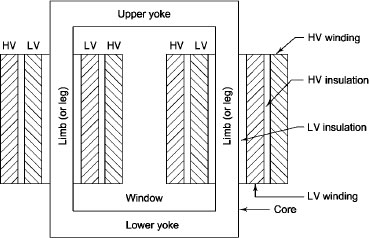
Figure 1.10 Concentric Windings
Concentric windings are classified into four following groups:
(i) Spiral windings.
(ii) Helical windings.
(iii) Cross-over windings.
(iv) Continuous disc windings.
These windings are discussed as follows.
1.5.1.1 Spiral Windings
These coils are suitable for windings to carry high currents, which are generally used or currents greater than 100 A. They are almost used for LV windings. Figure 1.11 shows double-layer spiral coils, which are wound on solid insulating former, and hence are mechanically strong.
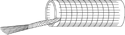
Figure 1.11 Double-layer Spiral Coil
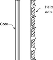
Figure 1.12 Helical Coils
1.5.1.2 Helical Windings
These coils are wound in the form of helix, which are generally used for low voltages 11 kV to 33 kV for large transformers. Figure 1.12 shows the cross-sectional view of helical coils where each conductor consists of a number of rectangular strips wound in parallel radially.
1.5.1.3 Cross-over Windings
These coils are generally wound on formers. Each coil consists of several layers and each layer consists of several turns. Figure 1.13 shows cross-over coils. The conductors may be of round wire with paper or cotton insulation and not suitable for currents exceeding 20 A. These coils are generally used for small transformers and for HV windings.
1.5.1.4 Continuous Disc Windings
Figure 1.14 shows disc coils. These windings consist of a number of disc and each disc consists of number of turns wound radially over one another from inside outwards and outside inwards alternately. Conductor consists of single number of rectangular strips and passes continuously from disc to disc for multiple strip of conductors. The transposition of conductors is done to ensure uniform current distribution. These windings are mechanically strong and hence can withstand stresses during short circuit conditions. These are used for HV windings of large power transformers.
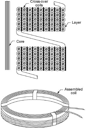

Figure 1.14 Disc Coils
1.5.2 Sandwich Windings
Figure 1.15 shows sandwich windings used in shell-type transformers. The high-voltage and low-voltage windings are split into a number of sections where each high-voltage section lies between two low-voltage sections. In sandwich coils, easily leakage can be controlled. Desired value of leakage reactance can be obtained by proper division of windings.
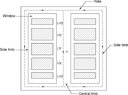
Figure 1.15 Sandwich Windings
1.6 TERMINALS AND LEADS
Insulated copper bars or rods are used for the connections to the windings. High electric stress and corona at bends and corners occur in high-voltage transformers. Therefore, the shape and size of leads are most important in high-voltage transformers. Sharp edges and corners should be avoided to reduce dielectric stress and corona.
1.7 BUSHINGS
Transformers are connected to high-voltage lines. Extreme care is required to prevent flashover from the high-voltage connection to earthed bank. Bushings are used to insulate and bring out terminals of the winding from the container to the external circuit. For transformers upto 33 kV, this is achieved by using bushings of porceling around the conductor at the point of entry. For transformers above 33 kV, either oil-filled or capacitor-type bushings are used.
1.8 TAPPING
By changing the turns ratio of the transformer, we can easily control the voltage supplied to power networks by the transformer. To affect a change in the ratio of transformation, we provide tapping at different places in the windings of the transformer. Therefore, it is possible to get different turns ratio and thus different voltages at different tappings. Figure 1.16 shows the tapping used in a transformer.
For a three-phase, 11,000/400 V distribution transformer, there is always tapping on the high-voltage winding. If 11,000 V supply is given on the high-voltage side, 400 V is obtained on the low-voltage side. This tapping is known as principal tapping. The tapping at which the number of turns included is more than or less than the number of turns included at principal tapping is known as positive and negative tapping, respectively.

Figure 1.16 Tapping
1.9 COOLING OF TRANSFORMER
Transformer is a static device that converts one voltage level to another voltage level. Due to occurrence of iron and copper losses, the transformer gets heated. In order to avoid deterioration of insulation, dissipation of heat is required to keep the temperature of the winding within a limited value. Since transformer is a static device, its cooling is more difficult than that of a rotating machine. Rotating machine creates a turbulent air flow, which helps in removing the heat generated due to losses. The losses in a transformer are comparatively small. The coolants used in transformer are: (i) air and (ii) oil.
The dry-type transformer uses air as coolant, whereas oil-immersed transformer uses oil as cool-ant. The heat produced in dry-type transformers is conducted across the core and windings. Finally, the heat dissipates from the outer surfaces of the windings to the surrounding air through convection. The heat generated inside the core and windings of an oil-immersed transformer is conducted across them to their surfaces. This heat produced is transferred by the oil to the walls of the tank through convection.
The cooling methods used in transformers up to 25 kVA size and of dry type are discussed below:
- Natural air: Ambient air is used as the cooling medium in this method, and the natural circulation of surrounding air is used to carry away the generated heat by natural convection.
- Air blast: Natural circulation of air used in cooling becomes insufficient for dissipation of heat from large transformers. Therefore, circulation of air (air blast) is used to keep the temperature rise within prescribed limits. A continuous blast of cool air is forced through the cores and the windings to cool the transformer in this method. External fans are used to produce air blast shown in Figure 1.17(a).
Generally most of the transformers are of oil-immersed types because oil provides better insulation than air due to its better conduction heat. Mineral oil is used for this purpose. The following cooling methods are used for oil-immersed transformers.
- Oil-immersed self-cooled transformers: The transformer is immersed in oil. The heat generated in cores and windings is passed to the oil by conduction. Therefore, oil in contact with the heated parts rises and cool oil takes its place. The heat is transferred to the tank walls by natural oils.
Figure 1.17 Air Blast and Oil-immersed Self-cooled Transformer
Figure 1.18 Air Blast Cooling for High-capacity Transformers
Finally, ambient air takes this heat. To increase the heat dissipating capacity, corrugations, fins, tubes (shown in Figure 1.18) and radiators are to be provided in Figure 1.17(b). In oil natural cool-ing, there is no chance to clog the ducts and hence windings are free from the effects of moisture.
- Oil-immersed forced air-cooled transformers: In this method, air is directed over the outer surfaces of the tank of the transformer immersed in oil.
- Oil-immersed water-cooled transformers: In this type of cooling, water is pumped through a metallic coil immersed in the oil just below the top of the tank to extract heat from the oil. The heated water is cooled in a spray pond or a cooling tower.
- Oil-immersed forced oil-cooled transformers: To extract heat from the oil, oil itself is pumped upwards through the winding. Then it is sent back by way of external radiators. These radiators are cooled by fans. The extra cost of pumping equipment should be justified economically. The main advantage is the reduction in temperature difference between the top and the bottom of the enclosing tank. Figure 1.18 shows the schematic arrangement of air blast cooling used for high-capacity transformers.
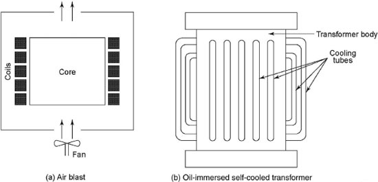
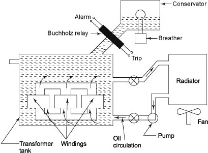
Table 1.1 summarizes methods of cooling of transformers.
Table 1.1 Methods of Cooling of Transformers

1.10 TRANSFORMER OIL
Transformer oil is a mineral (clean hydrocarbon) oil, which is obtained by refining crude petroleum. It has the following purposes:
- It provides additional insulation.
- It carries away the heat generated in the core and the coils.
- It protects the paper from dirt and moisture.
Transformer oil has the following properties:
- High dielectric strength.
- Low viscosity to provide heat transfer.
- Good resistance to emulsion.
- It must be free from inorganic acid, alkali and corrosive sulphur.
- It must have high flash point.
- It must be free from sludging under normal operating conditions.
The most important factors are:
- Operating temperature.
- Atmospheric conditions, particularly inside stations.
- Electric strength.
- Moisture and other contamination.
- Sludge formation.
1.11 CONSERVATOR AND BREATHER
Satisfactory operation of a transformer solely depends on the condition of the oil. It is required to keep the oil clean and dry. With the rise of temperature, the oil level increases. Rise of temperature depends on the load of the transformer. If load increases, oil expands. If load decreases, contraction of oil occurs. Since smaller transformers are not totally filled by oils, some space is left between tank walls and oil, which is occupied by air. The tank is connected to the atmosphere through a vent pipe. Air is expelled out if oil expands. Air is drawn from the atmosphere if oil contracts. When air enters the transformer, it is required to extract moisture from the air. An apparatus known as breather is used to extract moisture from the air. It is a small container connected to the vent pipe containing a dehydrating material such as silica gel crystal impregnated with cobalt chloride. The colour of the material is blue when it is dry. It becomes whitish pink when it is damp. In front of the container, a glass window is provided to observe the colour of the material.
If the transformer becomes overloaded, it overheats the oil and sludge formation occurs in the presence of air. If transformer suffers short circuit, temperature rise becomes very high and this causes vaporization of a part of the oil, which forms an explosive mixture with air. This explosive mixture can ignite and cause considerable damage. To prevent the air coming in contact with air as well as moisture, conservators are used. It takes the responsibility of expansion and contraction of oil without allowing it to come into contact with air. The conservator is an air-tight cylindrical drum mounted on or near the cover of the transformer. It is connected to the transformer through a small pipe. In Figure 1.18, breather and conservator are shown.
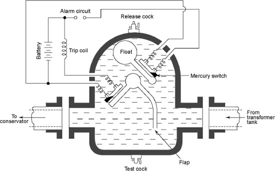
Figure 1.19 Buchholz Relay
1.12 BUCHHOLZ RELAY
Figure 1.19 shows Buchholz relay having two elements mounted in a small chamber. It is located in the pipe connection between the conservator and the transformer tank. Heat is produced due to leakage current for any minor fault and some of the oil in the transformer tank evaporates. Some vapour comes to the top of the chamber while passing through to the conservator. The oil level falls due to accumulation of vapour, and the mercury tape attached to the float is tilted closing the alarm circuit to ring the bell. A release cock is attached to the top of the chamber to release the pressure of the chamber after operation and gas is emitted. It allows refilling of oil in the chamber once again. During severe fault, a large volume of gas is evolved, which tilts the lower element containing a mercury switch mounted on a hinged-type flap and the trip coil is energized. A test cock is provided at the bottom of the chamber, which allows air to be pumped into the chamber for test purposes.
1.13 TRANSFORMER TANK
The factors such as weight, stray load losses and minimum cost are kept in mind while selecting the material for transformer tank. The material must be capable to withstand stresses due to jacking and lifting and must have capacity to house cores, windings and internal connections giving adequate clearance between the windings and the walls. Rolled steel plates are used for tank bodies of most of the transformers. Small tanks are generally welded from steel plates. The larger tanks are assembled from boiler plates. Usage of aluminium for transformer tank reduces the weight and the stray magnetic losses. However, it increases the cost and also needs special attention for lifting to present stressing. The aluminium tanks are usually made of cast aluminium tank parts, which are mounted on a shallow mild steel tray and are arranged to carry the main lifting.
1.14 THEORY OF TRANSFORMER
Figure 1.20 shows the elementary diagram of an ideal transformer with secondary side open circuited. It has no ohmic resistance and leakage reactance. There is no loss in an ideal transformer. In Figure 1.16, alternating voltage (V1) is applied at the primary and hence alternating current flows in the primary. The primary draws the magnetizing current Iμ only because it is purely inductive in nature. Iμ is small in magnitude and lags behind V1 by an angle 90°. The function of Iμ is to magnetize the core, and it produces an alternating flux (Φ), which is proportional to Iμ. The alternating flux (Φ) is linked with both primary and secondary windings and causes self-induced emf (E1) in the primary. This self-induced emf (E1) is equal and opposite to V1 at every instant. This induced emf is known as back emf or counter emf. Due to mutual induction, an emf E2 is produced in the secondary. This emf is known as mutually induced emf. It is anti-phase with V1 and its magnitude is proportional to the rate of flux as well as the number of turns of the secondary windings.
Figure 1.21(a) shows the instantaneous values of applied voltage, induced emfs, flux and magnetizing current by sinusoidal waves, while Figure 1.21(b) shows the vectorial representation of the effective values of the above quantities.
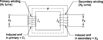
Figure 1.20 Elementary Diagram of an Ideal Transformere

Figure 1.21 Instantaneous Values and Vectorial Representation
1.15 EMF EQUATION OF A TRANSFORMER
Figure 1.22 shows the representation of alternating flux, varying sinusoidally, which increases from its zero value to maximum value (Φm) in one-quarter of the cycle, that is in one-fourth of a second where f is the frequency of AC input in hertz.
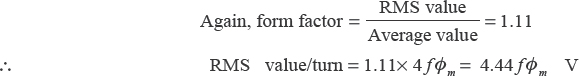
The average rate of change of flux is given by ![]() , that is 4fΦm Wb/s or V.
, that is 4fΦm Wb/s or V.

Figure 1.22 Representation of Alternating Flux
This rate of change of flux per turn is the induced emf in V.
Therefore, average emf/turn = 4fΦmm V.
Let N1 and N2 be the number of turns in primary and secondary.
The rms value of induced emf in primary winding is given by
E1 = (4.44fΦm m) × N1 = 4.44fΦm mN = 4.44f BmArN1 (1.1)
where ![]() is the maximum value of flux density having unit Tesla (T) and Ar is the area of cross-section.
is the maximum value of flux density having unit Tesla (T) and Ar is the area of cross-section.
Similarly, RMS value of induced emf in secondary winding is
E 2 = (4.44fΦm )x N2 = 4.44fΦmN2 = 4.44f BmArN2 (1.2)
From Equations (1.1) and (1.2), we have
where ‘a’ is the turns ratio of the transformer,
Equation (1.3) shows that emf induced per turn in primary and secondary windings are equal.
In an ideal transformer at no load, V1 = E1 and V2 = E2, where V2 is the terminal voltage of the transformer. Equation (1.3) becomes
Example 1.1 The voltage ratio of a single-phase, 50 Hz transformer is 5,000/500 V at no load. Calculate the number of turns in each winding if the maximum value of the flux in the core is 7.82 mWb.
Solution
Here
E1 = V1 = 5,000 V
E2 = V2 = 500 V
φmax = 7.82 m Wb = 7.82 × 10⁻³ Wb, f = 50Hz
Let N1 and N2 be the number of turns of the primary and secondary windings, respectively.
Since
E1 = 4.44 f φm N1
![]()
i.e., ![]()
Again, ![]()
∴ ![]()
Example 1.2 A single-phase transformer is connected to a 800 V supply. The voltage/turn of the transformer is 8 V The secondary voltage of the transformer is found to be 400 V Determine the following:
(i) Primary and secondary turns.
(ii) Cross-section of the core if the maximum flux density is 1.4 T.
Solution
Here Voltage/turn = 8 V, E1 = 660 V, E2 = 440 V, Bmax =1.4 T
(i) ![]()
Therefore, the number of primary and secondary turns is 100 and 50, respectively.
(ii) Again EM1 = 4.44 f N1 Bmax Ar
i.e., ![]()
Example 1.3 The cross-section of the core ofa4 kVA, 5,000/500 V, 50 Hz, single-phase transformer having maximum flux-density 1.5 T is 500 cm2. Determine the following:
(i) The number of turns of primary and secondary windings.
(ii) The emf per turn.
The stacking factor of the core is 0.85.
Solution
Here Ar = 500 cm2 = 500 × 10-4 m2, Bmax = 1.5 T, f= 50 Hz, E1, = 5,000 V, E2 = 500 V, stacking factor = 0.85.
1.16 STEP-UP AND STEP-DOWN TRANSFORMER
From Equation (1.6), we have
![]()
If N1 > N2, V1 > V2, that is the output voltage is less than the primary voltage. The transformer is said to be a step-down transformer.
If N1 < N2, V1 < V2, that is the output voltage is greater than the primary voltage. The transformer is said to be a step-up transformer.
For an ideal transformer, input VA = output VA
∴ V1V1=V2I2
i.e., ![]()
Comparing Equations (1.6) and (1.7), we can conclude that currents are in inverse ratio of turns ratio.
Example 1.4 A 50 kVA, single-phase transformer has 500 turns on the primary and 100 turns on the secondary. The primary is connected to 2,500 V, 50 Hz supply. Calculate the following:
(i) The secondary voltage on open circuit.
(ii) The current flowing through the windings on full load.
(iii) The maximum value of flux.
Solution

∴
∴ The secondary voltage on open circuit is V2 = E2 = 500 V.
- kVA rating the transformer = 50 kVA
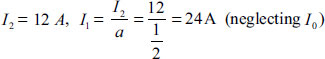
Primary full-load current (I1)=
Secondary full-load current (I2)=
- Again, E1 = 4.44fΦmaxN1
i.e., Φmax=
1.17 TRANSFORMER ON NO LOAD
For an ideal transformer, we have assumed that there are no core losses and copper losses. For practical transformers, these two losses cannot be neglected. At no-load condition, the primary current is not fully reactive and it supplies (i) iron loss in the core, that is, hysteresis loss and eddy current loss and (ii) very small amount of copper loss in the primary. There is copper loss in the secondary because it is an open circuit. The no-load current lags behind V1 by an angle θ0, which is less than 90° (around 80°–85°). The no-load input power is given by
where cosθ0 is the no-load power factor. Figure 1.23 shows the no-load phasor diagram of a practical transformer. From Figure 1.23, the no-load primary current (I0) has the following two components:
- One component of I0, that is Iw = I0 cosθ0 is in phase with V1. Since Iw supplies the iron loss and primary copper loss at no load, it is known as active or working or iron loss component.
- The other component of I0 that is, = I0 sinθ0 is in quadrature with V1. It is known as magnetizing component. Its function is to sustain the alternating flux in the core and it is wattless.
From Figure 1.23, we have
The following points are most important:
- The no-load primary current is 1–5 per cent of full-load current.
- Since the permeability of the core varies with the instantaneous value of exciting or magnetizing current, the waveform of exciting or magnetizing current is not truly sinusoidal.
- Since I0 is very small, the no-load copper loss is negligible. Hence, no-load input is practically equal to the iron loss in the transformer.
- Since core loss is solely responsible for shifting the current vector I0, the angle θ0 is known as hysteresis angle of advance.
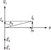
Figure 1.23 Phasor Diagram at No-Load
Figure 1.24 shows the equivalent circuit of the transformer at no load.
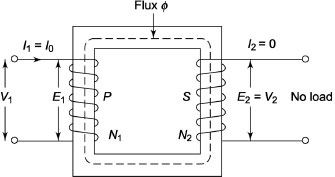
Figure 1.24 Equivalent Circuit of Transformer at No-load
Example 1.5 The no-load current of a 4,400/440 V, sinlge-phase, 50 Hz transformer is0.04. It consumes power 80 W at no load when supply is given to LV side and HV side is kept open. Calculate the following:
(i) Power factor of no-load current.
(ii) Iron loss component of current.
(iii) Magnetizing component of current.
Solution
W0 W, I0 =0.04 A, V1 = 4,400 V
- Since W0 = V1I0cosθ0
The no-load power factor is 0.454 (lagging).
- IW = I0 cosθ0 =0.04 × 0.454 = 0.0187 A

∴ Iμ = I0 sinθ0 = 0.04 × 0.891 = 0.0356
Example 1.6 A 2,200/220 V, 20 kVA, single-phase transformer takes a no-load current of1.3 A when high-voltage winding is kept open. The iron loss component of no-load current is equal to 0.5A. Calculate the following:
- No-load input power
- Magnetizing component and power factor of no-load current.
Solution
Given
I0 = 1.3 A, IW = I0 cosθ0 = 0.5 A
V1 = E1 = 2,200 V and E2 = V2 = 220 V
- No-load input power (W0) = V2 I0 cosθ0 = V2 IW = 220 × 0.5 = 110 W.

∴sinθ0=

∴Iμ=I0sinθ0=1.3 × 0.923 = 1.199A
1.18 TRANSFORMER ON LOAD
Figure 1.25(a) shows the transformer during no-load condition. The flux Φ is set up in the core. When the secondary is loaded shown in Figure 1.25(b), the secondary current will set up its own flux (Φ2), which opposes Φ. The resultant flux becomes Φ – Φ2. The value of e1 will decrease because magnitude of Φ decreases. Hence, v1 becomes greater than e1 and the primary winding draws more current from the source. Let the additional current drawn by the primary be I2′. This current I2′ will set up its own flux (Φ2′) in the same direction of Φ and it will oppose Φ2 shown in Figure 1.25(c). The resultant flux will be Φ at any load condition if and only if
Φ2′=Φ2
i.e., N1I2′=N2I2
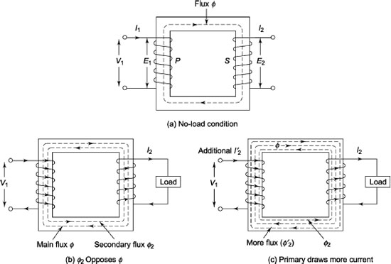
Figure 1.25 On-load Transfer
1.19 EQUIVALENT RESISTANCE
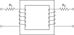
Figure 1.26 Individual Resistances
Figure 1.26 shows a transformer having primary resistance R1 and secondary resistance R2, where resistances have been shown external to the wind-ings. In Figure 1.26, it is assumed that there is no fringing, i.e. no leakage of flux. It is possible to transfer resistance from one winding to another to simplify the calculation. Let N1 and N2 be the number of turns of primary and secondary winding respectively. Let the turns ratio be ‘a’. Let I1 and I2 be the currents in primary and secondary winding, respectively. Neglecting I0, ![]() = a. Let the referred value of R2 be R2′ when it is transferred to primary. The copper loss of secondary is I22R2 when R2 is in secondary. The copper loss across R2′ is I12R2′ when R2 has been transferred to primary. These two losses must be equal.
= a. Let the referred value of R2 be R2′ when it is transferred to primary. The copper loss of secondary is I22R2 when R2 is in secondary. The copper loss across R2′ is I12R2′ when R2 has been transferred to primary. These two losses must be equal.
∴ I22R2=I12R2′
The total resistance referred to as primary becomes R1 + R2′ or R1 + a2R2. This is also known as equivalent or effective resistance of the transformer referred to as primary and is denoted by R01.
Figure 1.27 is the equivalent of Figure 1.26 when the secondary resistance is transferred to the primary.
If R1 is transferred to secondary, having referred value R1′, we have
I12R1=I22R1′
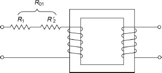
Figure 1.27 Resistance Referred to as Primary
Therefore, the equivalent resistance of the transformer referred to as secondary becomes
Figure 1.28 is the equivalent of Figure 1.26 when the primary resistance is trans-ferred to the secondary.
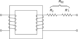
Figure 1.28 Resistance Referred to as Secondary
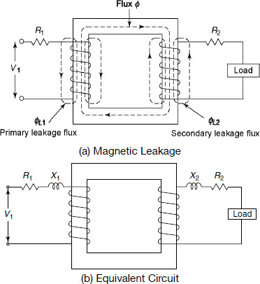
Figure 1.29 Magnetic Leakage and Equivalent Circuit
1.20 MAGNETIC LEAKAGE
Till now we have assumed that all the flux linked with the primary also links with the secondary. But in practice, the permeability of the core of the transformer is finite. All the flux linked with the primary do not link with the secondary. As shown in Figure 1.29(a), ΦL1 and ΦL2 induce emf eL1 and eL2 in primary and secondary windings respectively. Therefore, in effect, we can consider it as an equivalent inductive coil in phase with the winding shown in Figure 1.29(b).
1.21 EQUIVALENT REACTANCE
If X2 be transferred to primary, let its referred value be X2′. We have
I22X2=I12X2′
If X1 be transferred to secondary, let the referred value be X1′ We have
I12X1=I22X1′
The total reactance referred to as primary (X01) is Xl + a2 X2 and that of referred to as secondary (X02) is X2+![]() . The total reactance is known as equivalent reactance. It is denoted by
. The total reactance is known as equivalent reactance. It is denoted by
Example 1.7 A 30 kVA, 3,000/300 V, 50 Hz, single-phase transformer has the following winding resistances (R’s) and leakage reactances (X’s):
Calculate the following:
R1=2.5Ω R2=0.018Ω
X1=3.8Ω X2=0.052Ω
Calculate the following:
- Equivalent resistance, leakage reactance and impedance referred to as high-voltage side.
- Equivalent resistance, leakage reactance and impedance referred to as low-voltage side.
- Total Cu loss of the transformer at full load condition.
Solution
Here R1 = 2.5 Ω, R2 = 0.018 Ω, X1 = 3.8 Ω, X2 = 0.052 Ω.
![]()
- Equivalent resistance referred to as HV side:
R01 = R1 + a2 R2 = 2.5 + (10)2 × 0.018 = 4.3Ω
Equivalent leakage reactance referred to as HV side:
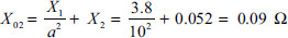
X01 = X1 + a2 X2 = 3.8 + (10)2 × 0.052 = 9Ω
Equivalent impedance referred to as HV side:

- Equivalent resistance referred to as LV side:

Equivalent reactance referred to as LV side:
Equivalent impedance referred to as LV side:

- Total Cu loss at full load:
Primary current(I1)=
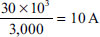
Secondary current(I2)=
Total Cu loss = I12 R01 = (10)2 × 4.3 = 430 W
Also, Total Cu loss = I22 R02 = (100)2 × 0.043 = 430 W
Also, Total Cu loss = I12 R1 + I22 R2 = 102 × 2.5 + 1002 × 0.018 = 430 W.
1.22 TRANSFORMER WITH RESISTANCE AND LEAKAGE REACTANCE
Figure 1.30 shows a transformer having resistances R1 and R2 of primary and secondary windings respectively, and leakage reactances X1 and X2 of primary and secondary windings respectively. The primary impedance is given by
and the secondary impedance is given by
The applied voltage V1 on primary side is given by
If V2 be the secondary terminal voltage during load, the secondary induced emf (E2) is given by
Figure 1.31 shows the phasor diagram of the transformer for unity power factor, lagging power factor and leading power factor respectively.
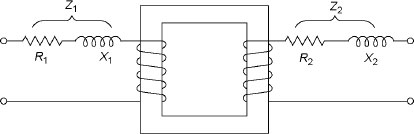
Figure 1.30 Transformer with Resistance and Leakage Reactance
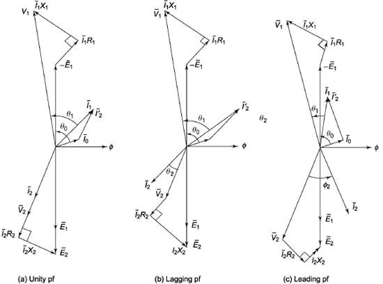
Figure 1.31 Phasor Diagram of a Transformer at Load
1.23 EQUIVALENT CIRCUIT
Figure 1.32 shows the equivalent circuit of a single-phase transformer having load impedance ZL. Figure 1.33 is the equivalent circuit of Figure 1.32. The secondary winding resistance (R2), leakage reactance (X2) and load impedance (ZL) connected to secondary terminal is transferred to primary side.
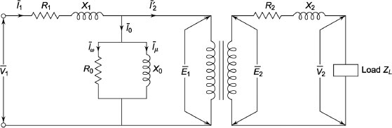
Figure 1.32 Equivalent Circuit

Figure 1.33 Exact Equivalent Circuit
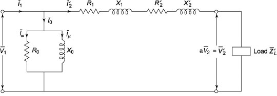
Figure 1.34 Approximate Equivalent Circuit
Since I0 is small compared to full-load current, we can shift the excitation circuit towards the terminal voltage side shown in Figure 1.34. Figure 1.34 is the approximate equivalent circuit, whereas Figure 1.33 is the exact equivalent circuit of Figure 1.32.
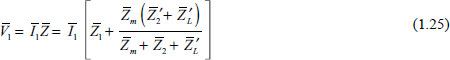
From Figure 1.33, the total input impedance between input terminals becomes
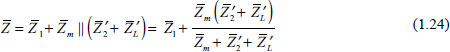
where ![]()
and ![]() is the impedance of the exciting circuit.
is the impedance of the exciting circuit.
R0, X0, R01 and X01 are the four important parameters of the transformer. From open circuit and short circuit test of a transformer, R0, X0 and R01, X01 can be determined respectively.
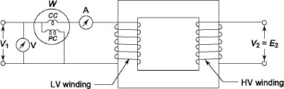
Figure 1.35 Open Circuit Test
1.24 OPEN CIRCUIT TEST OR NO-LOAD TEST
From this test, we can determine core loss and no-load current (I0) of the transformer. Figure 1.35 shows the schematic diagram of the transformer. The high-voltage side is generally kept open because the current in high-voltage winding is less compared to that on low-voltage winding. In low-voltage side, a voltmeter, an ammeter and a wattmeter are connected to measure the input voltage, no-load current and the core loss of the transformer. Since no-load current is generally small, the copper loss at no-load condition is negligible. The wattmeter reading practically gives the iron loss of the transformer.
To measure the induced emf in secondary winding, a high-resistance voltmeter is connected across the secondary to calculate the turns ratio (a).
Let I0 be the reading of the ammeter, V1 be the reading of the voltmeter and W be the reading of the wattmeter.
We have W=V1I0cosθ0
During no-load condition, the voltage drop across the primary impedance is small. Therefore, we have
The total iron loss depends on the frequency as well as the maximum flux density. Hysteresis loss and eddy current loss are the two parts of the total iron loss, which are described below.
where k1 and k2 are the constants in the above two equations, which can be obtained from the experi-ment. The hysteresis and eddy current losses can be calculated by knowing k1 and k2. Figure 1.36 shows the variation of iron loss with the applied voltage.

Figure 1.36 Variation of Iron Loss with Applied Voltage
1.25 SHORT CIRCUIT OR IMPEDANCE TEST
The main purpose of this test is to compute the following:
- Equivalent impedance of the transformer referred to primary and secondary.
- Cu loss of the transformer at any desired load.
- Total voltage drop of the transformer referred to primary and secondary.
Figure 1.37 shows the schematic diagram for the short circuit test of a transformer in which the low-voltage winding is short-circuited. During the short circuit test, we apply 5–10 per cent of the rated voltage to high-voltage side so that the full-load current flow both in primary and secondary. Voltage is slowly increased from zero to a value to get full-load current to flow. Since 5–10 per cent of rated voltage at the primary is easier to achieve smoothly and read by a voltmeter, instruments are always placed on the high-voltage side. A voltmeter, an ammeter and a wattmeter are placed on the high-voltage side. The low-voltage side is directly short-circuited by a thick conductor or by an ammeter.
Let PSC be the reading of the wattmeter, ISC be the reading of the ammeter and VSC be the reading of the voltmeter.
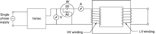
Figure 1.37 Short Circuit Test
Example 1.8 A 4 kVA, 400/200 V, 50 Hz, single-phase transformer has the following test data
OC test: 200V, 2A, 90W
SC test: 20V, 10A, 100W
The instruments during SC test are placed on the side opposite to that of OC test. Find equivalent circuit referred to as primary side (high-voltage side).
Solution
OC test:
Since rated voltage is applied during OC test, instruments are placed on the low-voltage side.
![]()
No-load current(I0) = 2A = (I0)lv
∴ ![]()
Applied voltage at no load = 400 V [for OC Test]
V0I0cosθ0 = 90
i.e., 400 × 1× cosθ0 = 90
i.e., ![]()
∴![]()
∴ IW = I0 cosθ0 = 1 × 0.225 = 0.225 A
and Iμ = I0 sinθ0 = 1 × 0.974 = 0.974 A
∴ ![]()
SC test:
As per the given statement, the instruments are placed on high-voltage side.
VSC = 20 V, ISC = 10 A, PSC = 100 W
∴ ![]()
![]()
Figure E1.1 shows the equivalent circuit of the transformer referred to as HV side.
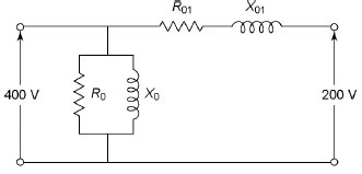
Figure E1.1
Example 1.9 A sigle-phase 4 kVA, 460/230 V, 50 Hz transformer has the following constants:
Resistance primary: 0.4 Ω; secondary 0.10 Ω
Leakage reactance primary: 0.5 Ω; secondary 0.12 Ω
Resistance and reactance of excitation circuit referred to as primary are R0 = 650 Ω and X0 = 250 Ω
Calculate readings of the instruments when the transformer is connected for:
- OC test.
- SC test.
In both tests, supply is given to high-voltage side.
Solution
R1=0.4Ω, X1 =0.5 Ω, R2 =0.1Ω, X2=0.12Ω, R0 = 650Ω, X0 = 250Ω
- OC test:
V1 = 460 V (rated voltage is applied to high-voltage side)

∴ W0=V0 I0cosθ0=VIw [∴ IW=I0 cosθ0]
= 460 × 0.707 = 325.22 W.
∴
The instrument readings are: 460 V, 1.97 A, 325.22 W.
- SC test:
R01=R1+a2R2=0.4+22×0.1=0.8Ω
X01=X1+a2X2=0.5+22×0.12=0.98Ω
∴ ![]()
Full-load current in high-voltage winding (I1) =![]()
VSC=ISC Z01=8.7×1.265=11V
PSC=ISC2 R01=(8.7)2×0.8=60.55W
Instrument readings are: 11 V, 8.7 A, 60.55 W.
1.26 SEPARATION OF CORE (OR IRON) LOSSES IN A TRANSFORMER
Hysteresis loss and eddy current loss are the components of the iron losses. For the applied fl ux density Bmax to the core, we have
Hysteresis loss = Af
and Eddy current loss = Bf2
The no load loss can be expressed as
where A and B are constants.
Figure 1.38 shows the graph, which is a straight line when ![]() and f are plotted along the y-axis and x-axis, respectively. The intercept on the y-axis gives the value of A, whereas the slope of the line gives the value of B. Now the hysteresis and eddy current loss can be determined at any desired frequency.
and f are plotted along the y-axis and x-axis, respectively. The intercept on the y-axis gives the value of A, whereas the slope of the line gives the value of B. Now the hysteresis and eddy current loss can be determined at any desired frequency.
The experimental circuit arrangement for determining ![]() and f is shown in Figure 1.39.
and f is shown in Figure 1.39.
In Figure 1.39, a variable frequency alternator supplies to the transformer under the test, which is driven by DC shunt motor whose speed can be varied over a wide range. The switches S1 and S2 are opened and the alternator is started with the help of the DC shunt motor. The speed is adjusted to the

Figure 1.38 Plot of ![]() and f
and f
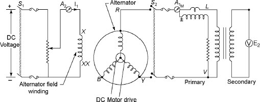
Figure 1.39 Experimental Circuit for Determining ![]() and f
and f
value of the required frequency. The excitation of the field coil (X-XX) is varied until the voltmeter on the secondary side of the transformer achieves the rated value. If E2 is the transformer emf on the secondary, we have
E2=4.44ΦmfN
For constant ![]() , the flux density in the transformer remains constant. To achieve this, the frequency of the alternator emf is varied so that
, the flux density in the transformer remains constant. To achieve this, the frequency of the alternator emf is varied so that ![]() remains constant. The necessary f can be adjusted to vary E2 so that
remains constant. The necessary f can be adjusted to vary E2 so that ![]() is kept constant. For different values of frequencies above and below the rated value, the reading of wattmeter (W) is noted. The graph
is kept constant. For different values of frequencies above and below the rated value, the reading of wattmeter (W) is noted. The graph ![]() and f is drawn to get the constants A and B. After getting the value of A and B, the hysteresis loss and eddy current loss is obtained.
and f is drawn to get the constants A and B. After getting the value of A and B, the hysteresis loss and eddy current loss is obtained.
Example 1.10 The hysteresis and eddy current loss of a transformer are 300 W and 250 W, respec-tively, if the supply voltage is 500 V at 50 Hz. Find the hysteresis loss and eddy current loss if the supply voltage is 1,000 V, 100 Hz.
Solution
Hysteresis loss at 500 V, 50 Hz = 300 W
Eddy current loss at 500 V, 50 Hz = 250 W
Induced emf (E) = 4.44 f < N = 4.44 fBmArN
E ∞ Bm f
∴ Bm ∞ ![]()
∴ Bm=α![]() [α is the constant
[α is the constant
For the first case: B < m1 = 10 α
For the second case: Bm2 = 10 α
∴ Bm1 = Bm2
Hence, Ph = Cf and Pe = Df2
∴ ![]()
When f = 50 Hz, Ph = 300 W and Pe = 250 W
∴ ![]()
When f = 100 Hz
Ph = Cf = 6 × 100 = 600W
and ![]()
1.27 TOTAL APPROXIMATE VOLTAGE DROP OF A TRANSFORMER
During no-load condition, induced voltages at the primary and secondary windings are equal to the applied voltage and secondary terminal voltage respectively. If 0V2 be the secondary terminal voltage at no load, we can write E2 = 0V2. Let V2 be the secondary voltage on load. Figure 1.40 shows the phasor diagram of a transformer referred to as secondary.
In Figure 1.40, R02 and X02 are the equivalent resistance and reactance of the transformer, respec-tively, referred to as secondary side. With O as centre, an arc is drawn in Figure 1.40, which intersects the extended OA at H. From C, a perpendicular is drawn on OH, which intersects it at G. Now AC = AH represents the actual drop and AG represents the approximate voltage drop. BF is drawn perpendicular to OH. BE is drawn parallel to AG, which is equal to FG.
The approximate voltage drop
= AG = AF+ FG = AF+ BE
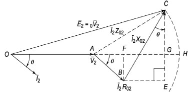
Figure 1.40 Phasor Diagram of a Transformer Referred to as Secondary
This approximate voltage drop shown in Equation (1.39) is for lagging power factor only.
For leading power factor, the approximate voltage drop will be
where ‘+’ sign is for lagging power factor and ‘-’ sign is for leading power factor.
The above calculation is referred to as secondary. It may be noted that voltage drop referred to as primary is
I1R01cosθ±I1X01sinθ (1.41)
∴% voltage drop in secondary is=![]()
![]()
where ![]()
and ![]()
1.28 EXACT VOLTAGE DROP
In Figure 1.40, the exact voltage drop is AH instead of AG. During calculation of approximate voltage drop, AG has already been calculated. If GH is being added to AG, the exact voltage drop can be obtained.
Consider the right-angled triangle OCG. We have
OC2 = OG2 + GC2
i.e. OC2 – OG2 = GC2
i.e. (OC – OG)(OC + OG) = GC2
i.e. (OH –OG)(OC + OG) = GC2
i.e. GH.2.OC= GC2 [Taking OC ≍ OG]
i.e. 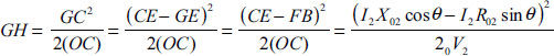
For lagging power factor, the exact voltage drop is
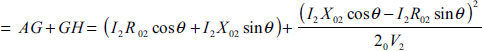
For leading power factor, the exact voltage drop is given by
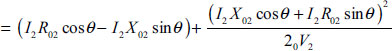
In general, the voltage drop is

and percentage voltage drop is
It may be noted that the upper sign is to be used for lagging power factor and the lower sign for leading power factor.
Example 1.11 The OC and SC tests on a 300/600 V, 50 Hz, single-phase transformer gave the fol-lowing results:
OC test (LV side): 300 V, 0.8 A, 70 W
SC test (HV side): 20 V, 12 A, 90 W
where LV and HV is low voltage and high voltage, respectively.
Find the equivalent circuit of the transformer referred to as LV side and also calculate the secondary voltage when delivering 6 kW at 0.8 p.f. (power factor) lagging.
Solution
OC test (LVside):
Instruments are placed on LV side and HV side is kept open.
V1 = 300 V, I0 = 0.8 A, W0 = 70 W
Now, ![]()
∴ IW= I0cosθ0=0.8×0.292=0.2336A
and Iμ=I0sinθ0=0.8×0.956=0.7648A
∴ ![]()
SC test:
Instruments are placed on HV side and LV side is kept open.
![]()
VSC = 20 V, ISC = 12 A, PSC = 90 W
![]()
Figure E1.2
∴ ![]()
∴ ![]()
∴ ![]()
∴ ![]()
The equivalent circuit referred to as LV side is shown in Figure E1.2.
∴ ![]()
Approximate voltage drop referred to as secondary for 0.8 power factor lagging is
=I2(R02cosθ+X02sinθ
=12.5×(0.625×0.8+1.548×0.6)=17.86 V
∴ Secondary terminal voltage = 600 – 17.86 = 582.14 V (approx.)
Example 1.12 A single-phase 200/400 V, 6 kVA, 50 Hz transformer gives the following test results:
OC test (LV side): 200, 0.8 A, 80 W
SC test (HV side): 25 V, 10 A, 90 W
where LV and HV are low voltage and high voltage, respectively.
Determine the following: (i) The circuit constants referred to as LV side and (ii) the applied voltage and efficiency if the output current is 12 A at the terminal voltage 400 V at 0.8 power factor lagging.
Solution
(i) Turns ratio (a) = ![]()
OC test:
Instrument placed on LV side
V1=200V, I0=0.8A, W0=80W
∴ ![]()
sinθ0 = 0.866
and Iμ=I0sinθ0=0.8×=0.6928 A
∴ ![]()
SC test:
Instruments placed on HV side
VSC = 25V, ISC=10A, PSC=90W
![]()

∴ The circuit parameters referred to as LV side are
R0=500Ω and X0=288.68Ω, R01=0.255Ω, X01=0.5825Ω
To maintain the output voltage at 400 V, the applied voltage can be calculated from Figure E1.3.
(V1′)2 = (V1cosθ1+I1R01)2+(V1sinθ1+I1X01)2
= (200× 0.8+ 24× 0.255)2 + (200× 0.6+ 24 × 0.5825)2
= 45,546.50
i.e. V1′ = 213.4 V

Figure E1.3
To maintain the output voltage at 400 V for the given load, the applied voltage becomes 213.4 V
From OC test: iron loss = 80 W
From SC test: copper loss = 90 W for 10 A current on the HV side.
Full-load copper loss=![]()
Total loss of the transformer = 129.6 + 80 = 209.6 W
∴ Efficiency of the transformer =![]()
1.29 PER UNIT RESISTANCE, LEAKAGE REACTANCE AND IMPEDANCE VOLTAGE DROP
Full-load voltage of a transformer can be expressed as a fraction of the full-load terminal voltage.
Let I1fl be the full-load primary current, I2fl be the full-load secondary current, V1 be the rated pri-mary voltage and V2 be the rated secondary voltage.
Per unit resistance drop of a transformer
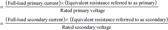
![]()
∴ ![]()
Per unit reactance drop of a transformer
Per unit reactance drop of a transformer is called per unit reactance and it is given by
Per unit impedance drop of a transformer is called per unit impedance and it is given by
1.30 VOLTAGE REGULATION OF TRANSFORMER
With constant voltage applied in primary, the secondary terminal voltage will decrease due to voltage drop across its internal resistance and leakage reactance.
Let 0V2 and V2 be the secondary terminal voltages at no load and on load respectively. There are three kinds of voltage regulation, which are discussed below.
1.30.1 Inherent Voltage Regulation
The difference 0V2 – V2 is known as inherent voltage regulation of the transformer.
1.30.2 Voltage Regulation Down
If inherent voltage drop is divided by 0V2, it is known as voltage regulation down. Mathematically, we can write
1.30.3 Voltage Regulation Up
If inherent voltage drop is divided by V2, it is known as voltage regulation up. Mathematically, we can write it as
The secondary terminal voltage not only depends on load current but also on the power factor of the load. The regulation is said to be at full load provided V2 is determined for full load and at specified power factor condition. V2 drops more and more with increasing load current. For lagging power factor load, V2 < E2, the voltage regulation is positive. For leading power factor load, V2 > E2, the voltage regulation is negative.
To maintain constant secondary terminal voltage on load, the primary terminal voltage is adjusted. It is expected that voltage drop would be as small as possible. Therefore, the lesser the value of regula-tion, the better is the performance of a transformer.
1.31 CALCULATION FOR VOLTAGE REGULATION
The voltage regulation up is expressed mathematically by
Positive sign is for lagging power factor and negative sign is for leading power factor.
1.31.1 Zero Voltage Regulation
For lagging power factor and unity power factor, 0V2 > V2. Therefore, we get positive voltage regulation. For leading power factor, V2 starts increasing. At a certain leading power factor, 0V2 = V2 and hence regulation becomes zero. If the load power factor is further increased, 0V2 becomes less than V2 and hence regulation becomes negative. For zero voltage regulation, we have
0V2 – V2 = 0
i.e., I2(R02cosθ–X02sinθ)=0
![]()
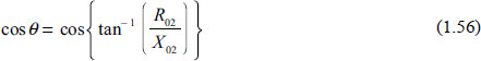
Equation (1.56) shows the leading power factor at which voltage regulation becomes zero.
1.31.2 Condition for Maximum Voltage Regulation
Maximum voltage regulation can be obtained for lagging power factor. For maximum voltage regula-tion, we have

i.e., –R02sinθ+X02cosθ=0
i.e., ![]()
This is satisfied only when the power factor of the load is lagging. The regulation is maximum when the load power factor angle is equal to the impedance angle of the transformer.
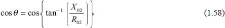
Equation (1.58) shows the power factor of the load at which voltage regulation is maximum.
Figure 1.41 shows the variation of regulation with the power factor of the load. Figure 1.41 also shows that regulation becomes maximum when the power factor of the load is lagging and it becomes zero when the power factor is leading.
Example 1.13 A 6 kVA, 500/250 V, 50 Hz, single-phase transformer has the following test results:
OC test (LV side): 250V, 1.5A, 80W
SC test (HV side): 22V, 10A, 90W
Determine the following:
- The approximate equivalent circuit referred to as HV side.
- Voltage regulation and efficiency at full load and 0.8 power factor lagging load.
- The efficiency of the transformer at half of full load and 0.8 power factor lagging load.
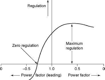
Figure 1.41 Effect of Load Power Factor on Regulation
Solution
(i) Turns ratio (a)=![]()
OC test:
(I0)lv = 1.5A
i.e., 
i.e., ![]()
Instruments readings when they are placed on HV side
V1 = 500, I0 = 0.75 A and W0 = 80 W
∴ ![]()
∴ IW = I0 cosθ0 = 0.75 × 0.214 = 0.1605 A
and ![]()
∴ ![]()
referred to as HV side.
Instruments placed on HV side.
VSC = 22 V, ISC = 10 A, PSC = 90 W
∴ ![]()
and ![]()
The equivalent circuit is shown in Figure E1.4.
Figure E1.4
(ii) Full-load secondary current of the transformer
![]()
∴ Approximate voltage drop of the transformer referred to as secondary
ΔV=I2(R02cosθ+X02sinθ)
Now ![]()
Here cosθ = 0.8 (lagging)
∴ sinθ = 0.6
∴ ΔV = 24×(0.225×0.8+0.5×0.6) = 11.52 V
∴Regulation of the transformer=![]() =0.046 p.u=4.6%
=0.046 p.u=4.6%
From OC test: iron loss of the transformer = 80 W
From SC test: copper loss of the transformer = 90 W when primary current is 10 A, that is, secondary current is 20 A.
Full-load copper loss of the transformer=![]()
∴ Total losses of the transformer at full load = 80 + 129.6 = 209.6 W
∴ Output of the transformer at full load and 0.8 p.f. lagging = V2I2 cos θ2
Secondary terminal voltage (V2) = 250 – Approximate voltage drop = 250 – 11.52 = 238.48 V
∴ Output power = 238.48×24×0.8 = 4,578.816 W
∴ Efficiency of the transformer
![]()
Another method to calculate the efficiency
Output power = 6 ×103 × 0.8 = 4,800 W
∴ Efficiency of the transformer
![]()
This method gives an approximate answer. If equivalent resistance and reactance are available, it is sug-gested that the previous method should be used. Otherwise, the approximate method may be used.
(iii) Copper loss of the transformer at half of full load =![]()
Voltage drop at half-load =![]() =5.76 V2′=250–5.76=24424V
=5.76 V2′=250–5.76=24424V
∴ Output=![]() ×244.24×24×0.8 = 2,344.704 W
×244.24×24×0.8 = 2,344.704 W
∴Effi ciency of the transformer
![]()
Example 1.14 A12kVA, 1,000/100 V, 50Hz, single-phase transformer has the following test results:
OC test (LV side): 100V, 0.7A, 85W
SC test (HV side): 60V, 10A, 95W
Determine the following:
- Core loss of the transformer.
- Equivalent resistance and leakage reactance referred to as HV side.
- Equivalent resistance and leakage reactance referred to as LV side.
- Regulation of the transformer at full load and half load at 0.8 power factor lagging.
- Transformer terminal voltage at full load at 0.8 power factor lagging.
- Efficiency of the transformer at full load and half load at 0.8 power factor lagging.
Solution
![]()
- Core loss or iron loss of the transformer = 85 W
- From SC test
VSC = 60V, ISC = 10A, PSC = 95W
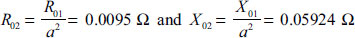
∴

∴

∴Resistance and leakage reactance referred to as HV side are 0.095 Ω and 5.924 Ω, respectively.
-
-

∴ Approximate voltage drop= I2(R02cosθ+X02sinθ)
= 120×(0.0095× 0.8+ 0.05924× 0.6) = 5.177 V
Regulation of the transformer=
- At full-load transformer terminal voltage = 100 – 5.177 = 94.823 V
- Output = 94.823 × 120 × 0.8 = 9,103 W
∴ Copper loss at full load =
∴ Total loss of the transformer = 85 + 136.8 = 221.8 W

At half load,
At half load, approximate voltage drop of the transformer
= 60×(0.0095×0.8+0.05924×0.6)=2.588 V
V1=(100–2.588)V=97.412 V
Output power = 97.412 × 60 × 0.8 = 4,675.776 W
Copper loss at half-load=
∴ Total losses = 85 + 34.2 = 119.2 W
∴ Efficiency of the transformer at half-load =
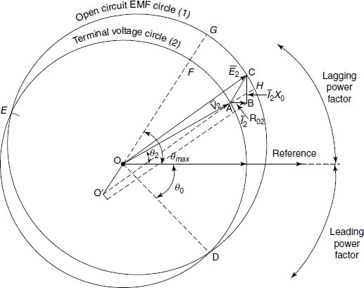
Figure 1.42 Kapp’s Diagram
1.31.3 Kapp’s Regulation
Kapp had designed a diagram shown in Figure 1.42 to determine the regulation at any power factor. The description of the construction of the diagram is shown below.
Load current (I2) is taken as a reference phasor. OA representing V2 is drawn at angle θ2 with I2. AB represents I2R02 drawn parallel to I2, whereas BC represents I2X02 drawn perpendicular to AB, i.e., I2. Here OC represents secondary emf (0V2 = E2) at no-load. The circle 1 known as often circuit EMF circle is drawn with O as centre and OC as radius. The line OO′ is drawn parallel to AC representing I2Z02. With O′ as centre and OA as radius, the circle 2 known as terminal voltage circle is drawn, which intersects with circle 1 at the points D and E. The region above and below the reference line represents the lagging and leading power factors region, respectively. The point D is the point corresponding to zero regulation. The intercept FG gives the maximum regulation, which is drawn through O and drawn parallel to AC. The regulation at any power factor angle θ is obtained by extending OA to meet the outer circle at H. The regulation at the required power factor cosθ is represented by AH, which is the intercept between the two circles.
1.32 LOSSES IN A TRANSFORMER
Two types of losses occur in a transformer:
- Core loss or iron loss occurs in a transformer because it is subjected to an alternating flux.
- The windings carry current due to loading and hence copper losses occur.
1.32.1 Core or Iron Loss
The separation of core losses has already been introduced. The alternating flux gets set up in the core and it undergoes a cycle of magnetization and demagnetization. Therefore, loss of energy occurs in this process due to hysteresis. This loss is called hysteresis loss (Ph), which is expressed by
where Kh is the hysteresis constant depending on the material, Bm is the maximum flux density, f is the frequency and V is the volume of the core.
The induced emf in the core sets up eddy current in the core, and hence eddy current loss (Pe) occurs, which is given by
Pe=KeBm2f2t2 W per model W (1.60)
where Ke is the eddy current constant and t is the thickness of the core.
Since the supply voltage V1 at rated frequency f is always constant, the flux in the core is almost constant. Therefore, flux density in the core remains constant. Hence, hysteresis and eddy current losses are constant at all loads. Thus, the core loss or iron loss is also known as constant loss. The iron loss is denoted by Pi.
Iron loss is reduced using high-grade core material such as silicon steel having very low hysteresis loop for reducing hysteresis loss and laminated core for reducing the eddy current loss.
1.32.2 Copper Loss
The loss of power in the form I2R due to the resistances of the primary and secondary windings is known as copper losses. The copper loss also depends on the magnitude of currents flowing through the windings. The total Cu loss is given by
Copper losses are determined on the basis of R01 or R02 which is determined from short circuit test. Since the standard operating temperature of electrical machine is taken as 75 °C, it is then corrected to 75 °C.
The copper loss due to full-load current is known as full-load Cu loss. If the load on the transformer is half, the Cu loss is known as half-load Cu loss, which is less than the full-load Cu loss. The Cu loss is also known as variable loss.
There are two other losses known as stray loss and dielectric loss. Since leakage field is present in a transformer, eddy currents are induced in the conductors, tanks walls and bolts etc. Stray losses occur due to this eddy currents. Dielectric loss occurs in insulating materials coil and solid insulation. These two losses are small and hence neglected.
Therefore, the total loss of the transformer = Iron loss + Cu loss = Pi + PCu
1.33 EFFICIENCY OF A TRANSFORMER
Due to the losses in a transformer, its output power is less than the input power.
∴ Power output = Power input – Total losses
∴ Power input = Power output + Total losses = Power output + Pi + PCu
The ratio of power output to power input of any device is called its efficiency (η).
Output power of a transformer at full-load = V2I2ftcosθ, where cosθ is the power factor of the load, I2ft is the secondary current at full load and V2 is the rated secondary voltage of the transformer.
Full-load copper loss of the transformer = I2ftR02.
∴ Efficiency of the transformer at full load is given by
Now V2I2ft = VA rating of the transformer.
∴ 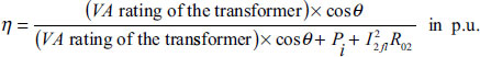
Efficiency of the transformer at any load m is given by
where m=![]() and PCuft is the Cu loss of the transformer at full load.
and PCuft is the Cu loss of the transformer at full load.
1.34 CONDITION FOR MAXIMUM EFFICIENCY
During working of a transformer at constant voltage and frequency, its efficiency varies with the load. Its efficiency increases as the load increases. At a certain load, its efficiency becomes maximum. If the transformer is further loaded, its efficiency starts decreasing. Figure 1.43 shows the plot of efficiency versus load current.
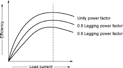
Figure 1.43 Comparison Efficiency and Current
To determine the condition of maximum efficiency, let us assume that the power factor of the load remains constant and the secondary terminal voltage (V2) is constant. Therefore, efficiency becomes only a function of load current (I2).
For maximum efficiency
![]()
Now, ![]()
∴ 
i.e., 
i.e., V2I2cosθ+Pi+I22R02–V2I2cosθ–2I22R02=0
To achieve maximum efficiency, Iron loss = Cu loss
i.e., Constant loss = Variable loss
1.34.1 Load Current at Maximum Efficiency
Let I2M be the load current at maximum efficiency.
∴ I2M2R02=Pi
i.e., ![]()
Let I2ft be the full-load current.
i.e., 
Equation (1.67) shows the load current in terms of full-load current at maximum efficiency.
1.34.2 kVA Supplied at Maximum Efficiency
For constant V2 the kVA supplied is the function of load current only.
∴ 

Example 1.15 A single-phase 10 kVA, 2,000/200 V, 50 Hz transformer has the following test results:
OC test (LV side): 200V, 0.8A, 60W
SC test (HV side): 40V, 4A, 70W
Calculate the following:
- The efficiency of the transformer at half load and 0.8 power factor lagging.
- The load kVA at which maximum efficiency occurs and also the maximum efficiency at 0.8 power factor lagging.
- The voltage regulation at 0.8 power factor leading on full-load condition.
Solution
From OC test, iron loss of the transformer = 60 W
Full load primary current (I1) =![]()
From SC test
![]()
and ![]()
Again, ![]()
∴ Approximate voltage drop at secondary
ΔV=I2(R02cosθ+X02sinθ)
∴ Secondary side current (I2) at half-load =![]()
∴ ΔV = 25×(0.04375×0.8+0.0899×0.6) = 2.2235 V
∴ V2′=200–2.2235=197.7765V
∴ Output power = 197.7765×25×0.8= 3,955.53 W at full-load.
∴ Copper loss at half-load=
∴ Efficiency of the transformer at half-load=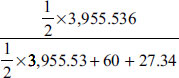
= 0.9577 p.u.=95.77%
(ii) At maximum efficiency, Cu loss = Iron loss = 60 W
∴ I12R01 = 60, where I1 is the primary current at maximum efficiency
![]()
∴ I1=3.703A
Here V2 is not constant.
∴ Approximate voltage drop at secondary
ΔV = I2(R02cosθ+ X02sinθ)
∴ ΔV = 3.703X (4.375X 0.8+ 8.99x 0.6) = 32.934 V
∴ V1′ = V1 – ΔV = 2,000– 32.934 = 1,967.066 V
∴ Load kVA at maximum efficiency = 1,967.066 × 3.703 VA = 7.284 kVA
∴ Output = 7.284 × 103 × 0.8 = 5,827.2 W
![]()
(iii) Voltage regulation at 0.8 p.f. leading on full-load condition:
I2 = 50 A at full load.
∴ ΔV = I2 (R02 cosθ–X02 sinθ)
= 50 × (0.04375 × 0.8 – 0.0899 × 0.6) = –0.947 V
∴ Regulation of the transformer=![]()
1.35 ALL-DAY EFFICIENCY
The ratio of output in watts to input in watts is called commercial efficiency of a transformer. Distribution transformers are used for supplying lighting and general networks. Distribution transformers are energized throughout the day. Their secondaries are at no load most of the time in a day except during the hours of lighting period. Core loss occurs throughout the day. Copper loss occurs only when they are loaded and hence is less important. To judge their performance, all-day efficiency or operational efficiency is calculated. The all-day efficiency is defined by
The all-day efficiency is less than the commercial efficiency of a transformer.
Example 1.16 A 200 kVA single-phase transformer is in circuit throughout 24 hours. For 8 hours in a day, the load is 150 kW at 0.8 power factor lagging and for 7 hours, the load is 90 kW at 0.9 power factor. Remaining time or the rest period, it is at no-load condition. Full-load Cu loss is 4 kW and the iron loss is 1.8 kW. Calculate the all-day efficiency of the transformer.
Solution
Full-load output = 200 kVA, Full-load Cu loss = 4 kW, Iron loss = 1.8 kW.
1.36 POLARITY TEST OF A SINGLE-PHASE TRANSFORMER
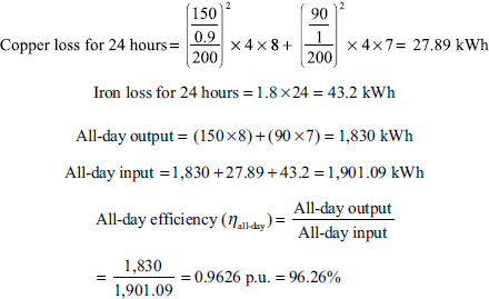
Polarity testing of transformers is vital before connecting them in parallel. Otherwise, with incorrect polarity, it is not possible to connect them in parallel. The rated voltage is applied to the primary and its two terminals are marked as A1 and A2, respectively, as shown in Figures 1.44(a) and 1.45(b), respectively. The secondary winding terminals are also marked as a1 and a2, shown in Figures 1.44(a) and 1.45(b), respectively. Now a voltmeter is connected across A2 and a2. if it measures the difference of E1 and E2, A2 and a2 are of the same polarity. If it measures the addition of E1 and E2, A2 and a2 are of opposite polarity.
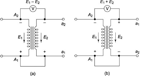
Figure 1.44 Polarity Test of a single-phase Two Winding Transformer
1.37 SUMPNER’S TEST
To determine the rise of maximum temperature of a transformer, its load test is of utmost importance. Using suitable load impedance, small transformers can be put on full load. The full-load test of large transformers is not possible because considerable wastage of energy occurs and it is difficult to get a suitable load for absorbing full-load power. Sumpner’s test is used to put large transformer on full load. This test can also be used to determine the efficiency of a transformer. Figure 1.45 shows the schematic diagram of Sumpner’s test. This test is also known as back to back test or load test.
This test requires two identical transformers. The two primaries are connected in parallel and are energized at rated voltage and rated frequency. The wattmeter W1 records the reading of core loss of both the transformers. Next the two secondaries are connected in series in such a way that their polarities are in phase opposition and the reading of the voltmeter V2 becomes zero. With the help of voltage regulator fed from source, a voltage is injected to the secondary of the transformers, which is adjusted until the rated secondary current flows. The voltmeter reads a voltage, which is the leakage impedance drop of the two transformers. The reading of W1 remains unaltered. The wattmeter W2 reads the total copper (Cu) loss of the two transformers. Although the transformers are not supplying any load current, this test measures the full iron loss as well as copper loss of the transformers. The net input during this test is W1 + W2. To measure the temperature rise, the two transformers are kept under rated loss conditions for several hours.
Figure 1.45 Sumpner’s Test
1.38 PARALLEL OPERATION OF SINGLE-PHASE TRANSFORMER
It is required to connect a second transformer in parallel with the first transformer if the load exceeds the rating of the transformer shown in Figure 1.46. The primary windings are connected to the supply bus bars while the secondary windings are connected to the load bus bars. During paralleling of the transformer, similar polarities of the transformers should be connected to the same bus bars shown in Figure 1.46. Otherwise, the two emfs induced in the secondary windings with incorrect polarities will produce the equivalent of a dead short circuit shown in Figure 1.47.
The following conditions are important for parallel opera-tion of transformers:
- The voltage ratings of both the primary and the secondary of the transformers should be identical. Small differences are permissible if the resultant circulating currents can be tolerated.
- The connections of the transformers should be proper with respect to their polarities.
- The percentage impedances should be equal in magnitude and the X/R ratio must be the same to avoid circulating current and operation at different power factors.
- The equivalent impedances must be inversely proportional to the respective kVA ratings.
The above conditions must be satisfied by paralleling transformers of identical ratings of the same make/model. With different kVA ratings of even the same make/model, the effects in steps 1, 2 and 3 may appear in undesirable amounts. Step 2 must be carried out satisfactorily even if steps 1, 3 and 4 are slightly modified.
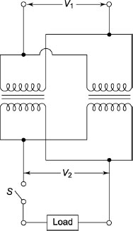
Figure 1.46 Parallel Operation of Transformers
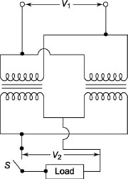
Figure 1.47 Parallel Operation of Transformers with Incorrect Polarities
1.39 LOAD SHARING BY TWO TRANSFORMERS
Let us consider the following two cases:
- Equal voltage ratios.
- Unequal voltage ratios.
1.39.1 Equal Voltage Ratios
Assume no-load voltages EA and EB are identical and in phase. Under these conditions if the primary and secondary are connected in parallel, there will be no circulating current between them on no load.
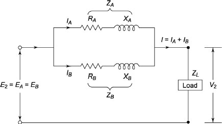
Figure 1.48 Equal Voltage Ratios
Figure 1.48 shows two impedances in parallel. Let RA, XA and ZA be the total equivalent resistance, reactance and impedance of transformer A and RB, XB and ZB be the total equivalent resistance, reactance and impedance of transformer B.
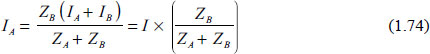
From Figure 1.48, we have
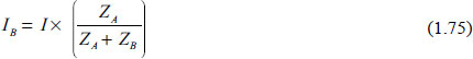
∴ ![]()
Equation (1.73) suggests that if two transformers with different kVA ratings are connected in parallel, the total load will be divided in proportion to their kVA ratings if their equivalent impedances are inversely proportional to their respective ratings.
Since ![]()
i.e., ![]()
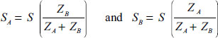
Similarly, load shared by transformer A,
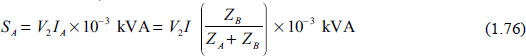
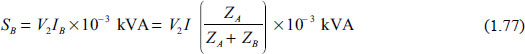
Total S=SA+SB=V2I×10-3 kVA
∴ 
Example 1.17 Two single-phase transformers A and B of equal voltage ratio are running in parallel and supply a load of 800 A at 0.8 power factor lagging having equivalent impedances (1.5 + j3) Ω and (2 + j 4.5) Ω respectively. Find the current supplied by each transformer and the ratio of the kW output of the two transformers.
Solution
ZA=(1.5+j3)Ω and ZB=(2+j4.5)Ω
![]()
∴ IA=(1.47+j0.067)IB
Let us take the secondary terminal voltage as reference.
I=800(0.8–j0.6)=(640–j480)A
Again, I=IA+IB=(1.47+0.067)IB+IB=(2.47+j0.067)IB
![]()
IA=(1.47+j0.067)IB=(1.47+j0.067)×(253.65–j201.2)=386.34–j287.77
= 481.74∠–36.68°A
The ratio of kW outputs is equal to the ratio of in-phase components of the two currents.
![]()
Example 1.18 Two transformers A and B are connected in parallel and supply 400 V Both transformers have no-load ratio of 800/400 V. Transformer A is rated at 100 kVA, its total resistance and reactance being 2 per cent and 3 per cent, respectively. The rating of transformer B is 150 kVA, its total resistance and reactance being 1 per cent and 4 per cent, respectively. Determine the load on each transformer and secondary voltage for a load of 250 kVA at 0.8 power factor lagging.
Solution
![]()
S=250(0.8–j0.6) = 200–j150
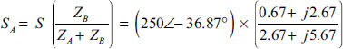
= (250∠–36.87°)×(0.439∠11.12°)=109.75∠–25.75°
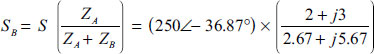
=(250∠–36.87°)×(0.575∠–8.47°)=143.75∠–45.35°
Since ZA and ZB are in parallel
![]()
Percentage drop over ![]()
![]()
1.39.2 Unequal Voltage Ratios
For unequal voltage turns ratio, if the primary is connected to the supply, a circulating current will flow in the primary even at no load. The circulating current will be superimposed on the currents drawn by the load when the transformers share a load.
Let V1 be the primary supply voltage, a1 be the turns ratio of transformer A, a2 be the turns ratio of transformer B, ZA be the equivalent impedance of transformer A (= RA + jXA) referred to as secondary, ZB be the equivalent impedance of transformer B (= RB + jXB) referred to as secondary, IA be the output current of transformer A and IB be the output current of transformer B.
The induced emf in the secondary of transformer A is
The induced emf in the secondary of transformer B is
Again, V2 = IZL where ZL is the impedance of the load
From Equations (1.78), (1.79) and (1.80), we have
∴ EA − EB = IAZA − IBZB
Substituting IA from Equation (1.83) in Equation (1.82), we have
![]()
i.e., ![]()
Example 1.19 Two transformers A and B are connected in parallel and supply a common load. Open circuit emf of A and B are 5,500 V and 5,400 V, respectively. Equivalent impedance in terms of secondary of A and B are (0.4 + j4) Ω and (0.1 + j 1.5) Ω respectively. The load impedance is (10 + j 6) Ω. Find the current supplied by each transformer.
Solution
![]()
![]()
![]()
Similarly,
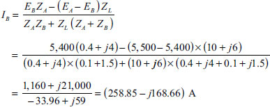
1.40 AUTOTRANSFORMERS
Two-winding transformers have already been discussed. In such transformers, the two windings are electrically isolated and emf is induced in the secondary winding due to mutual induction. There also exists other types of transformers in which a part of the winding is common to both the primary and secondary circuits. These transformers are termed as autotransformers. In an autotransformer, the two windings are electrically connected and it works on the principle of induction and conduction.
1.40.1 Construction
Figure 1.49 depicts an autotransformer in which only one winding is wound on a laminated magnetic core. It also shows that a single winding is used as primary and secondary and a part of the winding is common to both the primary and secondary. The autotransformers are also classified as step-up and step-down transformers because voltage can be stepped up and stepped down using these transformers.
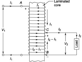
Figure 1.49 Step-down Autotransformer
Figure 1.50(a) shows a two-winding trans-former. Figure 1.50(b) shows an autotransformer, which steps down the voltage. In a step-up auto-transformer, the entire winding is used as a primary
winding and the part of the winding is used as a secondary winding. Figure 1.50(c) shows an autotrans-former, which steps up the voltage. The entire winding is used as a secondary winding.
From Figures 1.50(a) and 1.51(b), it seems that an autotransformer is similar to a resistance potential divider. An autotransformer can step up and step down the voltage. An autotransformer has less loss whereas more loss occurs in a potential divider. Therefore, the efficiency of an autotransformer is higher than that of a potential divider. In a potential divider, input current is more than the output current. In an autotransformer, if output voltage is less than the input voltage, the output current will be higher than the input current.
Let I1 be the input current, I2 be the output current, V1 be the input voltage, V2 be the output voltage, cosθ1 be the input power factor and cosθ2 be the output power factor.
If we neglect the losses
If we neglect the internal impedance drops and losses, Equation (1.86) can be written as follows
V1I1=V2I2
where N1 is the total number of turns in the primary and N2 the total number of turns in the secondary.
Figure 1.51 shows a step-down autotransformer. Let the point X be positive with respect to Z. At no load the exciting current flows from X to Z and it produces a working mmf vectorially downwards, i.e., from X to Z. During the presence of load at the secondary, the current flows from Z to Y and it weakens the produced working magnetomotive force (mmf), and the transformer draws extra current from primary. Ultimately, it will maintain the same working mmf. In winding XZ, the current is I1 (from X to Y) whereas in winding YZ the current is I2 (from Z to Y). V2 < V1, I2 > I1 and the net current through YZ is I2 – I1 (from Z to Y).
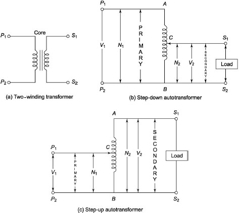
Figure 1.50 Two-winding and Autotransformers
∴ mmf of winding

Figure 1.51 Step-down Autotransformer

∴ Voltamperes across winding XY are transferred by transformer action to load connected across winding YZ.
∴ ![]()
Total input VA is V1I1 and (V1 – V2) I1 is transformed to the load by transformer action and the remaining VA is conducted directly.
Conducted VA = Total Input VA– Transformed VA = V1I1– (V1– V2)I1 = V2I1
1.40.2 Copper Saving in Autotransformer
We know that for any winding, the total length of winding is proportional to the number of turns (N), while its cross-section is proportional to the current (I). Therefore, its copper weight is proportional to the product of N and I.
∴ Weight of copper ∞ NI where I is the current in winding and N is the number of turns of the winding.
Figure 1.52(a) shows a two-winding transformer, whereas Figure 1.52(b) shows a step-down auto-transformer.
Let WTW and WAT be the total weight of copper in the two-winding transformer and in the autotransformer. In Figure 1.52(a), let N1 and N2 be the number of turns of primary and secondary windings, respectively. In Figure 1.52(b), let N1 and N2 be the number of turns of primary winding and secondary winding, respectively.
In two-winding transformer, weight of copper of primary ∝ N1I1 and that of secondary ∝ N2I2
In autotransformer, weight of copper of section XY ∝ (N1 – N2)I1 and that of section YZ ∝ (I2 – I1)N2.
From Equations (1.90) and (1.91), we have
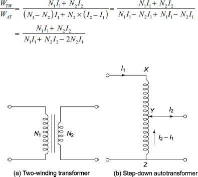
Figure 1.52 Two-winding and Step-down Autotransformer
∴ 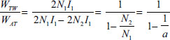
Therefore, saving of copper ![]()
Thus, saving of copper is dependent on the turns ratio ‘a’.
1.40.3 Conversion of Two-winding Transformer into Single-phase Transformer
Figure 1.53 shows a two-winding transformer having primary and secondary voltages of 1,000 V and 400 V respectively. There are two ways to convert it into an autotransformer.
Figure 1.53 Two-winding Transformer
- Additive polarity: Figure 1.54 shows an autotrans-former obtained from a two-winding transformer by additive polarity and it results in a step-up transformer.
- Subtractive polarity: Figure 1.55 shows an autotransformer obtained from a two-winding trans-former by subtractive polarity and it results in a step-down transformer.
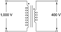

Figure 1.54 Additive Polarity
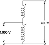
Figure 1.55 Subtractive Polarity
1.40.4 Advantages of Autotransformers
Autotransformers have the following advantages:
- Less amount of copper is required.
- Due to smaller size, cost is less compared to two-winding transformer.
- The resistance and reactance are less compared to a two-winding transformer and hence it has superior voltage regulation.
- Copper (Cu) loss is less.
- Volt-ampere rating is more compared to a two-winding transformer.
- Since loss is less, efficiency is more.
- It is possible to get smooth and continuous variation of voltage.
1.40.5 Disadvantages of Autotransformers
In spite of various advantages of autotransformers, the following are the disadvantages of autotrans-former:
- There is possibility of high short circuit currents for short circuits on the secondary side due to low impedance.
- The full primary current will appear across the secondary causing higher voltage on secondary resulting in danger of accidents if the common winding is open circuited.
- Since there is no electrical isolation between primary and secondary, risk factor appears at high voltage levels.
- It is economical only if the voltage ratio is less than 2.
1.40.6 Applications of Autotransformers
Autotransformers have the following applications:
- They are used as a starter for safely starting machines such as induction motors and synchronous motors.
- They are used as boosters to give a small boost to a distribution cable for compensating the voltage drop.
- They can be used as furnace transformers to supply power to the furnaces at the required supply voltage.
- They can be used as variac.
Example 1.20 A single-phase 2,400/240 V, 120 kVA two-winding transformer is connected as an autotransformer with additive and subtractive polarity. Determine the kVA rating of the autotransformer in both cases and also the power transformed and the power conducted. Show the current distribution in both cases. If the efficiency of the two-winding transformer is 98 per cent on full load at unity power factor, find the efficiency of the transformer on full load at unity power factor.
Solution
For the two-winding transformer
![]()
(i) Additive polarity: The current distribution is shown in Figure E1.4(a).
![]()
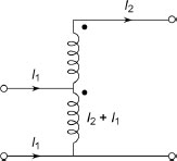
Figure E1.4(a)
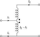
Figure E1.4(b)
![]()
Power transformed=240×500=120kVA
Power conducted=1,320–120=1,200kVA
Losses of two-winding transformer=![]()
Since autotransformer is operated at rated voltage and current, losses will remain constant.
∴ ![]()
(ii) Subtractive polarity: The current distribution is shown in Figure E1.4(b).
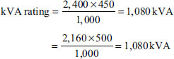
Power transformed=240×500=120 kVA
Power conducted=1,080–120=960 kVA
Since autotransformer is operated at rated voltage and current, losses will remain constant.
∴ ![]()
1.41 PULSE TRANSFORMER
Figure 1.56 shows ideal rectangular pulse input to the pulse transformer, which couples a source of pulses of electrical energy to the load. Its shape and other properties are maintained properly. The size of these transformers is small and they have few turns. The inter-winding capacitance of these transformers is low. The leakage reactance of the windings is small. Ferrites or wound strips of high permeability alloys such as permalloy are used to construct the cores. Therefore, these transformers have high magnetizing inductance. A high-voltage insulation is used between windings and to ground. Figure 1.57 shows practical rectangular input pulses to such transformers. Small pulse transformers are used in computers, pulse generators and so on, whereas large pulse transformers are used in radar systems and so on.
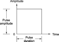
Figure 1.56 Ideal Rectangular Pulse Input
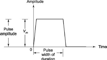
Figure 1.57 Practical Rectangular Input Pulse
1.41.1 Pulse Response Characteristics
Figure 1.57 shows the practical input signal. Since dI/dt cannot be infinite, the ideal rectangular pulse cannot be obtained. The output response is usually damped oscillation type due to the stray capacitance. Generally, leakage reactance of the pulse transformer is kept small to obtain the shortest rise time. Overshoot and back swing are present in the response, which extends below zero amplitude. This part of the response is known as trailing edge response. The response in between trailing edge and leading edge is of flat type and it is called top response. Figure 1.58 shows the overall voltage pulse shape of the pulse transformer output.
The following parameters are important to define the limits of permissible phase distortion:
- Pulse amplitude: The maximum peak value of the pulse excluding the unwanted spikes is known as pulse amplitude.
- Rise time (Tr ): Time taken by the output pulse to rise from 10 per cent of peak pulse amplitude to 90 per cent of peak pulse amplitude during its first attempt is known as rise time (Tr).
- Overshoot: The amount by which the output pulse exceeds its peak amplitude is termed as over-shoot.
- Pulse width: The time interval between the first and last instant at which the instantaneous amplitude achieves 50 per cent of the peak amplitude is known as pulse width or pulse duration.
- Droop: The displacements of the pulse amplitude during its flat response are known as droop. It is also termed as tilt.
- Fall time (Tf): The time taken by the output pulse to decrease from 90 per cent of its peak amplitude to 10 per cent of its peak amplitude during trailing edge response is known as decay time.
- Back swing: The portion of the trailing edge which extends below the zero amplitude level is known as back swing.
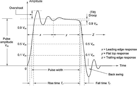
Figure 1.58 Pulse Transformer Output
1.41.2 Usage of Pulse Transformer
Pulse transformers have the following usages:
- SCR and switching transistors.
- Radar systems.
- Cathode ray tubes.
- Microwave tube circuits.
- Data-handling circuits.
- Analogue switching applications.
- Transmission line pulse transformers are useful in fast pulse signal transmission applications.
- Pulse transformers are also useful in digital signal processing.
1.42 WELDING TRANSFORMERS
Figure 1.59 shows a schematic diagram of a welding transformer having thin primary windings with a large number of turns. On the other hand, the secondary has more area of cross-section and less number of turns ensuring less voltage and very high current in the secondary. One end of the secondary is connected to the welding electrode, whereas the other end is connected to the pieces to be welded. If any high current flows, heat is produced due to the contact resistance between the electrode and the pieces to be welded. The generated heat melts a tip of the electrode and the gap between the two pieces is filled.
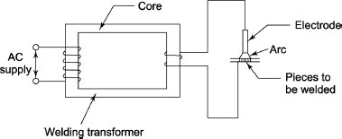
Figure 1.59 Welding Transformer
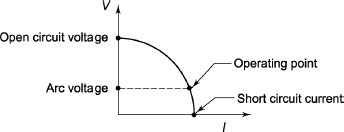
Figure 1.60 Volt-ampere Characteristic of a Welding Transformer
The winding used for the welding transformer is highly reactive. Otherwise, a separate reactor may be added in series with the secondary winding.
Figure 1.60 shows the volt-ampere characteristic of a welding transformer.
1.42.1 Reactors Used with Welding Transformers
To control the arc, various reactors are used with welding transformers. Some methods to control the arc are given below:
- Tapped reactor: With the help of taps on the reactor, the output current is regulated. This has limite number of current settings shown in Figure 1.61.
- Moving coil reactor: Figure 1.62 shows a moving coil reactor in which the reactive distance between primary and secondary is adjusted. The current becomes less if the distance between the coils is large.
Figure 1.61 Tapped Reactor
Figure 1.62 Moving Coil Reactor
- Moving shunt reactor: Figure 1.63 shows a moving shunt reactor in which the position of the central magnetic shunt can be adjusted. Change of the output current is obtained due to the adjustment of the shunted flux.
- Continuously variable reactor: Figure 1.64 shows a continuously variable reactor in which the height of the reactor is continuously varied. Greater reactance is obtained due to greater core insertion and hence the output current is less.
- Saturable reactor: Figure 1.65 shows a saturable reactor. To adjust the reactance of the reactor, the required DC excitation is obtained from a DC controlled transducer. Reactor approaches saturation if the DC excitation current is more. Therefore, changes of current are obtained due to the change of reactance.
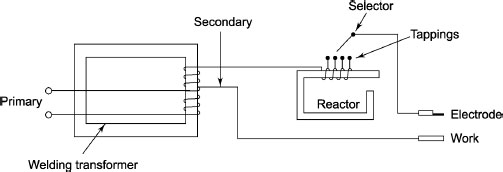
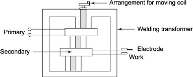

Figure 1.63 Moving Shunt Reactor
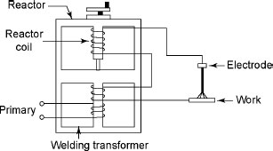
Figure 1.64 Continuously Variable Reactor
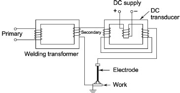
Figure 1.65 Saturable Reactor
1.43 CURRENT TRANSFORMER
Since the high alternating current should not be allowed to pass through normal ammeters and current coils of wattmeters, the current is reduced with the help of a current transformer. Current transformer is a device having two windings called primary and secondary. It transfers energy from one side to another with suitable change in level of current or voltage. It basically has a primary coil with a few turns having large cross-sectional area. This side is connected in series with the line carrying high current shown in Figure 1.66. On the other hand, the secondary is made up of many turns of fine wire having rating of 5 A current. This is connected to the coil of a low-range meter. Current transformers are basically step-up transformers, that is, stepping up the voltage and hence stepping down the current. If I1 and I2 be the currents in primary and secondary sides and N1 and N2 be the number of turns of primary and secondary windings, we can write
![]()
If the current ratio of CT and meter reading are known, the actual line current value can be determined. The secondary of CT should not be kept open. If it is kept open, secondary current will be zero and ampere turns produced by the secondary will be zero. Since the secondary ampere turns oppose the primary ampere turns, the counter mmf will be zero. Hence, unopposed primary produces heavy flux in the core, which causes excessive core losses. Hence, large emf will be induced in primary and secondary. This will damage the insulation, which is dangerous from the operating point of view.

Figure 1.66 Current Transformer
1.44 POTENTIAL TRANSFORMER
These transformers reduce the voltage and have the same basic principle as current transformers. Figure 1.67 shows a potential transformer. The primary winding of PT consists of a large number of turns and the secondary winding consists of a small number of turns. The secondary is always grounded for safety purposes.
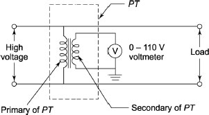
Figure 1.67 Potential Transformer
1.45 TAP CHANGING TRANSFORMERS
Electrical energy at constant voltage without interruption must be ensured by the electric supply company. The voltage at the consumer terminal should not increase the specified limit as per the specification of the country. The undesirable phenomena will happen to the equipment connected to the system when there is change in terminal voltage. This will cause the poor performance of the apparatus and life of the equipment will be reduced. The following are the examples on the performance of the equipments due to reduction in the voltage:
- Fluorescent lamp will not glow at low voltage.
- The 75 per cent of load on power system consists of induction motors. Since the output torque of induction motor is proportional to the square of the voltage, the output torque of the motor will be reduced due to the reduction of the voltage.
- Due to reduction of the supply voltage, the picture of the television set becomes smaller and smaller and rolls off.
- The illumination of power will be reduced by 75 per cent due to 6 per cent under voltage, whereas the life of the incandescent lamps will be reduced by 50 per cent due to 6 per cent over voltage.
- Due to much variation in voltage, mal-operation of detection of equipment connected to the system may occur.
The voltage at the receiving end is reduced due to the drop at the line, which is dependent on the magnitude of load current and the power factor of the load. The lagging volt-amperes drawn by the consumer reduces the voltage at the consumer terminals. The imbalance of reactive voltage ampere generated and reactive voltage ampere drawn governs the voltage variations.
The most common method used in distribution system is the tap changing transformer in spite of the various methods available in distribution system. There are two types of tap-changing:
- Off-load tap changing.
- On-load tap changing.
The tap changing gear is usually provided on the HV side of the transformer to minimize the magnitude of interruption.
1.46 OFF-LOAD TAP-CHANGING TRANSFORMERS
Figure 1.68 shows the tappings on the HV side of a distribution transformer to control the voltage at the consumer terminals.
The load voltage is minimum when the switch is at tap one, whereas it is maximum when it is at tap four. At light load the switch will be at tap one, whereas it will be at tap four during heavy load. The following are the main disadvantages of offload tap-changing transformers:
- The arcing results due to shifting of switch from one tap to other resulting in burning of contacts.
- During change over of taps, the momentary interruption of supply voltage occurs.
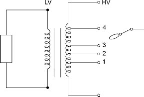
Figure 1.68 Off-load Tap Changing
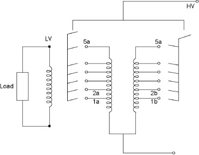
Figure 1.69 On-load Tap Changing with Two Primary Windings
1.47 ON-LOAD TAP-CHANGING TRANSFORMERS
Figure 1.69 shows the on-load tap-changing transformers, which are commonly used in modern days to ensure the reliable power supply.
The voltage at the secondary side is minimum when the switches A and B are closed as well as the switches 1a and 1b are closed. The following steps are followed to increase the voltage:
- The switch A is opened at first followed by the switch 1a. The entire load is shared by winding B only. The switch 2a is closed at first followed by switch A.
- The switch B is opened at first followed by the switch 1b. The entire load is shared by winding A only. The switch 2b is closed at first followed by switch B.
The main function of the additional switches A and B is to avoid the arcing on tap-changing switches. The following are the main disadvantages of on-load tap-changing transformers:
- Number of tapping is equal to two times the number of step voltages.
- Since the change in impedance of the transformer occurs during switching operation, it causes the voltage surge.
- It is very difficult to design a transformer with two windings.
1.48 ON-LOAD TAP CHANGER WITH SINGLE PRIMARY WINDING
Figure 1.70 shows the on-load tap changer with single primary winding, which overcomes the disad-vantages of on-load tap-changing transformers. An additional inductor with mid-point tapping is used in this method. The maximum voltage is obtained on the LV side when the switches A and B are closed and the switches S1 and S2 are in position.
- The following sequences performed to change the sequence of voltage:
- Open A, Open S1, Close S1 on 2 and Close A.
- Open B, Open S2, Close S2 on 2 and Close B.
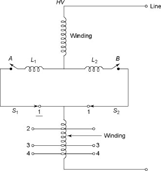
Figure 1.70 On-load Tap Changer with Single Primary Winding
When S1 is changed from 1 to 2, very few turns between the tapping 1 and 2 will be momentarily short-circuited. L1 and L2 are provided to reduce the heavy short circuited currents during the change over taps. Current flows in the L1 and L2 are in opposite direction during normal operations and hence impedance drop can be neglected.
1.49 PREVENTIVE AUTOTRANSFORMER
Figure 1.71 shows on-load tap changing devices with preventive autotransformer. The short circuiting switch (S) is closed during the normal operation and the tap 1 is also closed, which gives the highest voltage on LV side. The following steps are followed to raise the voltage:
- The switch (S) is opened.
- Tap-2 is closed.
- Tap-1 is opened.
- S is closed.
The taps 1 and 2 are closed during the changeover of switches, and at that time part of the main winding is short-circuited by the autotransformer. The reactance of autotransformer is made large to minimize the short circuit currents. The flow of currents in the two halves of autotransformer is in the opposite directions, and hence the voltage drop in the autotransformer is negligible. The sliding contacts are used instead of switches. Since the autotransformer avoids the short circuit during switching operation, hence the name is preventive autotransformer.
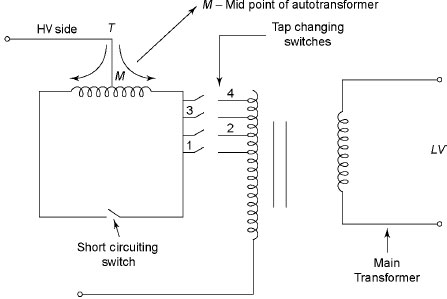
Figure 1.71 Tap Changing with Preventing Autotransformer
1.50 BOOSTER TRANSFORMER
Figure 1.72 shows the regulating transformer along with booster transformer. Booster transformers are useful in controlling the voltage when the tap-changing gear is not convenient to be accommodated with the main transformer. Booster transformers are also used to increase the voltage at the middle of the line. The main transformer maintains the constant voltage at the terminals S-S. The voltage at the middle of the line and load end can be controlled by the booster transformer. The following are the advantages of the booster transformer:
- The operation of the regulation transformer does not depend on the main transformer. If the main transformer fails, it will throw the latter.
- It is cheaper.
Figure 1.72 Booster Transformer
- It needs less space and it has less losses.
- It is economical to use booster transformer along with large transformers because the cost of the tap changing gear is independent of the size.
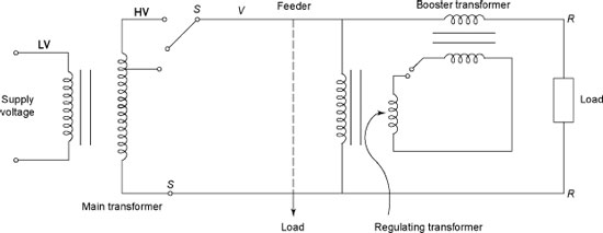
1.51 INRUSH PHENOMENON
An unloaded transformer switched on to a supply s is shown in Figure 1.73.
If the flux in transformer be Φ = Φm sinωt, the induced voltage can be expressed by
![]()
Since the applied voltage is exactly equal to the induced voltage, the flux lags behind the applied voltage by an angle 90° in steady state shown in Figure 1.74.
Figure 1.75 shows that the flux is at its negative maxima when the voltage is passing through the zero. The flux changes from –Φm to Φm in a time equal to T/2. Therefore, in time T/2, the change in flux is 2Φm.
Let the transformer be switched on at positive zero crossing of the voltage waveform shown in Figure 1.75 and also the residual flux be zero. Therefore, the initial value of flux is zero and the flux subsequently must have the same rate of change of flux. The waveform will be the same as in the steady state and hence the flux will reach the peak value of +2Φm in half a cycle. The power transformers operate near the knee of the saturation curve. The flux demand of +2Φm causes the transformer core deep into the saturation. This causes to draw large magnetizing current with a peaky non-sinusoidal waveform, which is of the order of 8–30 times the full load current known as inrush current having time constant of this transient component of current of the order of a few seconds at worst.
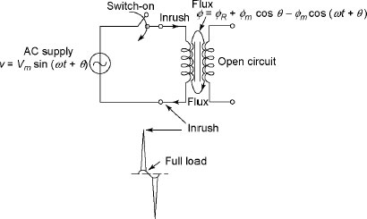
Figure 1.73 Switch on an Unloaded transformer
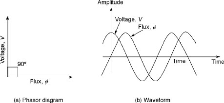
Figure 1.74 Flux and Applied Voltage
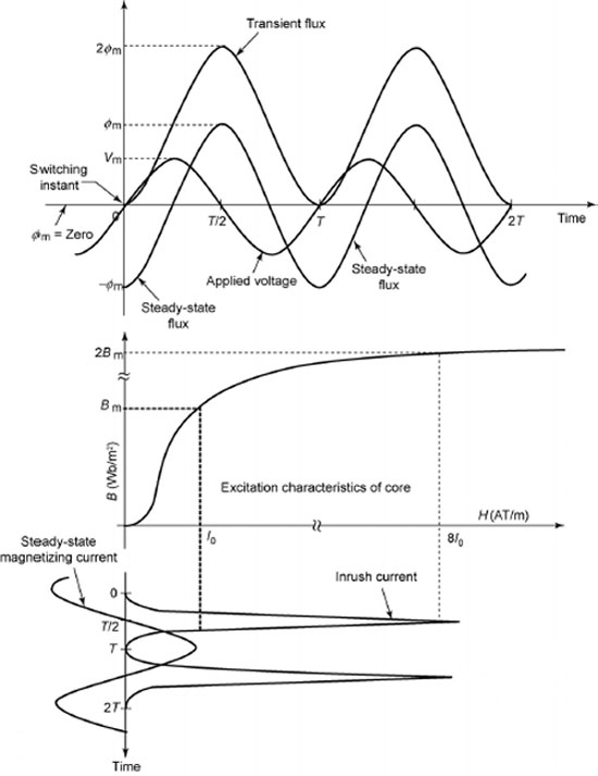
Figure 1.75 Phenomenon of Inrush
ADDITIONAL SOLVED PROBLEMS
Example 1.21 The net cross-sectional area of a single-phase, 50 Hz transformer is 500 cm2 having 400 and 100 turns in the primary and secondary winding, respectively. If it is connected to a 230 V, 50 Hz supply, calculate the following:
Solution
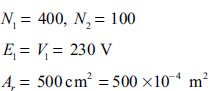
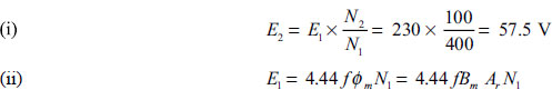
![]()
Example 1.22 The details of a single-phase transformer are shown below.
Primary turns = 600, secondary turns = 60
Primary applied voltage = 3000 V, Frequency = 50 Hz
Mean length of the circuit = 152 cm with the joints equivalent to an air gap of 0.12 mm
Maximum flux density = 1.2 Wb/m2
Iron loss at this flux density = 4.1 W/kg of iron
Density of iron = 7.7 g/cm3
Ampere turns / cm at this flux density = 6
Calculate the no-load primary current and no-load power factor of this transformer.
Solution
We know that
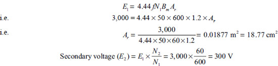
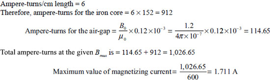
RMS value of magnetizing current (Iμ)=![]()
Length of iron path = 152 cm and its area of cross-section = 18.77 cm2
∴ Volume of iron core = 152 × 18.77 = 2853.04 cm2
Here, density of iron = 7.7 g / cm3
Mass of iron =![]()
Total iron loss = 21.97×14.4 = 316.97 W
Iron loss component of the no-load primary voltage current (Ic)=![]()
No-load primary current (I0)=![]()
No-load power factor(cosθ0)=![]()
Example 1.23 The ratio of the number of turns of primary and secondary windings is 5. The load current on the secondary is 120 A at 0.8 lagging power factor. The primary current is 27A at 0.72 power factor lag-ging. Find the no-load current of the transformer and its phase with respect to the voltage. Neglect the angle between –E1 and V1.
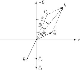
Figure E1.5
Solution
Turns ratio (a) = 5
Secondary current = 120 A
Power factor (cosθ2) = 0.8, i.e., θ2 = 36.87°
Primary current = 27 A
Power factor (cosθ1)= 0.72, i.e., θ1 = 43.94°
After resolving ![]() into their x and y components, we have
into their x and y components, we have

![]()
![]()
![]()
Dividing Equation (2) by Equation (1), we have
![]()
θ0=86.84°
From Equation (1), we have
![]()
∴ No-load current is 4.354 A, and the angle between no-load current and voltage is 86.84°.
Example 1.24 The data of a single-phase transformer are shown below: Turns ratio (a) = 10, R1 = 4.95 Ω, X1 = 7.86 Ω, R2 = 0.18 Ω, X1 = 0.38 Ω, no-load current leads the flux by an angle 8°. The value of no-load current is 1.4 A. A load of power factor 0.8 lagging is connected to the secondary so that the load current is 120 A at a terminal voltage of 350 V. Calculate the following with the help of phasor diagram:
- Primary applied voltage.
- The primary power factor.
- The efficiency of the transformer.
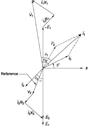
Figure E1.6
Solution
- Primary applied voltage: Let us take V2 as reference.
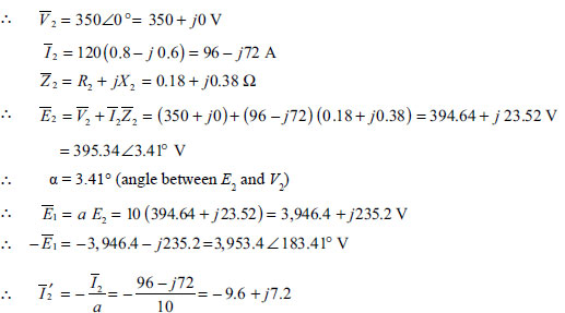
The angle between I0 and V2 is 3.41° + 90° + 8° = 101.41°
![]()
∴ Primary current,

- The primary applied voltage = |V1| = 4,071.65 V
- The primary power factor = cosθ1 = cos (183.80° – 139°) = 0.7095 (lagging)
- Here θ0 = 183.80° – 183.41° + 90° – 8° = 82.39°
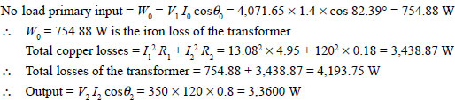
Example 1.25 A single-phase transformer has the following data:
Turns ratio (a) = 10:1, Z1 = 1.6 + j 4.3 Ω, Z2 = 0.019 + j 0.048 Ω
The input voltage of the transformer is 5,000 V and the load current at the secondary is 250 A at 0.8 lagging power factor. Neglect no-load current. Calculate secondary terminal voltage and output power.
Solution
![]()
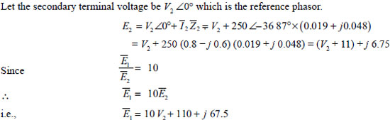
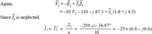
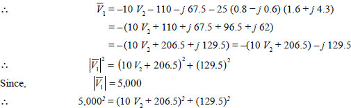
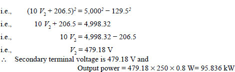
Example 1.26 The maximum flux density of a 600 kVA, 2,000/400 V, 50 Hz, single-phase transformer is 1.2 Wb/m2 having a net cross-sectional area of 0.05 m2.
- Find (a) the number of primary and secondary turns, (b) the magnetizing current and (c) the efficiency of the transformer at full-load and 0.8 power factor lagging.
The mean length of the magnetic circuit is 1.1 m and relative permeability is 1,200. The net respective power input during short circuit test and open circuit test are 720 W and 360 W.
- If this transformer is connected to the supply having similar voltage but frequency of 100 Hz, comment on the effect on efficiency.
Solution

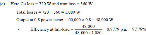
- Hysteresis loss (Ph)∞ f and eddy current loss (Pe) ∞ f2. Therefore, Ph becomes double and Pe becomes four times.
Hence, overall losses will increase and efficiency of the transformer will decrease.
Example 1.27 A8 kVA, 500/250 V, 50 Hz, single-phase transformer gave the following test data:
OC test (LV side): 250 V, 1.2 A, 80 W
SC test (HV side): 25 V, 12.5 A, 90 W, where LV refers to low voltage and HV refers to high voltag.
Determine the following:
- Equivalent circuit referred to as LV side.
- Secondary load voltage at 0.8 power factor lagging with full-load current.
Solution
OC test:
Instruments placed on LV side and HV side is kept open.
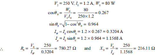
SCtest:
Instruments placed on HV side and LV side is short-circuited:
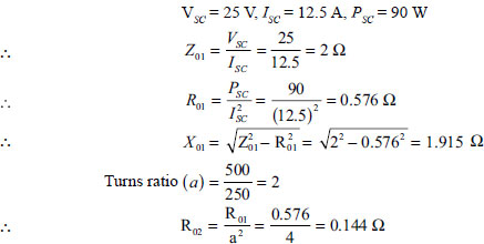

Example 1.28 The turn ratio of a single-phase transformer is 4. The resistance and leakage reactance of HV winding are 1.4 Ω and 6 Ω respectively. The resistance and leakage reactance of LV winding are 0.06 Ω and 0.04 Ω respectively. If 200 V, 50 Hz is applied to HV winding and LV winding is short-circuited, find the following: (i) current in LV winding, (ii) copper loss in the transformer and (iii) power factor.
Solution
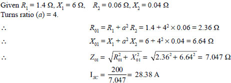
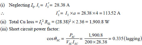
Example 1.29 A single-phase, 4 kVA, 250/125 V, 50 Hz transformer has the following parameters:
Resistance: primary 0.9 Ω, secondary 0.94 Ω
Leakage reactance: primary 0.4 Ω, secondary 0.11 Ω
Resistance and reactance of equivalent exciting circuit referred to primary are R0 = 700 Ω and X0 = 250 Ω respectively. Find the instruments reading for OC and SC tests when supply in given to HV side. During SC test, full-load current flows.
Solution
Here
R1 = 0.9 Ω, X1 = 0.94 Ω
R2 = 0.4 Ω, X2 = 0.11 Ω
![]()
OC test:
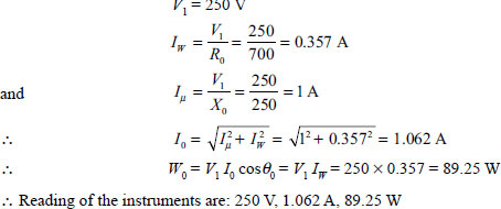
SC test:
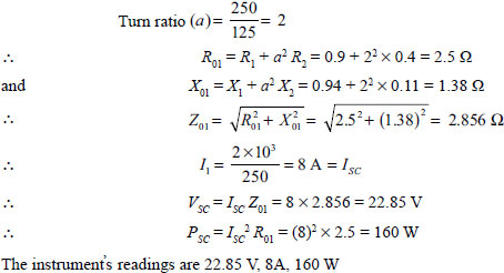
The instrument’s readings are 22.85 V, 8A, 160 W
Example 1.30 A10 kVA, 500/250 V, 50 Hz, single-phase transformer has the following test results:
OC test: 500 V, 1.2 A, 80 W
SC test: 50 V, 15 A, 90 W (LV side is short-circuited)
Determine the regulation and efficiency of the transformer at full load and at 0.8 power factor lagging.
Solution
From OC test of the transformer, iron loss of the transformer = 80 W
SC test:
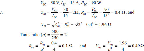
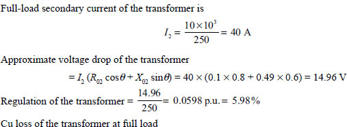
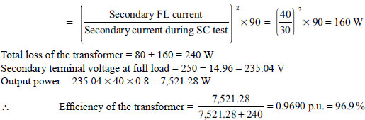
Example 1.31 A 4 kVA, 200/400 V, 50 Hz, single-phase transformer gave the following test results:
OC test (LV side): 200 V, 0.8 A, 75 W
SC test (HV side): 20 V, 10 A, 90 W
Calculate the parameters of the transformer referred to as LV side. Find the regulation and efficiency of the transformer for full load and half load both at 0.8 power factor lagging.
Solution
OC test:
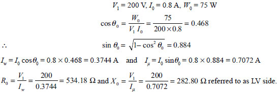
SC test:
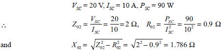

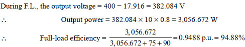
Example 1.32 A 6 kVA, 250/500 V, 50 Hz, single-phase transformer has the following test results:
OC test (LV side): 250 V, 1.2 A, 80 W
SC test (HV side): 25 V, 10 A, 95 W
Calculate the circuit parameters referred to as LV side. Also calculate the regulation and efficiency of the transformer at full load and half load at 0.8 power factor lagging.
Solution
![]()
OC test:
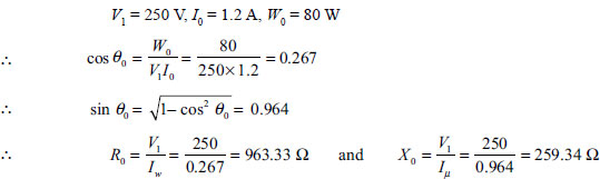
SC test:
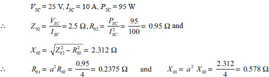
The voltage drop due to lagging p.f. is expressed by
![]()
Full load:
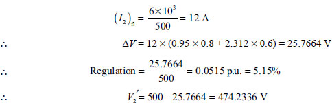
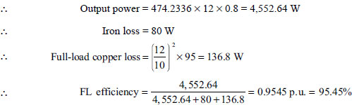
Half load:
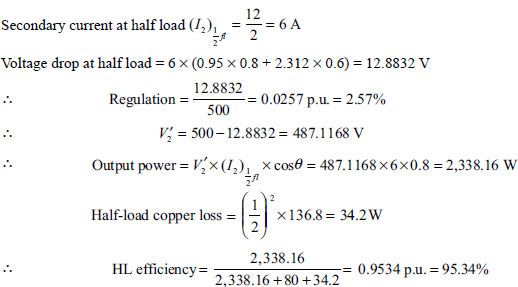
Example 1.33 A 40 kVA single-phase step-down transformer has a full-load secondary current of 200 A, and the total resistance referred to as secondary is 0.008 Ω. Find the efficiency of the transformer at full-load and three-fourth load when the load is at (i) unity power factor and (ii) 0.8 power factor. The iron loss of the transformer is 190 W.
Solution
Full-load secondary current = 200 A
![]()
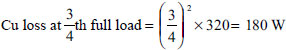
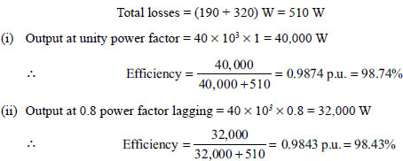
At 3/4th load:
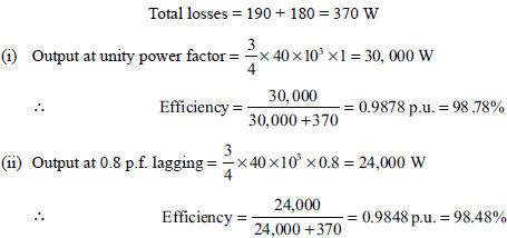
Total losses = 190 + 180 = 370 W
Example 1.34 A 20 kVA single-phase transformer has iron loss of 250 W and full-load Cu loss of 500 W.
- Determine the load at which maximum efficiency occurs and the value of maximum efficiency at unity power factor.
- If the maximum efficiency occurs at 85 per cent of full load, calculate the new core loss and full-load Cu loss assuming that total loss at full load remains constant.
Solution
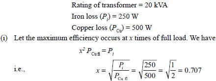
Maximum efficiency occurs at 70.7 per cent of full load.
Output at unity power factor = 0.707 × 20 × 1 = 14.14 kW
Total losses = 2 × 250 = 500 W = 0.5 kW
![]()
Maximum efficiency occurs at 85 per cent of full load.
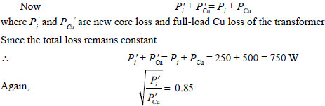
![]()
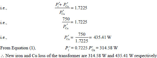
Example 1.35 A single-phase, 1,000/200 V transformer has primary and secondary resistances of 0.25 Ω and 0.018 Ω respectively. If iron loss of the transformer is 240 W, calculate the secondary current at which maximum efficiency occurs. Also calculate the maximum efficiency at 0.8 power factor lagging. Assume that secondary terminal voltage remains constant.
Solution
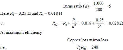
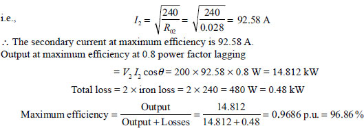
Example 1.36 A single-phase, 150 kVA transformer has an efficiency 96 per cent at full load on 0.8 power factor and 96.5 per cent at half load on 0.8 power factor lagging. Find the following:
- Iron loss.
- Copper loss at full load.
- The load kVA at which maximum efficiency occurs.
- The maximum efficiency of the transformer at 0.8 power factor lagging.
Solution
Let Pi and PCu be the iron loss and full-load copper loss of the transformer, respectively. Full-load efficiency is 96 per cent at 0.8 p.f. lagging
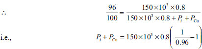
Half-load efficiency is 96 per cent at 0.8 p.f. lagging
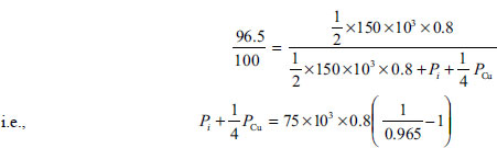
![]()
Solving Equations (1) and (2), we have
PCu = 3,764.98 W
and Pi = 1,234.92 W
- Iron loss of the transformer = 1,234.98 W
- Full-load copper loss of the transformer = 3,764.98 W
- Let × be the fraction of full load to get the maximum efficiency of the transformer.
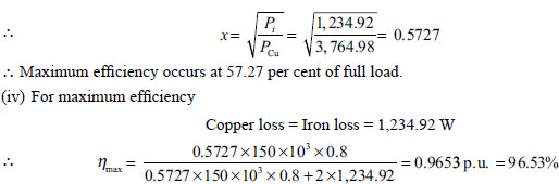
Example 1.37 A12kVA, 1,200/400 V, single-phase,50Hz transformer has the following test results:
OC test (HV side): 1,200 V, 1.2 A, 70 W
SC test (LV side): 30 V, 22 A, 80 W
Find the following:
- Core loss of the transformer.
- Equivalent resistance and leakage reactance of the transformer referred to as LV side.
- Equivalent resistance and leakage reactance of the transformer referred to as HV side.
- Calculate the secondary winding voltage to keep the secondary terminal voltage 400 V at full load and 0.8 power factor lagging. Hence calculate the primary supply voltage.
- Regulation of the transformer at full load and 0.8 power factor lagging.
- Regulation of the transformer at full load and 0.8 power factor leading.
- Power factor of the load so that regulation of the transformer is maximum at full-load current. Also find the regulation.
- Power factor of the load so that regulation of the transformer is zero.
- Efficiency of the transformer for: (a) full load, (b) half load, (c) -th load and (d) -th load at 0.8 power factor lagging. In all cases, terminal voltage remains 400 V. 4
- Find the load at kVA at which efficiency of the transformer becomes maximum. Find the maximum efficiency at 0.8 power factor lagging.
Solution
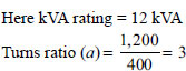
- Core loss of the transformer = 70 W (from OC Test)
- SC test: Instruments placed on LV side (side 2).
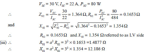
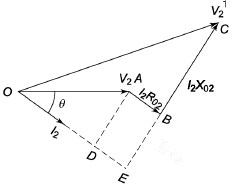
Figure E1.7
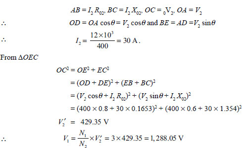
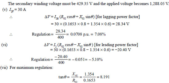
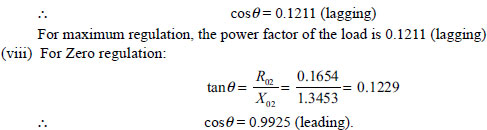

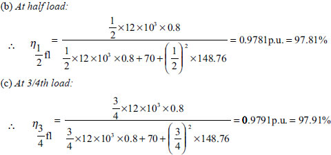
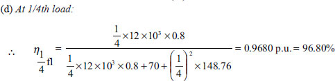
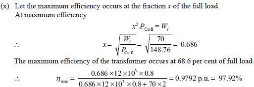
Example 1.38 The short circuit test data referred to as HV side of two single-phase transformers 1,000/200 V are
Transformer A: 50 V, 25 A, 375 W
Transformer B: 37.5V, 25 A, 500 W
If two transformers are connected in parallel and fed a total load of 18.176 kW at 0.8 power factor lagging, calculate the secondary load current, power factor and power output of each transformer.
Solution
For transformer A:
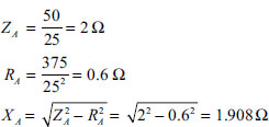
For transformer A:

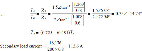
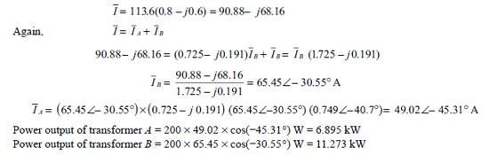
Example 1.39 Find the all-day efficiency of a transformer having maximum efficiency of 98.5 per cent at 20 kVA at unity power factor and loaded as follows:
11 hours: 5 kW at 0.7 power factor lagging
6 hours: 8 kW at 0.8 power factor lagging
7 hours: no load.
The maximum efficiency of the transformer occurs at 80 per cent of full load.
Solution
At maximum efficiency:
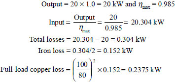
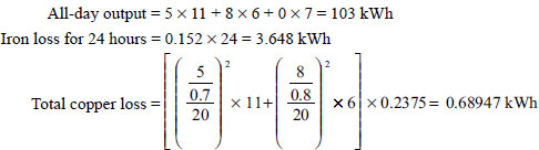
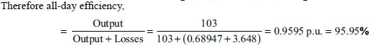
Example 1.40 Two single-phase transformers A and B are connected in parallel on both primary and secondary. Transformer A has full-load resistance drop of 1.2 per cent and reactance drop of 6.5 per cent, while the corresponding values of transformer B are 1 per cent and 5.5 per cent, respectively. Find the sharing of each of the load for the following cases:
- 150 kW at 0.8 power factor lagging.
- 160 kW at 0.9 power factor lagging.
Solution
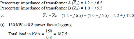
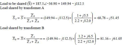
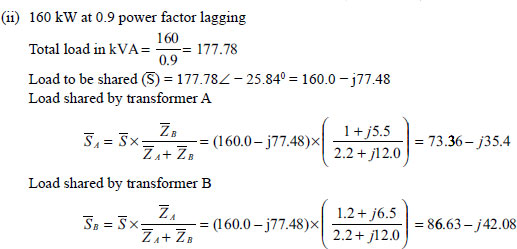
Example 1.41 A 1,000 kVA single-phase transformer has a percentage impedance of (1.2 + j 4.8), while a 400 kVA single-phase transformer has a percentage impedance of (2.2 +j 6.5). These two transformers are connected in parallel. The no-load voltage of each transformer is 600 V If the total load is 800 kVA at 0.8 power factor lagging, find the load shared by each of the transformers.
Solution
Let 1,000 kVA and 400 kVA transformers be denoted by A and B, respectively.
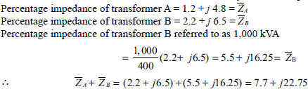
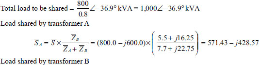
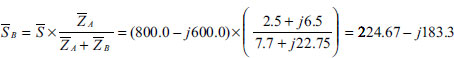
Example 1.42 Two single-phase transformers A and B have the following parameters:
Transformer A: 10 kVA, 400/200 V, percentage resistance and reactance are 4 per cent and 5 per cent, respectively.
Transformer B: 5 kVA, 400/200 V, percentage resistance and reactance are 5 per cent and 4 per cent, respectively.
When these two transformers are connected in parallel, they share a common load of 12 kW at 0.8 power factor lagging. Calculate the active and reactive power delivered by transformer A and transformer B.
Solution
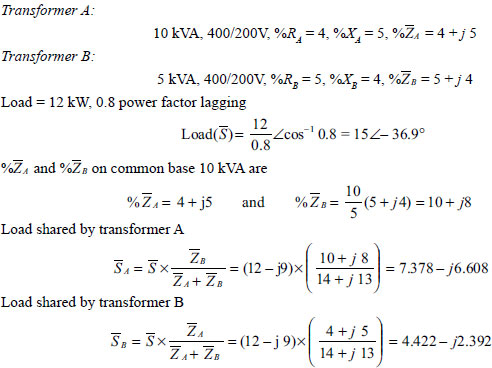
Example 1.43 Two single-phase transformers with voltage ratio 1,000/200 V have the following short circuit data:
Transformer A: Primary voltage = 55 V, primary current = 25 A, power input to primary = 500 W
Transformer B: Primary voltage = 40V, primary current = 25 A, power input to primary = 610 W
The two transformers are connected in parallel and share a common load of 24 kW at 0.8 power factor lagging. Calculate the secondary load current, power factor and real power output of each transformer.
Solution
Transformer A:
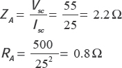


Example 1.44 Two single-phase transformers A and B are connected in parallel for supplying a load, which has resistance and reactance of 12 Ω, and 6 Ω,, respectively. The effective resistance and reactance of transformer A are 0.12 Ω and 1.3 Ω respectively, and that of transformer B are 0.17 Ω and 1.6 Ω respectively. The no-load emf of transformer A is 2,400 V and that of transformer B is 2,300 V. Calculate the following:
- Circulating current at no load.
- Current output of each transformer and its power factor.
- Power delivered by each transformer.
Solution
No-load emf of transformer A (EA) = 2,400 V
No-load emf of transformer B (EB) = 2,300 V
RA= 0.12 Ω, XA = 1.3 Ω, RB = 0.17 Ω, XB = 1.6 Ω
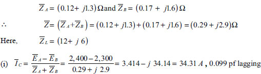
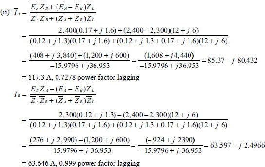
![]()
Example 1.45 Two single-phase transformers A and B having ratings 600 kVA and 300 kVA share a load of 800 kVA at unity power factor. The open circuit voltage of transformer A and transformer B are 610 V and 600 V, respectively. Percentage resistance and reactance of transformer A are 1.2 and 3.3 respectively, and that of transformer B are 1.7 and 5.7 respectively. Calculate the circulating current in the secondary at no load, current output of each transformer and its power factor and sharing of load by transformer A and transformer B.
Solution
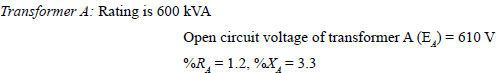
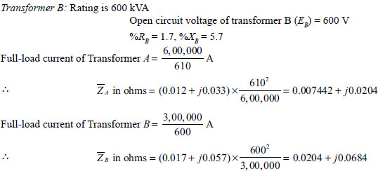
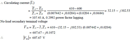
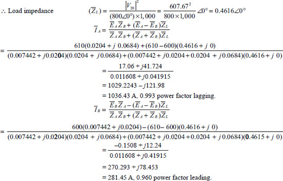
Load shared by transformer A = 607.67 × 1036.43 ∠–6.76° VA = 629.807 ∠–6.76°p kVA
Load shared by transformer B = 607.67 × 281.45 ∠16.26° VA = 171.028 ∠16.26° kVA
Example 1.46 A 100 kVA, 2,000/400V, single-phase two-winding transformer is to be used as an autotransformer for stepping up the voltage from 2,000 V to 2,400 V. At rated load, the two-winding transformer has 2.4 per cent loss, 3.4 per cent voltage regulation and 4.2 per cent impedance. Calculate the following for an autotransformer:
- Voltage and current rating.
- kVA rating.
- Efficiency.
- Percentage impedance.
- Regulation.
- Short circuit current on each side.
Solution
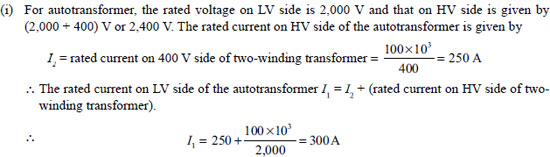
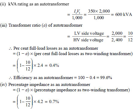
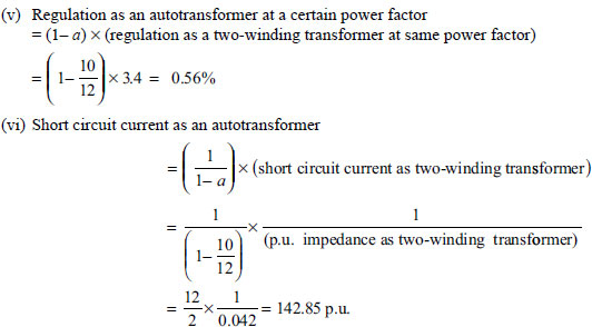
SIGNIFICANT POINTS
EMF Equation
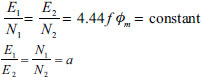
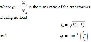
Equivalent Resisance
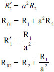
Equivalent Reactance
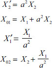
Open Circuit Test
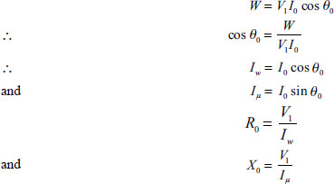
Short Circuit or Impedance Test
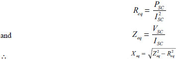
Voltage Regulation of a Transformer
Voltage Regulation Down
![]()
Voltage Regulation Up
If inherent voltage drop is divided by V2, it is known as voltage regulation up. Mathematically, we can write it as
![]()
The voltage regulation up is expressed mathematically by

Positive sign is for lagging power factor and negative sign for leading power factor.
Zero Voltage Regulation
Condition for Maximum Voltage Regulation
![]()
Maximum Efficiency
![]()
Load Current at Maximum Efficiency
kVA Supplied at Maximum Efficiency (V2 Constant)
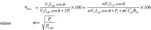
SHORT QUESTIONS AND ANSWERS
Q.1 What is the power factor of a transformer?
Ans. At no load, the power factor of a transformer is very low and lagging, whereas the power factor on load is nearly equal to the power factor of the load, which it is carrying.
Q.2 What is the normal phase difference between the voltage and the no-load current in a trans-former?
Ans. The no-load current in a transformer normally lags behind the voltage by about 80° – 85°.
Q.3 What are the essential parts of a transformer?
Ans. The essential parts of a transformer are as follows:
- Magnetic circuit consisting of laminated iron core and clamping structure
- Primary winding
- Tank filled with insulating oil
- HT terminals with bushings
- LT terminals with bushings
- Conservator tank
- Breather
- Vent pipe
- Thermometer
Q.4 What is the name of the winding to which supply is given?
Ans. Primary winding.
Q.5 What is the name of the winding from which the supply is taken for load connections?
Ans. Secondary winding.
Q.6 Which material is used for the core of a transformer and why?
Ans. Laminations of specially alloyed silicon steel (silicon content 4–5 per cent) are used due to its high electrical resistance, high permeability, non-ageing characteristics and minimum iron loss.
Q.7 What is the use of iron core in a transformer?
Ans. The iron core is used in a transformer to provide continuous easy magnetic path of low reluctance.
Q.8 How is magnetic leakage reduced?
Ans. Magnetic leakage is reduced to a minimum by sectionalizing and interleaving the primary and secondary windings.
Q.9 Why are iron cores in transformers made laminated?
Ans. Iron cores are made laminated to reduce eddy current loss.
Q.10 What determines the thickness of the lamination or stamping?
Ans. Frequency determines the thickness of the lamination or stamping.
Q.11 Why are the laminations insulated from each other?
Ans. The laminations are insulated from each other by insulating varnish or thin paper to break the path of eddy currents and thus reduce eddy current loss.
Q.12 What is stacking factor? What is its approximate value?
Ans. Stacking factor is the ratio of iron content in the laminated varnished core by volume. Its value is about 90 per cent, that is, 10 per cent volume is occupied by varnish and air.
Q.13 What is called grain-oriented laminations?
Ans. Grain-oriented laminations are cold rolled laminations specially annealed to orient the iron crystals, that is, the grains in a uniform way in the direction of rolling to get very high permeability and low hysteresis loss.
Q.14 What is the permissible maximum flux density in transformer core?
Ans. 1.6–1.8 Wb/m2.
Q.15 What is the phase relationship between the primary and secondary voltages of a transformer?
Ans. The primary and secondary voltages of a transformer are 180° out of phase.
Q.16 What is turn ratio of a transformer?
Ans. The ratio of the number of turns in the primary to the number of turns in the secondary windings is called the turn ratio or the ratio of transformation of the transformer, which is indicated by a constant.
![]()
Q.17 What is voltage ratio of a transformer?
Ans. Voltage ratio is the ratio of the voltage between the line terminals of one winding to that between the line terminals of another winding at no load.
Q.18 What current flows in the transformer primary when its secondary is open?
Ans. When the secondary is open, there is no current in the secondary of the transformer. The primary takes a small current I0) from the source called no-load current which has a magnetizing com-ponent (I0 sinθ0) producing the magnetic flux and a working component (I0 cosθ0) supplying real power for iron losses.
Q.19 What is the formula for calculating no-load current?
Ans. No-load current ![]()
Q.20 Why is the frequency not changed during transformation of electrical energy in a transformer?
Ans. As the same flux having a definite frequency is responsible for the production of emf on both the primary and secondary windings, there is no question of change in the frequency.
Q.21 What is the emf equation of a transformer?
Ans. Erms = 4.44 Φm fN V
where Φm = maximum value of the flux linkage with both the windings, f = frequency of the supply, N = number of turns.
Q.22 What are the two basic types of transformers?
Ans. The two basic types of transformers are:
- The isolation type in which the two windings are physically isolated and electrically insulated from each other.
- The autotransformer type in which one coil is used for both the windings.
Q.23 What are the types of transformers according to the arrangement of iron cores?
Ans. There are three types: (i) core type, (ii) shell type and (iii) distributed core or Berry type.
Q.24 What magnetic circuit is formed in Berry-type constructions and why?
Ans. Distributed magnetic circuits are formed in Berry-type construction because of its distributed cores.
Q.25 What is called limb of a transformer?
Ans. The vertical portion of the iron core where the windings are placed is called limb of a transformer.
Q.26 Why are LT windings placed near the core?
Ans. LT windings are placed near the core to reduce the total dielectric strength of the insulating mate-rials provided on the winding.
Q.27 What are the types of windings according to the construction?
Ans. Sandwich type and cylindrical type.
Q.28 What is the difference between cylindrical-type and sandwich-type winding?
Ans. In cylindrical-type winding, the length of the coils is equal to the length of the core limb. The pri-mary and secondary windings are placed one over the other, placing low-voltage winding nearer the core, whereas in sandwich-type winding HT and LT windings are placed lengthwise one above and other like a sandwich.
Q.29 What are the types of transformers according to its location?
Ans. (i) Indoor-type transformer (ii) Step-down transformer.
Q.30 What do you mean by step-up and step-down transformers?
Ans. When a transformer converts low voltage to high voltage it is called a step-up transformer, and when the transformer converts high voltage to low voltage it is called a step-down transformer.
Q.31 What are the advantages of using a transformer in an AC supply?
Ans. The transformer has the following advantages:
- Voltage can be transformed from low voltage to high voltage for transmission and high voltage to low voltage for distribution without changing the frequency.
- As the transformer has no rotating parts, there is no factional loss and wear and tear is minimum.
- A high voltage or an extra high voltage can be transformed easily by providing good insulation.
- Its maintenance cost is low.
- Practically it requires very little attention for its operation.
Q.32 What is an ideal transformer?
Ans. A transformer having an overall efficiency of 100 per cent is called an ideal transformer.
Q.33 What do you mean by power transformer?
Ans. Transformers that are used on transmission lines for the transmission and distribution of relatively large quantities of energy are called power transformers.
Q.34 What do you mean by distribution transformers?
Ans. When transformers are used for distributing the energy from transmission lines as well as net-works for local consumption and the secondaries are directly connected to the consumer's load, they are called distribution transformers.
Q.35 What do you mean by lighting transformer?
Ans. A transformer used to supply a distribution circuit having no motors connected to it is called light-ing transformer.
Q.36 How does a transformer contribute towards the widespread popularity of AC system over DC?
Ans.
- High voltage of AC system can be obtained using a transformer for transmission of electrical power.
- Using a transformer, AC voltage can be increased or decreased without any power loss.
SUPPLEMENTARY PROBLEMS
- A single-phase transformer has 400 primary and 1,000 secondary turns. The net cross-sectional area of the core is 60 cm2. If the primary winding be connected to a 50 Hz supply at 500 V, calculate (i) the peak value of the flux density in the core and (ii) the voltage induced in the secondary winding.
[Ans.0.9384 T; 1,250 V]
- The emf per turn of a single-phase 10 kVA, 2,200/220 V, 50 Hz transformer is 10 V. Calculate (i)the number of primary and secondary turns and (ii) the net cross-sectional area of the core for a maximum flux density of 1.5 T.
[Ans.(i)220,22(ii)0.03m2]
- The no-load current of a transformer is 5 A at 0.25 power factor when supplied at 235 V, 50 Hz. The number of turns on the primary winding is 200. Calculate (i) the maximum value of flux in the core, (ii) the core loss and (iii) the magnetizing component.
[Ans. (i) 5.293 mWb, (ii) 293.75 W (iii) 4.84 A]
- A 50 kVA, 4,400/220 V, single-phase transformer has R1 = 3.45 Ω, R2 = 0.009 Ω. The values of reactances are X1 = 5.2 Ω and X2 = 0.015 Ω. Calculate the following:
- The equivalent resistance referred to primary.
- The equivalent resistance referred to secondary.
- The equivalent reactance referred to both primary and secondary.
- Equivalent impedance referred to both primary and secondary.
- Total Cu loss.
[Ans. (i) 7.05 Ω, (ii) 0.0176 Ω, (iii) 11.2 Ω, 0.028 Ω, (iv) 13.23 Ω, 0.0331 Ω, (v) 909 W]
- A 5 kVA, 400/200 V, single-phase, 50 Hz transformer gave the following test results:
Open circuit: 400 V, 1A, 50 W
Short circuit: 12 V, 10 A, 40 W
The instruments are placed on the same side during these two tests. Determine the following:- The component of the no-load current.
- The efficiency and regulations at full load and 0.8 power factor lagging.
[Ans. (i) Iw = 0.125 A, Iμ = 0.922 A (ii) Efficiency = 97.72% Regulation = 3.13 per cent]
- The primary and secondary windings of a 500 kVA, single-phase transformer have resistances of 0.4 Ω and 0.0015 Ω respectively. The primary and secondary voltages are 6,000 V and 400 V, respectively. The iron loss is 3.2 kW. Calculate the efficiency on (i) full load and (ii) half load, assuming power factor of load to be 0.8.
[Ans.(i) 97.962%, (ii)97.81%]
- A 4 kVA, 200/400 V, 50 Hz, single-phase transformer gave the following test results:
Open circuit: 200 V, 0.7, 60 W (instruments placed on LV side)
Short circuit test: 9 V, 6 A, 21.6 W (instruments placed on HV side)
Determine (a) the magnetizing current and the component corresponding to iron loss at normal voltage and frequency, (b) the efficiency on full load at unity power factor and (c) the secondary terminal voltage on full load at power factors of unity, 0.8 lagging and 0.8 leading.[Ans. (a) 0.63 A, 0.3 A; (b) 97.1%; (c) 394 V, 387 V, 403.4 V]
- A 100 kVA, 50 Hz, 440/11,000 V, single-phase transformer has an efficiency of 98.5 per cent when supplying full-load current at 0.8 power factor and an efficiency of 99 per cent when supplying half of full-load current at unity power factor. Find the iron and copper losses corresponding to full-load current. At what value of load current will maximum efficiency be attained?
[Ans. Iron loss = 267.3 W Cu loss = 951 W, load current = 120 A]
- The maximum efficiency of a 500 kVA, 3,300/500 V, 50 Hz, single-phase transformer is 97 per cent and occurs at -th of full load, unity power factor. If impedance is 10 per cent, calculate the regulation at full load, power factor 0.8 lagging.
[Ans. 6.88%]
- A 5 kVA, 500/250 V, 50 Hz, single-phase transformer has the following test data:
OC test (LV side): 250 V, 2.5A, 80 W
SC test (HV side): 20 V, 14 A, 95 W
Find the following: (i) equivalent circuit referred to as primary side and (ii) secondary load voltage on full load at 0.8 power factor lagging.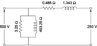
FIGURE A1
[Ans. (i)Figure A1(ii)242.59 V]
- The following test results were obtained in 300/600 V, single-phase, 50 Hz transformer:
OC test (LV side): 300 V, 1.5 A, 90 W
SC test (HV side): 22 V, 13 A, 120 W
Determine (i) the circuit constants referred to as LV side, (ii) the applied voltage and efficiency when the output is 10 A at 600 V at 0.8 lagging power factor.[Ans. (i) R0 = 1,000 Ω, X0 = 204.3 Ω, R01 =0.177 Ω, X01 = 0.384 Ω (ii) Applied voltage = 307.46 Efficiency = 96.75%]
- A 200/400 V, 20 kVA, 50 Hz single-phase transformer is connected as an autotransformer to work off 600/200 V supplies. Calculate the kVA rating of the autotransformer. With load of 20 kVA, 0.8 power factor lagging connected to the 200 V terminals, calculate the currents in the load and in the two-winding sections.
[Ans. 30 kVA, 33.33A (600 V section), 66.67 A (200 V section)]
- A transformer has its maximum efficiency of 0.98 at 15 kVA at unity power factor. During the day it is loaded as follows:
12 hours – 2 kW at power factor 0.5
6 hours – 12 kW at power factor 0.8
6 hours – 18 kW at power factor 0.9
Find the all-day efficiency.[Ans. 0.97]
- Two transformers A and B are joined in parallel to the same load. Determine the current delivered by each transformer. Given: open circuit voltage 6,600 V for A and 6,400 V for B. Equivalent leakage impedance in terms of secondary = 0.3 + j 3 for A and 0.2 + j 1 for B. The load impedance is 8 + j 6.
[Ans. 195 A, 422 A]
- Two 100 kW single-phase transformers are connected in parallel both on primary and on secondary. One transformer has an ohmic drop of 1/2 per cent at full load and an inductive drop of 8 per cent at full load. The other has an inductive drop of 4 per cent and an ohmic drop of 3/4 per cent. Show how they will share the following loads:
(a) 180 kW at 0.9 power factor.
(b) 120 kW at 0.6 power factor.[Ans. (a) 58.06 kW and 121.81 kW (b) 36 kW and 84 kW]
MULTIPLE-CHOICE QUESTIONS AND ANSWERS
- In a transformer
(a) All turns are equally insulated (b) The end turns are more strongly insulated (c) The end turns are closely wound (d) The end turns are widely separated - Laminated insulations coated with varnish are normally used in the transformer
(a) To reduce reluctance of magnetic path (b) To reduce the effect of eddy current (c) To increase the reluctance of magnetic path (d) To reduce the hysteresis effect - The required thickness of lamination in a transformer decreases when
(a) The applied frequency increases (b) The applied frequency decreases (c) The applied voltage increases (d) The applied voltage decreases - Oil in transformer is used to
(a) Transfer electrical energy (b) Insulate the windings (c) Cool the windings (d) None of the above - The following arrangement will reduce the reluctance of magnetic path of the transformer.
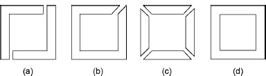
- The windings of a transformer are divided into several coils because
(a) It is difficult to wind as one coil (b) It reduces voltage per coil (c) It requires less insulation (d) None of the above - The size and construction of bushings in a transformer depend upon the
(a) Size of winding (b) Size of tank (c) Current flowing (d)Voltage supplied - Transformer humming sound is reduced by the
(a) Proper bracing of transformers assemblies (b) Proper insulation (c) Proper design (d) Proper design of winding - Sludge in transformer oil is due to
(a) Decomposition of oil (b) Decomposition of insulation (c) Moisture content in oil (d) None of the above - A transformer used only for electrical isolation between two circuits has turns ratio which is
(a) More than unity (b) Less than unity (c) Equal to unity (d) More than 0.5 - If 90 per cent of normal voltage and 90 per cent of normal frequency are applied to a transformer, the per cent charge in hysteresis losses will be
(a) 20% (b) 4.7% (c) 19% (d) 21% - If 110 per cent of normal voltage and 110 per cent of normal frequency is applied to a transformer, the percentage change of eddy current losses will be
(a) 10% (b) 20% (c) 25% (d) 21% - A transformer has two 2,400 V primary coils and two 240 V coils. By proper connection of the windings, the transformation ratio that can be obtained is
(a) 10 (b) 5 (c) 20 (d) 9 - A single-phase, 2,200/200 V transformer takes 1 A at the HT side or no load at a power factor of 0.385 lagging. The iron losses are
(a) 167 W (b) 77 W (c) 88 W (d) 98 W - Neglecting resistance, at constant flux density, the power required per kilogram to magnetize the iron core of a transformer is 0.8 W at 25 Hz and 2.04 W at 60 Hz. The power required per kilogram for 100 Hz is
(a) 3.8 W (b) 3.63 W (c) 3.4 W (d) 5.2 W - Select the correct statement:
(a) emf per turn of both the windings are equal (b) emf per turn in HV winding is more than the emf per turn in LV winding (c) emf per turn in HV winding is less than the emf per turn in LV winding - The flux involved in the emf equation of a transformer has
(a) rms value (b) Average value (c) Total value (d) Maximum value - The no-load current in a transformer lags the applied voltage by
(a) 90° – 95° (b) About 80° – 85° (c) 0° – 15° (d) About 110° - High leakage impedance transformers are used for applications such as
(a) Power distribution (b) Electrical toys (c) Arc welding (d) Fluorescent lamps - A transformer 2,000 kVA, 250 Hz is operated at 50 Hz. Its kVA rating should be revised to
(a) 400 kVA (b) 10,000 kVA (c) 2,000 kVA (d) Cannot be revised - The transformer which will have the largest size is
(a) 100 kVA, 25 Hz (b) 100 kVA, 100 Hz (c) 100 kVA, 50 Hz (d) 100 kVA, 60 Hz - The magnetic flux of a transformer follows
(a) High reluctance path (b) Low reluctance path (c) Low conductivity path (d) High conductivity path - The efficiency of a transformer is usually in the range of
(a) 50–60% (b) 65–75% (c) 70–90% (d) 90–98% - Transformer is laminated to reduce
(a) Hystersis loss (b) Eddy current loss (c) Partly (a) and partly (b) (d) Increases exciting current - Transformer changes the value of
(a) Power (b) Frequency (c) Voltage (d) Current - Transfer of electrical power from primary to secondary in a transformer takes place
(a) Electrically (b) Electromagnetically (c) Magnetically (d) None of these - The thickness of a 50 Hz transformer lamination is
(a) 0.35 cm (b) 0.35 mm (c) 0.33 m (d) 0.30 cm - A power transformer is a constant
(a) Current device (b) Voltage device (c) Power device (d) Main flux device - The value of flux in the emf equation of a transformer is
(a) rms (b) Average (c) Maximum (d) Integral wave cycle - The leakage flux in a transformer depends upon the value of
(a) Load current (b) Supply frequency (c) Mutual flux (d) None of these - The voltage regulation of a transformer at full-load 0.8 power factor lag is 6 per cent. Its voltage regulation at full-load 0.8 power factor lead will be
(a) Negative (b) 54% (c) Positive (d) Zero - The full-load efficiency of a transformer at 0.85 p.f. lag is 97 per cent. Its efficiency at full load 0.85 bpower factor lead will be
(a) 99% (b) 96% (c) 97% (d) 98% - If a load on secondary side of a transformer increases, the current on the primary side
(a) Remains constant (b) Increases (c) Decreases (d) None of these - If a sinusoidal exciting current is applied to a transformer, the mutual flux produced is
(a) Negative (b) Sinusoidal (c) Zero (d) Flat top - To get sinusoidal flux in a transformer the mutual flux produced is
(a) Non-sinusoidal (b) Sinusoidal (c) Direct current (d) Zero - A 220V, 150V bulb is connected in series with the primary of a 220/1,100 V, 50 Hz transformer. If the load on the secondary side is disconnected, the brightness of the bulb will
(a) Decrease (b) Increase (c) Be unaffected (d) Decrease to a very low value - The open circuit test of a transformer gives information about
(a) Core losses of the transformer (b) Cu losses of the transformer (c) Exciting current (d) None of these - The short circuit test of a transformer gives the information of
(a) Cu losses of the transformer (b) Core losses of the transformer (c) Winding circuit impedance (d) None of these - During testing of a transformer
(a) Both SC and OC tests are performed at rated current (b) Both SC and OC tests are performed at rated voltage (c) OC test is performed at rated voltage (d) SC test is performed at rated current - All-day efficiency of a transformer is
(a) Equal to its power efficiency (b) Less than its power efficiency (c) More than its power efficiency (d) None of these - Routine efficiency of a transformer depends upon the value of
(a) Load current (b) Supply frequency (c) Power factor of load (d) Both (a) and (b) - A ferrite core has less eddy current loss than an iron core because ferrites have
(a) Lower permeability (b) High hysteresis (c) Alnico as the main constituent (d) High resistance - The maximum regulation of a transformer occurs at a power factor of
(a) Unity (b) 
(c) 
(d) 
- The zero of regulation of a transformer occurs at a power factor of
(a) Zero (b) 
(c) 
(d) 
- Circular coil sections are used because they
(a) Reduce iron material (b) Reduce copper material (c) Have the strongest mechanical shape (d) All of these - A transformer is connected to a constant voltage source. If the supply frequency decreases, the magnetic flux in the core will
(a) Increase towards saturation (b) Decrease (c) Remain unchanged (d) None of these - The power in autotransformer is transferred through
(a) Inductive process (b) Convection process (c) Conduction process (d) All of these - The cross-sectional area of the common portion of an autotransformer is
(a) Kept constant (b) Proportionally decreased (c) Proportionally increased (d) None of these - The efficiency of an autotransformer for the same output compared to a two-winding transformer is
(a) Greater (b) Lesser (c) Poor (d) None of these - The condition for successful parallel operation of transformer is
(a) Correct polarity (b) Per unit impedance based on their rating should be equal (c) Identical voltage and frequency rating (d) Equal ratio of equivalent resistance to reactance (e) All of these - During parallel operation of transformers incorrect polarity will result in
(a) Open circuit (b) Dead short circuit (c) Regeneration of power (d) Power factor of transformer will be different from that of the connected load - In an autotransformer of voltage ratio
 and V1 > V2, the fraction of power transferred inductively is
(a) 
(b) 
(c) 
(d) 
- A 10 kVA, 400/200 V sinlge-phase transformer with 10 per cent impedance draws a steady short circuit line current of
(a) 50 A (b) 150 A (c) 250 A (d) 350 A - A 400/100 V, 10 kVA two-winding transformer is reconnected as an autotransformer across a suitable voltage source. The maximum kVA is
(a) 50 kVA (b) 15 kVA (c) 12.5 kVA (d) 8.75 kVA - An autotransformer having a transformation ratio of 0.8 supplies a load of 10 kW. The power transferred inductively from the primary to the secondary is
(a) 10 kW (b) 8 kW (c) 2 kW (d) Zero - A single-phase induction regulator is a constant input transformer to obtain smooth variation of the output voltage by varying the
(a) Ratio of turns between primary and secondary winding (b) Frequency (c) Flux-density in the core (d) Angle between the magnetic forces of the primary and secondary windings - In operating a 400 Hz transformer at 50 Hz
(a) Only voltage is reduced in the same proportion as the frequency (b) Only kVA is reduced in the same proportion as the frequency (c) Both voltage and kVA rating are reduced in the same proportion as the frequency (d) None of the above - In performing the short circuit test of a transformer
(a) High-voltage side is usually short-circuited (b) Low-voltage side is usually short-circuited (c) Any side is short-circuited with preference (d) None of these - In performing open circuit test of a transformer
(a) High voltage is usually kept open (b) Low voltage is usually kept open (c) Any side can be kept open (d) None of the above - Transformer core usually uses grain-oriented laminated sheets. The grain orientation reduces
(a) Copper loss (b) Eddy current loss (c) Hysteresis loss (d) None of the above - In the circuit model of a transformer, the core loss is represented as
(a) Series resistance (b) Series inductance (c) Shunt resistance (d) Shunt inductance - While performing short circuit test on a transformer, the impressed voltage magnitude is kept constant but the frequency is increased. The short circuit current will
(a) Increase1 (b) Decrease (c) Remain the same (d) None of the above - A transformer has a hysteresis loss of 30 W at 240 V, 60 Hz. The hysteresis loss at 200 V, 50 Hz will be
(a) 20.8 W (b) 25 W (c) 30 W (d) 36 W - In a transformer, the exciting current will be in phase quadrature with the impressed voltage provided
(a) Only the leakage impedance drop is ignored (b) Only the core loss is ignored (c) Both the leakage and impedance drop and the core loss are ignored (d) Only no-load copper loss is ignored - Magnetizing impedance of a transformer is determined by
(a) Short circuit test (b) Open circuit test (c) Both open circuit and short circuit tests (d) None of these - A transformer is to be tested at full-load conditions consuming only losses from the mains. We do
(a) Load test (b) Open circuit and short circuit tests (c) Back-to-back test (d) None of these - In a transformer operating at constant voltage if the input frequency increases the core loss will
(a) Increase (b) Decrease (c) Remain constant (d) Increase as the square of the frequency - Grain-oriented laminated sheet steel in a transformer reduces
(a) Copper loss (b) Eddy current loss (c) Hysteresis loss (d) None of above - R1 is the resistance of the primary winding of a transformer. The turns ratio in terms of primary to secondary is a. The equivalent resistance of the primary referred to as secondary is
(a) R1/a (b) a2 R1 (c) R1/a2 (d) None of these - Choose the correct statement:
(a) emf per turn in high-voltage winding is more than the emf per turn in low-voltage winding (b) emf per turn in both the finding are equal (c) emf per turn in both the windings are not equal (d) None of these - If E2 and V2 be the induced emf in secondary winding and V2 be the terminal voltage during load, the regulation of the transformer is given by
(a) 
(b) 
(c) 
(d) 
- One transformer has leakage impedance of 1 + j 4 Ω and 3 + j 4 Ω for its primary and secondary windings, respectively. The transformer has
(a) Low voltage primary (b) High voltage primary (c) Medium voltage primary (d) Insufficient data - A single-phase transformer has its maximum efficiency at 60 per cent of full load. At full load copper loss will be
(a) Equal to core loss (b) Less than core loss (c) More than core loss (d) Zero - The flux in a magnetic core is alternating sinusoidally at a frequency of 600 Hz. The maximum flux density is 2 T and eddy current loss is 15 W. If the frequency is raised to 800 Hz and maximum flux density reduced to 1.5 T, the eddy current loss will be
(a) Same (b) Reduced to half (c) Doubled (d) Increased by 50% - The core flux in a transformer depends mainly on
(a) Supply voltage (b) Supply voltage and frequency (c) Supply voltage, frequency and load (d) Supply voltage and load but independent of frequency
Answers