
2 Three-phase Transformers
The generation of electric power is three-phase in nature and the generated voltage is 13.2 kV, 22 kV or higher. Transmission of power is carried out at high voltages like 132 kV or 400 kV Before transmission, it is required to step-up the voltage and for this a three-phase step-up transformer is required. Similarly, at the distribution substation, the voltage must be stepped down and it is necessary to reduce the voltage level up to 6,600 V, 400 V, 230 V and so on. Here, a three-phase step-down transformer is required. Therefore, it is economical to use three-phase transformers for transmission and utilization purposes. Earlier it was common practice to use three suitable single-phase transformers rather than a single three-phase transformer bank. Nowadays, a single three-phase transformer bank is popular due to improvement in its design and manufacture.
2.1 ADVANTAGES OF THREE-PHASE TRANSFORMERS
A single three-phase transformer bank has the following advantages:
- It occupies less space for same rating, compared to a bank of three single-phase transformers.
- It weighs less.
- The cost is also less.
- Since only one unit is required to be handled, it is easy for the operator.
- It can be transported very easily.
- The core is of smaller size and hence less material is required.
In spite of the above advantages of a single three-phase transformer bank, a bank of three single-phase transformers is used in underground work, such as in mines, for easy transport of these units. Again, open-delta operation with reduced rating is possible in a bank of three single-phase transformers when one unit of three single-phase transformers is out of order. It is common practice to use a single three-phase transformer unit because it has reduced cost.
2.2 PRINCIPLE OF OPERATION
Figure 2.1 shows the basic principle of a three single-phase transformer. The three cores are arranged at 120° to each other. In Figure 2.1, only the primary windings have been shown for simplicity. The primaries are connected to a three-phase supply and carry currents IR, IY and IB, producing fluxes (ΦR, ΦY and ΦB) in the individual cores. The centre leg carries the sum of all the three fluxes. In a three-phase system, IR+ IY + IB = 0 at any instant and hence the sum of the fluxes is zero at that instant. Therefore, the centre leg does not carry any flux. If centre leg is removed, it hardly makes any difference in the other conditions of the transformers. If the centre leg is removed, any two legs provide the return path for the current, which is the current of the third leg. This principle is used in the design of the three-phase core type transformer.
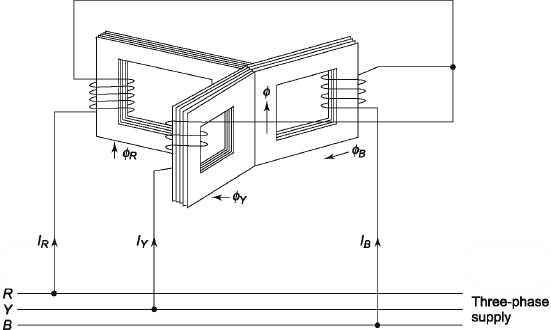
Figure 2.1 Basic Principle of Three-phase Transformers
2.3 CONSTRUCTION OF THREE-PHASE TRANSFORMERS
Three-phase transformers are of the core type and shell type. The three-phase core-type transformer can be made by combining three single-phase core-type transformers. The three-phase shell-type transformer can be made by combining three single-phase shell-type transformers.
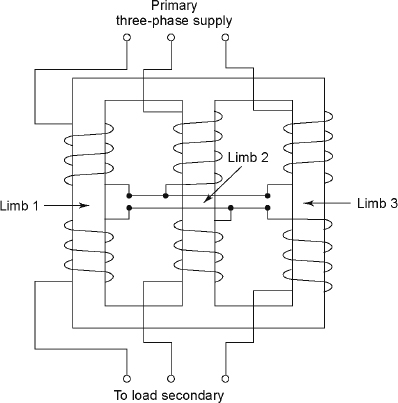
Figure 2.2 Core-type Three-phase Transformer
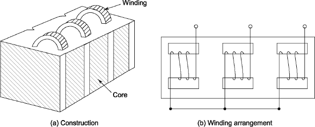
Figure 2.3 Shell-type Three-phase Transformer
2.3.1 Core-type Construction
Figure 2.2 shows a three-phase core-type transformer having a three-limb construction. The core in Figure 2.2 consists of three legs and the magnetic circuit is completed through two yokes, where one is at the top and two are at the bottom. Each limb has primary and secondary windings, which are arranged concentrically. Core-type transformers are usually wound with circular cylindrical coils.
2.3.2 Shell-type Construction
Figure 2.3 shows a three-phase shell-type transformer. In this type, the three phases are more independent than they are in the core-type three-phase transformers because each phase has an individual independent magnetic circuit. The phase magnetic circuits are in parallel. Therefore, these are independent if saturation effects occurring in the common magnetic paths are neglected. The construction and winding arrangements have been shown in Figures 2.3(a) and 2.3(b), respectively. This type of transformers is rarely used.
2.4 THREE-PHASE TRANSFORMER CONNECTION
The primary and secondary windings of three-phase transformers can he connected in several ways such as star and delta, and the voltage can be raised or lowered. The following three-phase transformers are the most commonly used in practice:
- star-star,
- delta-delta,
- star-delta,
- delta-star and
- delta-zig-zag star connection .
2.4.1 Star-Star (γ/γ) Connection
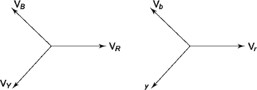
Figure 2.4 shows a star-star connection, which is economical for small, high-voltage transformers because the phase voltage is![]() times the line voltage. Hence, the number of turns per phase and quantity of insulation required is minimum. There is a phase shift of 30° between the phase voltages and line voltages on both primary and secondary, whereas the line voltages on both primary and secondary are in phase with each other, as shown in Figure 2.5.
times the line voltage. Hence, the number of turns per phase and quantity of insulation required is minimum. There is a phase shift of 30° between the phase voltages and line voltages on both primary and secondary, whereas the line voltages on both primary and secondary are in phase with each other, as shown in Figure 2.5.

Figure 2.4 Star-Star Connection
The ratio of voltages on the primary and secondary sides is equal to the transformation ratio of each transformer. The star-star connection works well for balanced load. If the load is unbalanced, the neutral shifts. To prevent this, that star point of the primary is required to be connected to the star point of the generator.
Let VL1 be the line voltage on the primary side. The phase voltage on the primary ( VPh1) is given by the following:
![]()
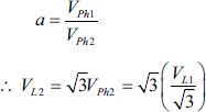
If a is the turns ratio, the phase voltage on the secondary is given the following:
![]()
where ![]()
The suffix ‘1’ indicates the primary, whereas suffix ‘2’ indicates the secondary.
A star-star connection has the following advantages:
- Less number of turns and less quantity of insulation is required because
 .
. - Since IP = IL, the current through the windings is high. The windings must have a large cross-section and must be mechanically strong so that they can bear heavy load and short-circuit.
- There is no phase shift between the primary and secondary voltages.
- It is suitable for the three-phase and four-wire system because of the presence of the neutral point.
A star-star connection has the following disadvantages:
- The neutral point shifts due to unbalanced load and performance is not satisfactory.
- In spite of connecting the neutral point to earth, the third harmonic present in the alternator voltage may appear in secondary and cause distortion of the secondary voltage.
2.4.2 Delta-Delta (Δ/Δ) Connection
Figure 2.6 shows a three-phase transformer having delta connections on both the primary and secondary windings.
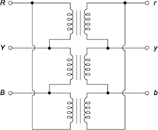
Figure 2.6Delta-Delta Connection
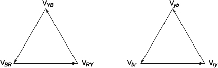
Figure 2.7 shows the phasor diagram of both the primary and secondary sides. From Figure 2.7, it can be seen that there is no phase difference between the primary and secondary voltages. This connection is economical for large, low-voltage transformers because it increases the number of turns per phase.
Let VL1 and VPh1 be the line voltage and phase voltage, respectively, on the primary side, VL2 and VPh2 be the line voltage and phase voltage, respectively, on the primary side, VL2 and VPh2 be the line voltage and phase voltage, respectively, on the secondary side and a be the turns ratio.
For delta connection, VL1 = VPh1 and VL2 = VPh2.
Again,
![]()
A delta-delta connection has the following disadvantages:
- The delta connection provides a closed path for circulation of the third harmonic component of current and hence the flux remains sinusoidal since magnetizing component of current must contain the third harmonic to get the secondary voltage sinusoidal.
- This connection also permits unbalanced loading.
- In the delta-delta connection, if one transformer is inoperative, V-V operation is still possible with reduced rating. (Refer to Section 2.5)
- No distortion in the secondary voltage occurs.
- For delta connection,
 and cross-section of the winding is low, which makes the connection economical for low-voltage transformers.
A delta-delta connection has the following disadvantages:
- It is not suitable for the three-phase four-wire system because the neutral point is absent.
- This connection is generally used for low voltage transformers.
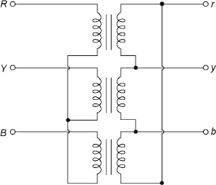
Figure 2.8 Star-Delta Connection
2.4.3 Star-Delta (γ /Δ) Connection
Figure 2.8 shows a three-phase (3-φ) transformer having star and delta connections on the primary and secondary windings respectively.
Figure 2.9 shows the phasor diagram of both the primary and secondary sides. From Figure 2.8, it can be seen that there is a 30° phase difference between the primary and secondary line voltages. The neutral is available on the primary side, and the secondary allows the flow of the third harmonic. The main use of this transformer is to step down voltages and hence it is used at the distribution side, that is, at the receiving end after the transmission.
Let VL1 and VPh1 be the line voltage and phase voltage, respectively, on the primary side, VL2 and VPh2 be the line voltage and phase voltage, respectively, on the secondary side and a be the turns ratio.
For star connection,
![]()
For delta connection,
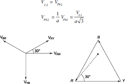
Figure 2.9 Phasor Diagram of Star-Delta Connection
![]()
Since the secondary is connected in delta, this type of transformer is not affected by unbalanced load. A star-delta transformer has the following advantages:
- Since the primary is star connected, fewer numbers of turns are required in the primary, which makes it economical for high-voltage, step-down power transformers.
- The available neutral point on the primary side can be earthed to avoid distortion.
- It is possible to handle large, unbalanced load.
A star-delta transformer has the following disadvantage:
- Since the secondary voltage is not in phase with the primary, it is not possible to make it parallel with star-star and delta-delta transformers.
2.4.4 Delta-Star (Δ/γ) Connection
Figure 2.10 shows a three-phase transformer having delta and star connections on the primary and secondary windings, respectively.
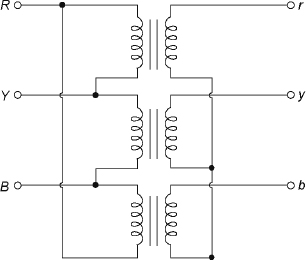
Figure 2.10 Delta-Star Connection
Figure 2.11 shows the phasor diagram of both the primary and secondary sides. From Figure 2.10, it can be seen that there is a 30° phase difference between the primary and secondary line voltages. The neutral point is available on the secondary side. Single phase and three-phase loads can be supplied with this type of transformers. The main use of this transformer is to step up the voltages and hence it is used at the beginning of transmission or at the sending end.
Let VL1 and VPh1 be the line voltage and phase voltage, respectively, on the primary side, VL2 and VPh2 be the line voltage and phase voltage, respectively, on the secondary side and a be the turns ratio.
For a star connection,
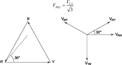
Figure 2.11 Phasor Diagram of Delta-Star Connection
For delta connection, VL1 VPh1
![]()
Again,
Since the secondary is connected in delta, this type of transformers is not affected by unbalanced load.
A delta-star connection has the following advantages:
- Since the primary is delta connected, the winding cross-section is small.
- Since the neutral is available on the secondary side, three-phase and four-wire supply can be carried out.
- No distortion occurs due to the third harmonic component.
- Saving in the cost of insulation is possible due to availability of star connection on one side.
- No difficulty occurs due to large unbalanced load.
A delta-star connection has the following disadvantage:
- Since the secondary voltage is not in phase with the primary, it is not possible to make it parallel with star-star and delta-delta transformers.
2.4.5 Delta-Zig-zag Star Connection
Figure 2.12 shows the two equal halves of each winding on each phase on the star side. To form the star connection each, its phase is formed by using half of the windings from two different phases, as shown in Figure 2.13. Figure 2.14 shows the phasor diagram of this connection. This connection is +30° and its phase-to-phase transformation ratio ![]() and line-to-line transformation ratio
and line-to-line transformation ratio ![]() . This connection is specifically useful for the rotary converters for supplying the three-wire direct current, where the unbalanced DC in the neutral wire will divide in such a way that half of each winding will carry equal direct currents in opposite directions, and hence there will be no resultant unidirectional magnetization of the core due to this unbalanced direct current.
. This connection is specifically useful for the rotary converters for supplying the three-wire direct current, where the unbalanced DC in the neutral wire will divide in such a way that half of each winding will carry equal direct currents in opposite directions, and hence there will be no resultant unidirectional magnetization of the core due to this unbalanced direct current.
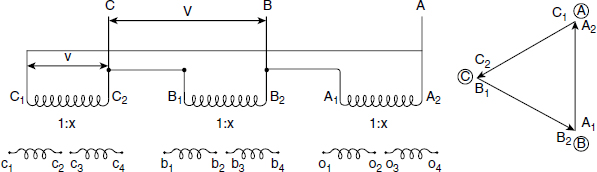
Figure 2.12 Primary Voltage Phasor
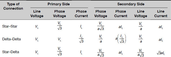
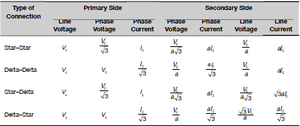
Table 2.1 compares voltage and current relationships for different types of connections.
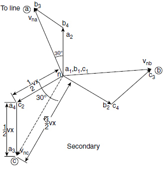
Figure 2.13 Secondary Side Phasor Diagram
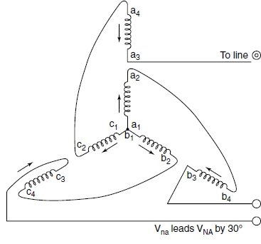
Figure 2.14 Delta-Zig-zag Connection of Transformer with +30° Phase Shift
Table 2.1 Comparison of Voltage and current relationships for different types of connections.
Example 2.1 A three-phase 100 kVA, 5,000/500 V, Y-Y, 50 Hz transformer has an iron loss of 1,500 W. The maximum efficiency occurs at 80 per cent of full load. Calculate
(i) the efficiency of the transformer at full load and 0.85 power factor lagging,
(ii) the efficiency of the transformer at 3/4 th of full load at unity power factor, and
(iii) the maximum efficiency at unity power factor.
Solution
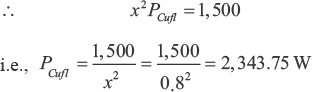
Iron loss = 1,500 W
Since the maximum effi ciency occurs at 80 per cent of full load, x = 0.80.
![]() Cu loss at 80 per cent of full load = 1,500 W
Cu loss at 80 per cent of full load = 1,500 W
Let Cu loss at full load be PCufl W.
(i) Full load:
Total loss = 2,343.75 + 1,500 = 3,843.75 W
Output on full load at 0.85 power factor lagging = 100 × 0.85 × 103 = 85,000 W
![]()
(ii) Cu loss at three-fourths of full load = 0.752 × 2,343. 75 = 1,318.36 W
Total loss = 1,318.36 + 1,500 = 2,818.36 W
Output at three-fourths of full load at unity power factor = (3/4) × 100 × 10 3 = 75,000 W
![]()
(iii) During the maximum efficiency, total loss = 2 × 1,500 = 3,000 W
Output = 100 × 0.8 × 1 × 10 3 = 80,000 W
![]()
2.5 OPEN-DELTA OR V-V CONNECTION
If one of the transformers of delta-delta connection is inoperative while a three-phase supply is connected to primary, three equal supplies will be available at the secondary terminals on no load and supply is still possible with reduced capacity. This method is known as open-delta or V-V connection. It has the following applications:
- If one of the transformers in delta-delta bank is inoperative, it is possible to continue service with reduced capacity.
- If the three-phase load is small, it is preferable to use a V-V connection.
- If the load increases, in future, the open delta can be closed to increase the rating.
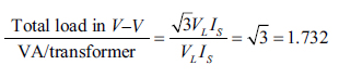
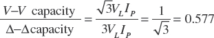
Figure 2.15 shows the open-delta or V-V bank. The total load carried by the V-V bank is not two-thirds of the full load. It is only 57.7 per cent of full load and thus there is reduction of 15.5 per cent. Let there be delta-delta bank of three 15 kVA transformers. If it operates in V-V, the capacity of the V-V bank is (15 + 15) × 0.866, that is, 25.98 kVA instead of (15 + 15) kVA or 30 kVA. We can prove that the ratio of V-V capacity to delta-delta capacity is 57.7 per cent instead of 66.66 per cent.
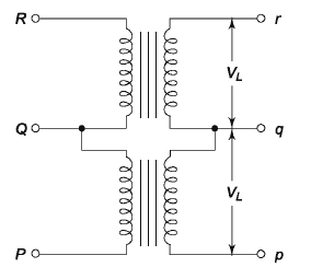
We can write,
![]()
To get V-V bank, one transformer of Δ-Δ bank must be open; that is, secondary line current = secondary phase current or, IL=IP.
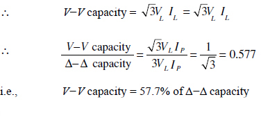
![]() V-V bank carries 57.7 per cent of original load. Now, we can conclude the following during V -V operation:
V-V bank carries 57.7 per cent of original load. Now, we can conclude the following during V -V operation:
- The bank capacity becomes 25.98 kVA instead of 30 kVA.
- Since 30 × 0.866 = 25.98, we can say that 86.6 per cent of rated capacity of two working transformers is available. This factor is also known as utility factor.
- Each transformer supplies 57.7 per cent of load instead of 50 per cent during V-V operation. If the rated load is supplied by Δ-Δ bank and one transformer is removed, the overload on each of the two transformers becomes 73.2 per cent. This is because
In the V-V bank the average power factor is less than that of the load and the secondary terminal voltages become unbalanced with increase of load. Some provision should be made to reduce this overload to avoid overheating and consequent breakdown of two transformers. This overload may be carried temporarily.
If the V-V bank supplies power to a balanced three-phase load having power factor cos β, one transformer will operate at power factor cos (30°-β) and the other at cos (30° +β). Hence, the two transformers will have different voltage regulation.
The power supplied by the two transformers are the following:
![]()
The following conclusions can be drawn:
- β = 0° The power factor of each transformer is 0.866.
- β = 30° In this case the power factor of one transformer is cos (30° - 30°), that is, 1, and the power factor of the other transformer is cos (30° + 30°), that is, 0.866.
- β = 60° In this case the power factor of one transformer is cos (30° - 60°), that is, 0.866, and the power factor of the other transformer is cos (30° + 60°), that is, 0. Therefore, one transformer will not supply any load and the entire load is carried out by the other transformer.
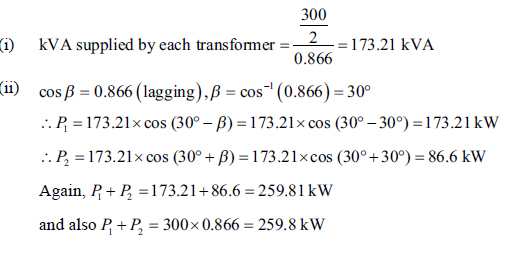
Example 2.2 Two transformers are connected in open-delta supply with a 300 kVA balanced load operating at 0.866 power factor lagging. If the load voltage is 440 V, calculate the following:
(i) kVA supplied by each transformer and
(ii) kW supplied by each transformer.
Solution
2.6 SCOTT CONNECTION OR T-T CONNECTION
Figure 2.16 shows a Scott connection or T-T connection, which was originally proposed by Charles F. Scott. This connection needs two transformers on each side instead of three transformers and accomplishes three-phase to three-phase transformations. The transformer, which is a horizontal member of the connection having centre taps both on the primary and the secondary, is known as the main transformer. The other transformer of the primary and secondary whose one end is connected to the main transformer has a 0.866 tap and it is called the teaser transformer. Three-phase supply is given to the other end of the teaser and the two ends of the main transformer.
Figure 2.17 shows the voltage diagram of the primary and secondary where the three-phase supply voltage is 100 V. The turns ratio ( a) is taken as unity.
From Figure 2.17, we have ESR = ESQ = 50 V, having a phase difference of 180° as SR and SQ are on the same coils. The value of ![]() which lags behind the voltage across the main by an angle of 90°. Similar relations also occurs for the secondary.
which lags behind the voltage across the main by an angle of 90°. Similar relations also occurs for the secondary.
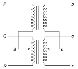
From Figure 2.17(b), for a load power factor of unity ISQ lags behind ESQ by an angle 30° whereas ISR leads ESR by an angle 30°. Therefore, we can conclude that each half of the main transformer will operate at different power factors. The teaser transformer operates at 0.866 of its rated voltage, and the main transformer operates at 0.866 power factor. Therefore, the coils of the main transformer work at 86.6 per cent of its kVA rating. The rating ratio of Scott connection is the same as that of V-V connection if and only if two identical coils are used while heating in the two cases is different.

Figure 2.17 Voltage and Phasor Diagram of T-T Connection
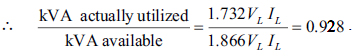
In this case, the available VA capacity is = VLIL + 0.866 VL IL = 1.866 VL IL. IL is the primary line current. Actually utilized VA due to three-phase supply = 1.732 VLIL.
 Hence, this connection is more economical compared to V-V connection. For teaser transformer with load of unity power factor at the secondary, we can conclude the following from Figure 2.18:
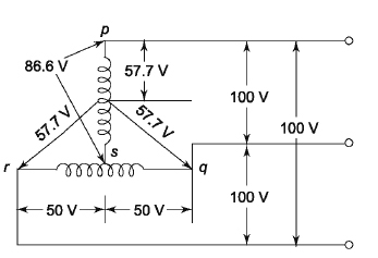
Figure 2.18 Phasor Diagram at Unity Power Load at Secondary
(i) The neutral is one-third way up from S.
(ii) The current in the teaser transformer is in phase with its voltage.
(iii) The current in one half of the main transformer leads the voltage, whereas the current in the other half lags the voltage.
Another important point is that for a balanced load of power factor cos β, the current in one half leads the voltage by an angle cos (30° - β), whereas the current in other half lags the voltage by an angle cos (30° + β), which is similar to the V-V connection. The Scott connection can also be used for conversion of three phases to two phases.
2.7 THREE-PHASE TO TWO-PHASE CONVERSION
To convert three phases to two phases or vice versa, the connection shown in Figure 2.19(a) is used, which is nothing but a Scott connection having two transformers of different ratings. If both the transformers are identical, they should have suitable tappings.
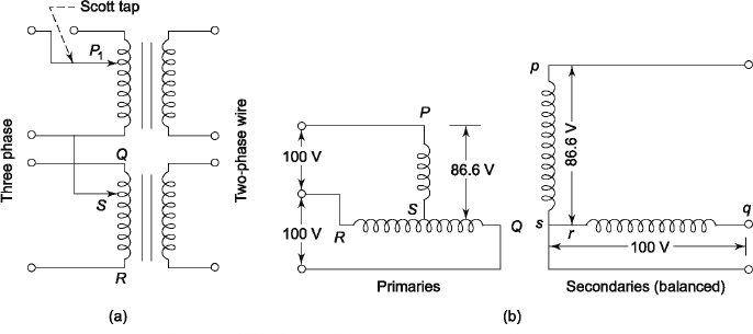
Figure 2.19 Three-phase to Two-phase Conversion
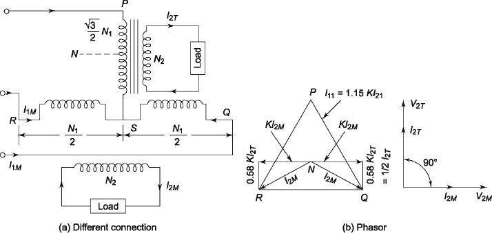
Figure 2.20 A Different Connection and a Phasor
The points s and r of the secondary are connected as shown in Figure 2.19(b), which gives the two-phase three-wire system. Here, Esp = 86.6 V whereas Esq = 100 V, producing two unequal voltages. To get the same volt/turn both in the primary and the secondary, one line of three-phase supply is connected to point P1, where SP1 is 86.6 per cent of the teaser primary turns. The secondary voltages will be equal in magnitude if and only if the secondary transformers have the same number of turns, which results in a symmetrical two-phase three-wire system instead of an unsymmetrical two-phase three-wire system.
Figure 2.20(a) shows a different connection where the primary has N1 number of turns and is connected between Q and R of the main transformer. Now, VPQ = VQR = VRS = V1 if the supply line voltage is V1 and ![]() The number of turns between P and S is
The number of turns between P and S is ![]() to give the same volt/turn in both primaries. The secondary terminal voltages will be equal in magnitude if the secondaries have an equal number of turns. But the secondary terminal voltages will be quadrature to each other. Since
to give the same volt/turn in both primaries. The secondary terminal voltages will be equal in magnitude if the secondaries have an equal number of turns. But the secondary terminal voltages will be quadrature to each other. Since ![]() and it is not equal to
and it is not equal to ![]() is not the neutral point. To get the position of the neutral point, let us take N as the neutral point. N will be the neutral point only if
is not the neutral point. To get the position of the neutral point, let us take N as the neutral point. N will be the neutral point only if ![]() . Now
. Now ![]() . This means that N is above S by a number of turns equal to 28.8 per cent of N1. N divides the teaser winding in the ratio of 2:1 because
. This means that N is above S by a number of turns equal to 28.8 per cent of N1. N divides the teaser winding in the ratio of 2:1 because ![]()
Let the current supplied by the teaser secondary be I2T at unity power factor. The teaser primary current becomes 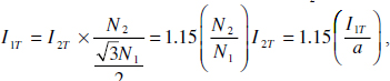 , where
 ![]() is the turns ratio.
is the turns ratio.
The current IM1 of each half of the main transformer of the primary has the following two components:
(i) One part is required to balance the secondary current (I2M), which is ![]()
(ii) The other part is equal to one half of the teaser primary current or (1/2) I1T because the main transformer primary serves as the return path for teaser primary current and it divides itself into two halves at the mid point S.
The condition due to a balanced two-phase load at a lagging power factor of 0.866 has been shown in Figure 2.21(a). The three-phase side is balanced here. The main transformer rating is 15 per cent greater than the rating of the teaser transformer. This is because its voltage is 15 per cent greater. But its current remains the same.
Figure 2.21(b) shows the condition due to an unbalanced two-phase load having different currents and power factors.
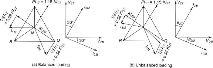
Figure 2.21 Vector Diagram for Balanced and Unbalanced Loading
Example 2.3 Two T-connected transformers are used to supply a 440 V, 4.4 kVA balanced load to form a balanced three-phase supply of 4.4 kV. Determine (i) voltage and current rating of each coil and (ii) kVA rating of the main and teaser transformers.
Solution
(i) The voltage across main primary = 4.4 kV = 4,400 V and that across teaser primary = 0.866 × 4,400 = 3,810.4 V. The current is the same in the teaser and main primary and it is equal
to the line current. 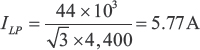
The secondary teaser voltage = 440 × 0.866 = 381 V
The secondary main voltage = 440 V
The secondary line current (ILS) = (ILP × 4,400)/440 = 5.77 × 10 = 57.7 A
(ii) Main kVA = 4,400 × 5.77 × 10-3 = 25.388 kVA
Teaser kVA = 0.866 × main kVA = 0.866 × 25.388 = 21.986 kVA
Example 2.4 Two single-phase transformers working at 200 V are supplied from 2,200 V, three phase mains through a Scott connection. Find the current in each line of the three-phase mains when the power taken by each furnace is 450 kW at a power factor of 0.85 lagging. The losses in the transformer are negligible.
Solution
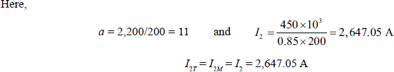
Since the two-phase load is balanced, the three-phase side is also balanced.
Primary currents are = (1.15)I2/a = (1.15 × 2,647.05)/11 = 276.74 A
Again, for star connection, phase current and line current are equal.
![]() line current = 276.74 A
line current = 276.74 A
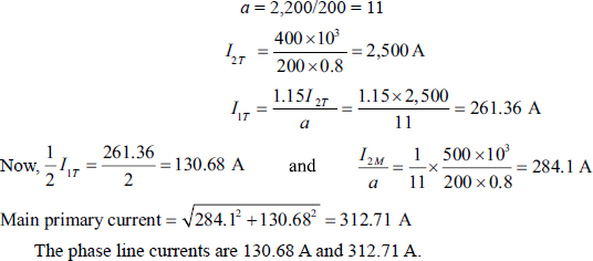
Example 2.5 In a Scott connection, the loads on the two-phase side are 400 kW and 500 kW, both at 200 V and 0.8 power factor lagging. The three-phase line voltage is 2,200 V. The 400 kW load is on the leading phase on the two-phase side. Neglecting transformer losses, calculate the value of line currents on the three-phase side.
Solution
2.8 PARALLEL OPERATIONS OF TRANSFORMERS
For parallel operation of three-phase transformers, the conditions for paralleling single-phase transformers are required as well as the following additional conditions:
- The ratio of voltage should refer to terminal voltage of the primary and secondary.
- The phase sequence must be identical.
- The phase between the primary and secondary of all transformers to be paralleled must be identical.
2.9 THREE-PHASE TO SIX-PHASE CONVERSION
The following are commonly used schemes for three-phase to six-phase conversion:
(i) double-star connection,
(ii) double-delta connection,
(iii) six-phase star connection and
(iv) diametrical connection
2.9.1 Double-star Connection
Figure 2.22 shows a double-star connection of transformers for three-phase to six-phase conversion, where three identical single-phase transformers are used. The three primaries are connected in delta, whereas each transformer in the secondary unit splits into two equal connections. Each set of secondaries is connected in star.
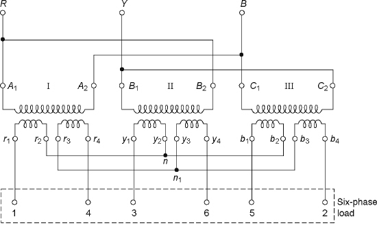
Figure 2.22 Double-Star Connection
2.9.2 Double-delta Connection
Figure 2.23 shows the double-delta connection of transformers for three-phase to six-phase conversion, where three identical single-phase transformers are used. The three primaries are connected in delta, whereas each transformer in the secondary unit splits into two equal connections. Each set of secondaries is connected in delta.
2.9.3 Six-phase Star Connection
Figure 2.24 shows the six-phase star connection of transformers for three-phase to six-phase conversion, where three identical single-phase transformers are used. The three primaries are connected in delta and the centre tap of each secondary transformer is connected to neutral.
2.9.4 Diametrical Connection
Figure 2.25 shows a diametrical connection. No centre tapping is used here. Neutral connections are not required.
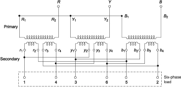
Figure 2.23 Double-delta Connection
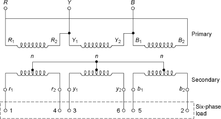
Figure 2.24 Six-phase Star Connection
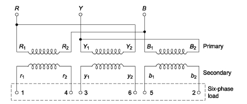
Figure 2.25 Diametrical Connection
2.10 THREE-WINDING TRANSFORMER
In addition to the primary and secondary windings in a transformer, there may be a third winding known as tertiary winding, which has the low-voltage rating whereas the primary has the highest voltage rating. The kVA ratings in three-phase transformers are unequal, whereas it is equal in two-winding transformers. The chief advantage of tertiary winding is that it reduces imbalance of the primary and secondary and hence the secondary load imbalance is distributed more evenly among the primary phases. This is because when the primaries and secondaries are star connected and the load is unbalanced, this reflects in unbalanced primary currents and the increased circulating current is reduced in tertiary windings. Figure 2.26 shows schematic diagram of a three-winding transformer having the primary (N1), secondary (N2) and tertiary windings (N3).
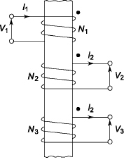
Figure 2.26 Three-winding Transformer
From Figure 2.26, we can have for an ideal transformer
![]()
Tertiary windings have the following advantages:
- It is possible to supply substation auxiliaries at different voltage with respect to the primary and secondary with the help of tertiary windings.
- To inject the reactive power into the system, synchronous capacitors are connected across the delta-connected output of the tertiary windings
- It is possible to interconnect three-phase supply systems with the help of tertiary windings.
- The impedance offered to the zero-sequence current by the delta connected tertiary is reduced and hence the sufficient earth-fault current can flow, which helps the proper operation of the protective devices.
- Since continuity of supply is more important, it is possible to give the supply of single load from two sources.
- It possible to measure voltage for high-voltage testing transformers with the help of tertiary windings.
Currently, tertiary winding transformers are manufactured having tertiary winding voltage ratings up to 35 per cent of the total transformer VA rating. If both sets of the windings are connected in delta, the imbalance and the third harmonic do not come into picture.
2.11 THREE-PHASE TRANSFORMER CONNECTIONS
The twelve standard methods have been illustrated in Table 2.2. The four main groups are given as follows:
Group 1: Zero phase displacement (Y y0, Dd0, Dz0)
Group 2: 180° phase displacement (Y y6, Dd6, Dz6)
Group 3: 30° lag phase displacement (D y1, Yd 1, Yz1)
Group 4: 30° lead phase displacement ( D y 11, Yd11, Y z11)
Table 2.2 Different Types of Three-phase Transformer Connections
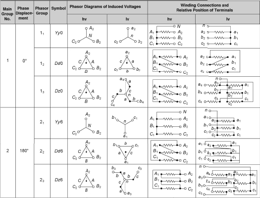
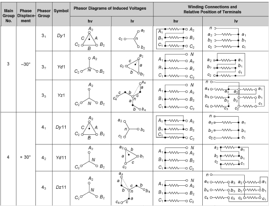
The delta-star connection (4, dy11) is the most popular method of connecting transformers. Here, the lettering for phase is taken as A, B and C for primary, that is, the hv side, and a, b and c for the lv side or secondary.
2.12 RATING OF TRANSFORMERS
The broad specifications of transformers are given as follows:
- kVA rating.
- Rated voltage.
- Number of phases (i.e. one phase or three phases).
- Rated frequency.
- Type of connections for three phases.
- Tappings if it exists.
- Type of core.
- Power or distribution type.
- Ambient temperature (it is generally 40°C).
- Nature of cooling.
- Rise of temperature above ambient temperature.
- Voltage regulation.
- No-load current.
- Efficiency.
The standard ratings of distribution transformers are 16, 25, 40, 50, 63, 80 and 100 kVA, whereas the standard ratings of power transformers are 25, 40, 63, 100, 125, 160, 200, 250, 315, 400, 500, 630, 800, 1,000, 1,250, 1,600, 2,000, 2,500, 3,125, 4,000, 6,300, 8,000, 10,000, 12,500, 160,000, 20,000, 25,000, 31,500, 40,000, 50,000, 63,000 and 80,000 kVA.
ADDITIONAL SOLVED PROBLEMS
Example 2.6 A three-phase step-down transformer having turns ratio per phase of 10 takes 10 A when connected to 3.3 kV supply mains. Determine the secondary line voltage, line current and output when the transformer windings are connected in (i) star/delta and (ii) delta/star.
Solution
Example 2.7 A three-phase, 1,200 kVA, 6.6/1.1 kV transformer has delta-connected primary and star-connected secondary. The per phase values of the primary resistance and secondary reactance are 2 Ω and 0.03 Ω respectively. Calculate the efficiency on full load at 0.9 power factor lagging if iron loss is 20 kW.
Solution

Example 2.8 A 1,500 kVA, 6.6/1.1 kV, three-phase delta-star-connected transformer has the following test result: SC test (instruments placed on the hv side) = 300 V, 131.21 A and 30 kW. Calculate its percentage resistance, percentage reactance drops, percentage regulation and percentage efficiency on full load at 0.8 power factor lagging. The iron loss during OC test is 25 kW.
Solution
From SC test data:
Primary voltage per phase = primary line voltage = 300 V
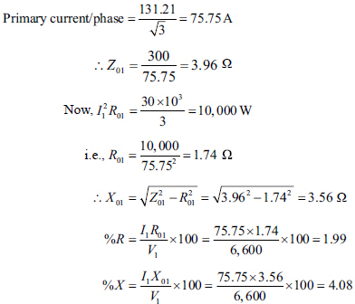
The percentage voltage regulation on full load at 0.8 power factor lagging = vr cosβ + v x sinβ = 1.99 × 0.8 + 4.08 × 0.6 = 4.04
![]()
Therefore, short circuit test has been carried out on full-load conditions.
Total losses = 30 + 25 = 55 kW
Full-load output = 1,500 × 0.8 = 1,200 kW
![]()
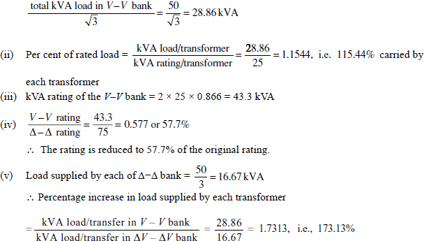
Example 2.9 A three-phase Δ-Δ bank consists of three 25 kVA, 3,300/300 V transformers and supplies a load of 50 kVA. After removing one transformer, determine the following for V-V connection:
(i) kVA load carried by each transformer .
(ii) per cent of rated load carried by each transformer .
(iii) total kVA rating.
(iv) ratio of V-V bank to Δ-Δ bank transformer ratings.
(v) percentage increase in load on each transformer when the bank is converted into V-V connection.
Solution
(i) kVA load supplied by each of the two transformers
SIGNIFICANT POINTS
Advantages of Three-phase Transformers
A single three-phase transformer bank has the following advantages:
- It occupies less space for the same rating, compared to a bank of three single-phase transformers.
- It weighs less.
- The cost is also less.
- Since only one unit is required to be handled, it is easy to operate.
- It can be transported very easily.
Comparison of Voltage and Current Relationships for Different Types of Connections
- The core is of a smaller size and hence less material is required.
The power supplied by the two transformers is as follows:

- β = 0°
The power factor of each transformer is 0.866.
- β = 30°
In this case the power factor of one transformer is cos (30° – 30°), i.e., 1, and the power factor of the other transformer is cos (30° + 30°), i.e., 0.5.
- β = 60°
In this case the power factor of one transformer is cos (30° – 60°), i.e., 0.866, and the power factor of the other transformer is cos (30° + 60°), i.e., 0.
 One transformer will not supply any load and the entire load is carried out by the other transformer.
For Scott connection:
![]()
SHORT QUESTIONS AND ANSWERS
Q.1 State the different forms of connections used in three-phase transformers.
Ans. The following are the possible connections:
(i) star-star,
(ii) star-delta,
(iii) delta-delta,
(iv) delta-star and
(v) open-delta
Q.2 Where is the delta-delta connection applied?
Ans. It is applied in large low-voltage transformers where insulation problem is less urgent.
Q.3 Where is the star-star connection applied?
Ans. It is best suited for small high-voltage transformers with balanced load.
Q.4 Where is the star-delta connection applied?
Ans. It is applied at the sending end of transmission lines to step up the voltage.
Q.5 Where is the delta-star connection applied?
Ans. It is used as a step-down transformer to provide three-phase four-wire supply.
Q.6 Where is the open-delta connection applied?
Ans. When two three-phase loads are too small or one transformer in Δ-Δ bank is disabled, then the open-delta connection is applied.
Q.7 Where is the Scott connection applied?
Ans. It is applied to supply three-phase voltage from a two-phase source or vice versa.
Q.8 What do you mean by phasing out of a three-phase transformer?
Ans. Phasing out detects the same phase terminals of the primary and secondary.
SUPPLEMENTARY PROBLEMS
1. A three-phase transformer, 33/6.6 kV, Δ - Y, 2 MVA, has a primary resistance of 8 Ω per phase and a secondary resistance of 0.08 Ω per phase. The percentage impedance is 7 per cent. Find the secondary voltage with rated primary voltage and hence the regulation for full load at 0.75 power factor lagging conditions.
[Ans. 5.25%]
2. A three-phase transformer rated at 1,000 kVA, 11/3.3 kV, has its primary windings star-connected and its secondary windings delta-connected. The actual resistances per phase of these windings are as follows: R1 = 0.375 Ω, R2 = 0.095 Ω, X1 = 9.5 Ω and X2 = 2 Ω per phase. Calculate the voltage at normal frequency which must be applied to primary terminals in order to obtain full-load current in the windings when the secondary terminals are short circuited. Also, calculate the power input under these conditions.
[Ans. 1.54 kV, 6 kW]
3. The maximum efficiency of a three-phase, 11,000/400 V, 500 kVA transformer is 98.8 per cent and occurs at 80 per cent of full load at unity power factor. Its percentage impedance is 4.5 per cent. Load power factor is now varied, while the load current and the supply voltage are held constant at their rated values. Determine the load power factor at which the secondary terminal voltage is minimum.
[Ans. 0.1687 (lagging)]
4. A 2000 kVA, 6,600/400 V, three-phase is delta connected on the hv side and store connected on the lv side. Determine its percentage reactance and percentage reactance drops, percentage efficiency and percentage regulation at full-load 0.8 power factor leading. The following data are given:
SC test: 400 V, 175 A, 17 kW
OC test: 400 V, 150 A, 15 kW
[Ans. 0.85%, 6%, 98.04%, -2.92%]
5. Two transformers connected in open delta supply a 400 kVA balanced load operating at 0.866 power factor lagging. The load voltage is 440 V. What is the (i) kVA supplied and (ii) kW supplied by each transformer?
[Ans. (i) 231 kVA, (ii) 231 kW, 115.5 kW]
6. The primary and secondary windings of two transformers, each rated 250 kVA, 11/2 kV and 50 Hz, are connected in open delta. Find (i) the kVA load that can be supplied from this connection and (ii) currents on the hv side if a delta-connected three-phase load of 250 kVA, 0.8 power factor lagging, 2 kV, is connected to the lv side of the connection.
[Ans. (i) 433 kVA, (ii) 13 A]
7. Two T- connected transformers are used to supply a balanced load of 100 kVA at 400 V from a balanced 11 kV three-phase supply. Determine (i) current and voltage rating of each transformer coil and (ii) kVA rating of the main and teaser transformers.
[Ans. (i) 11,000 V, 9,526 V, 5.25 A, 400 V, 346.4 V, 144.34 A (ii) 57.75 kVA, 50 kVA]
8. A balanced three-phase 100 kW load at 400 V and 0.8 power factor lagging is to be obtained from a balanced two-phase 1,100 V lines. Determine the kVA rating of each unit of the Scott-connected transformer.
[Ans. 72.172 kVA, 62.5 kVA]
9. It is desired to transform 2,400 V, 500 kVA three-phase power to two-phase power at 600 V by Scott-connected transformers. Determine the voltage and current ratings of both primary and secondary of each transformer. Neglect the transformer´s no-load currents.
[Ans. Teaser: 2,080 V, 1,200 A (primary); 600 V, 4,167 A (secondary); Main: 2,400 V, 1,200 A (primary); 600 V, 4,167 A (secondary) ]
MULTIPLE-CHOICE QUESTIONS AND ANSWERS
1. A three-phase transformer over a bank of three single-phase transformers of equal rating has the advantages of
(a) low cost
(b) less weight
(c) occupation of less space
(d) all of the above
2. Two three-limb, three-phase delta-star-connected transformers are supplied from the same source. One of the transformers is Dy1 and the other is Dy11 connection. The phase difference of the corresponding phase voltage of the secondaries would be
(a) 0°
(b) 30°
(c) 60°
(d) 120°
3. Three single-phase transformers are connected to form a three-phase transformer bank. The transformers are connected as shown in Figure 1. The nomenclature of the above connection for phase sequence ABC is
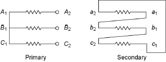
Figure 1
(a) Yd 0
(b) Yd 6
(c) Yd 11
(d) Yd 1
4. Which of the following connections of the transformer will give the highest secondary voltage?
(a) delta primary, delta secondary
(b) delta primary, star secondary
(c) star primary, star secondary
(d) star primary, delta secondary
5. A three-phase transformer has its primary connected in delta and secondary in star. Secondary to primary turn ratio per phase is 5. For a primary voltage of 400 V, the secondary voltage would be
(a) 2,000 V
(b) 80 V
(c) 3,464 V
(d)80![]() V
V
6. In a properly connected Y - Δ transformer, a voltmeter connected is in the secondary (opening a node of delta); the voltmeter will read
(a) zero voltage
(b) line voltage of supply
(c) phase voltage in the secondary
(d) none of the above
7. In a Δ-Δ connection, if one transformer becomes disabled, the capacity will reduce to
(a) 66.67%
(b) 50%
(c) 40%
(d) 57.74%
Answers
1 (d) 2 (c) 3 (d) 4 (d) 5 (c) 6 (a) 7 (d)