
Chapter 4
Working with Infrared
IN THIS CHAPTER
![]() Looking at ways to transmit information using infrared light
Looking at ways to transmit information using infrared light
![]() Creating infrared light
Creating infrared light
![]() Detecting infrared light
Detecting infrared light
![]() Building a proximity detector
Building a proximity detector
In this chapter, you learn how to work with circuits that detect the invisible light that’s commonly called infrared. Infrared light has all sorts of applications for wireless communication, the most common of which is the remote control for your television. Other uses for infrared include night-vision goggles and cameras, and temperature detection.
Have fun!
Introducing Infrared Light
Infrared light is light whose frequency is just below the range of visible red light. Specifically, infrared is light whose frequency falls between 1 THz to 400 THz (one THz is one trillion cycles per second). The infrared spectrum falls right between microwaves and visible light.
Remember from Chapter 1 of this minibook that there’s an inverse relationship between frequency and wavelength. In other words, the lower the frequency, the longer the wavelength. If you describe infrared in terms of its wavelength rather than its frequency, infrared waves are longer than the waves of visible light, but shorter than microwaves. The wavelength of infrared light is between 0.75 to 300 micrometers, which is a millionth of a meter. Thus, at the very bottom edge of the infrared spectrum, the infrared waves are about one-third of a millimeter long. At the upper end, the waves are about one thousandth of a millimeter long. If the waves get any shorter than that, they become visible light.
Figure 4-1 shows the entire spectrum of electromagnetic radiation, so you can see where infrared falls within the grand scheme of things radiation-wise.

FIGURE 4-1: Infrared light falls between visible light and microwaves.
Infrared light isn’t visible to human eyes. I guess Mother Nature decided that we didn’t need to be looking at things in infrared. It’s too bad because more than half of all the light energy emitted from our sun is in the form of infrared light. If our eyes could see infrared light as well as the visible light we can see, a sunny day would seem twice as bright.
 Sometimes infrared light is confused with heat. That’s because we can’t see infrared light waves, but we can feel them in the form of heat. In other words, infrared light waves heat surfaces that absorb them. Visible light does this too. That’s why it’s cooler in the shade than it is in the sun. Because heat is an effect of infrared light, infrared light can be used as a heat source. But infrared light and heat aren’t the same thing.
Infrared light is often used to detect objects that we can’t see in visible light. One common application of this is night vision. According to a principal of physics called Planck’s law, all matter emits electromagnetic radiation if its temperature is above absolute zero. Some of that radiation is in the infrared spectrum, so devices that can detect infrared light can literally see in the dark.
To enhance the effect, some night-vision devices actually illuminate an area with infrared light. Because the human eye can’t see the infrared light, the area illuminated still appears dark to us, but to a detector sensitive to infrared light, the area is lit up and fully visible.
Another common application of infrared light is for wireless communications across short distances. The best known infrared devices are television remote controls. The remote control unit contains a bright infrared light source, and the television itself includes an infrared detector. When you point the remote control at the television and push a button, the remote control turns on the infrared light source and encodes a message on it. The receiver picks up this signal, decodes the message, and does whatever the message directs it to do — turns up the volume, changes the channel, and so on.
Like visible light, infrared light can be blocked by solid objects and it can bounce off of reflective objects. That’s why the remote won’t work if your spouse is standing between you and the television. But it’s also why you can get around your spouse by pointing the remote at a window. The infrared waves bounce off the glass and, if the angle is right, arrive at the television.
The first wireless remote control was developed by Zenith in 1955. It used ordinary visible light, could turn the TV on or off, and could change channels. It had one nasty defect: You had to position your television in the room so that light from an outside source (such as the setting sun shining through a window) didn’t hit the light sensor. Otherwise, the TV might shut itself off right in the middle of the evening news when the sun reached just the right angle and hit the sensor.
Remotes today use complicated encoding schemes to avoid such random misfirings. You’re probably familiar with the procedure you must go through when programming a remote control to work with a particular television. This programming is necessary because there’s no widely accepted standard for how the codes on a remote control should work, so each manufacturer uses its own encoding scheme.
Detecting Infrared Light
There are several ways to detect infrared light in an electronic circuit, but the most common is with a device called a phototransistor. You can buy a phototransistor for a few bucks at RadioShack or any other store that stocks electronic components.
To understand how a phototransistor works, first review how a transistor works. A transistor has three terminals, known as the base, collector, and emitter. Within the transistor, there’s a path between the collector and emitter. How well this path conducts depends on whether voltage is applied across the base and the emitter. If voltage is applied, the collector-emitter path conducts well. If there’s no voltage on the base, the collector-emitter path doesn’t conduct.
In a phototransistor, the base isn’t a separate terminal that’s connected to a voltage source in your circuit. Instead, the base is exposed to light. When infrared light hits the base, the energy in the light is converted to voltage, and the emitter-collector path conducts.
Thus, infrared light hitting the base has the same effect as voltage on the base of a traditional transistor: The infrared light turns the transistor on. The brighter the infrared light, the better the emitter-collector path conducts.
Figure 4-2 shows a simple circuit that uses an IR phototransistor to detect infrared light. When infrared light is present, the collector-emitter circuit conducts, and the LED lights up. Thus, the LED lights when the phototransistor is exposed to infrared light.

FIGURE 4-2: A simple infrared detector circuit.
Project 25 shows you how to build this circuit on a solderless breadboard, and Figure 4-3 shows the assembled circuit.

FIGURE 4-3: The assembled infrared detector circuit (Project 25).
Once you have assembled this circuit, try exposing the phototransistor to different light sources to see whether they emit infrared light. One sure source of infrared is a TV remote control. Point the remote at the phototransistor and press any button on the remote. You should see the LED flash on and off quickly as it responds to the infrared signals being sent by the remote.
Another interesting source of infrared is an open flame. Be very careful, of course; I don’t want you burning down your house just to see if the flames produce infrared light. If you have a small gas lighter, light it up and hold it near the phototransistor.
Project 25: A Simple IR Detector
In this project, you build a simple infrared light detector using a phototransistor. When the phototransistor is exposed to infrared light, the LED lights up.


Parts
- One 9 V battery snap holder (RadioShack 2700325)
- One 9 V battery
- One IR phototransistor (RadioShack 2760145)
- One red LED (RadioShack 2760209)
- One
 W resistor (orange-orange-brown)
Steps
Throughout these steps, use the negative (–) bus strip on the left side of the board for ground and the positive (+) bus strip on the right side of the board as the positive voltage.
-
Insert the phototransistor.
Insert the phototransistor as follows:
Collector (Long)
Emitter (Short)
Positive bus
J5
-
Insert the resistor.
Insert the resistor as follows:
From
To
C5
H5
-
Insert the LED.
Insert the LED as follows:
Cathode (Short)
Anode (Long)
Ground bus
A5
-
Connect the battery.
Insert the red lead to the positive bus and the black lead to the negative bus.
-
Expose the phototransistor to an infrared light source.
Try a variety of sources, including a TV remote control, a flame (be careful!), and sunlight. Also, try other sources that don’t emit infrared, such as an LED flashlight.
Creating Infrared Light
The easiest way to create infrared light is by using a special light-emitting diode (LED) that operates in the infrared spectrum. Infrared LEDs (often called IR LEDs) are readily available at RadioShack or any other store that sells electronic parts.
IR LEDs are similar to regular LEDs, except that you can’t see the light they emit. The LED itself is usually a dark purple or blue color. Like other LEDs, the cathode lead is shorter than the anode lead.
As with any LED, you must use a resistor in series with an IR LED to prevent excess current from burning out the LED. To calculate the size of the resistor, you need to know three things:
- The supply voltage: For example, 9 V.
- The LED forward-voltage drop: For most infrared LEDs, the forward-voltage drop is 1.3 V.
- The desired current through the LED: Usually, the current flowing through the IR LED should be kept under 50 mA. However, IR LEDs are typically rated for more current than regular LEDs. The ones I buy from RadioShack can handle up to 150 mA.
With these three facts in hand, you can calculate the correct resistor size by using Ohm’s law:
-
Calculate the resistor voltage drop.
To do that, subtract the voltage drop of the IR LED (typically 1.3 V) from the total supply voltage. For example, if the total supply voltage is 9 V and the LED drops 1.3 V, the voltage drop for the resistor is 7.7 V.
-
Convert the desired current to amperes.
In Ohm’s law, the current must be expressed in amperes. You can convert milliamperes to amperes by dividing the milliamperes by 1,000. Thus, if your desired current through the IR LED is 50 mA, you must use 0.05 A in your Ohm’s law calculation.
-
Divide the resistor voltage drop by the current in amperes.
This gives you the desired resistance in ohms. For example, if the resistor voltage drop is 7.6 V and the desired current is 50 mA, you need a
 resistor.
 -
Choose a standard resistor size that’s close to the calculated resistance.
A
 resistor is close enough for a 9 V circuit. If you don’t have a
  resistor, a
  or
or  will do the job.
Once you’ve chosen the correct resistor size, just wire it in series with the IR LED, as shown in the schematic in Figure 4-4.

FIGURE 4-4: Use a current-limiting resistor to protect an IR LED.
Building a Proximity Detector
The combination of an IR LED and a photodiode is often used as a proximity detector, a gadget that detects when an object is nearby. There are two ways to build a proximity detector. One is to mount the IR LED and the phototransistor so that they face each other. Then, the infrared light from the IR LED is detected by the phototransistor. If an object comes between the IR LED and the phototransistor, the light is blocked, and the phototransistor turns off.
The other way to build a proximity detector is to mount the IR LED and the IR photodiode next to each other facing the same direction. When an object comes near the IR LED, some infrared light will bounce off the object and be detected by the phototransistor.
You can learn how to build two types of proximity detector circuits in the next two sections of this chapter.
Building a Common-Emitter Proximity Detector
A schematic for a simple proximity circuit is shown in Figure 4-5. Although it isn’t shown in the schematic, this circuit assumes that IR LED and Q1 are oriented so that Q1 can detect the infrared light emitted by IR LED, either indirectly (for a proximity detector) or directly (for an interrupter).

FIGURE 4-5: A common-emitter proximity detector circuit.
This circuit is called a common-emitter circuit because the phototransistor’s emitter is common between the phototransistor side of the circuit and the output side of the circuit that’s connected to the IR LED. In a common-emitter circuit, the output voltage is on when infrared light is detected by the phototransistor. Thus, the red LED lights up when the path between the IR LED and phototransistor isn’t obstructed. If you block the path between the IR LED and phototransistor, the red LED goes dark.
Project 26 shows how to build this circuit configured as an interrupter, and Figure 4-6 shows the finished project. When you connect this circuit to power, the red LED will come on. If you pass an object such as a piece of paper between the IR LED and the phototransistor, the red LED will go off.

FIGURE 4-6: Using an IR LED and a phototransistor as a proximity detector (Project 26).
The output in this circuit is simply a red LED. However, you could just as easily connect the output to other circuit components. For example, the output could drive a mechanical relay if you want to use the proximity detector to turn on a floodlight or other 120 VAC device, or you could connect the output to a digital logic circuit as described in Book 5, Chapter 3.
Project 26: A Common-Emitter Proximity Detector
In this project, you build a common-emitter proximity detector that lights a red LED whenever the path between an IR LED and a phototransistor is clear. If anything blocks the path, the red LED goes dark.


Parts
- One 9 V battery snap holder (RadioShack 2700325)
- One 9 V battery
- One IR phototransistor (RadioShack 2760145)
- One IR LED (RadioShack 2760143)
- One red LED (RadioShack 2760209)
- One
 resistor (orange-orange-orange)
 - One
 resistor (orange-orange-brown)
Steps
Throughout these steps, use the negative (–) bus strip on the left side of the board for ground and the positive (+) bus strip on the right side of the board as the positive voltage.
-
Insert the photodiode.
Insert the photodiode as follows:
Lead
Hole
Collector (long lead)
Positive bus
Emitter (short lead)
J3
-
Insert the LEDs.
Insert the LEDs as follows.
LED
Cathode (Short)
Anode (Long)
Red
Ground bus
A3
IR
J15
Positive bus
-
Insert the resistors.
Insert the resistors as follows.
Resistor
From
To

F15
Ground bus

C3
H3
-
Connect the battery.
Attach the red lead to the positive bus and the black lead to the negative bus.
The red LED will illuminate when the power is connected.
-
Use a piece of paper or other flat object to block the light path between the IR LED and the phototransistor.
The red LED will go dark when you interrupt the light path between the IR LED and the phototransistor.
Building a Common-Collector Proximity Detector
Figure 4-7 shows a circuit that uses a common-collector circuit, in which the collector is the common point between the phototransistor circuit and the LED output circuit. When wired in this way, the LED is dark whenever the path between the IR LED and the phototransistor is clear. When something blocks the path and the phototransistor stops detecting IR light, the red LED comes on.

FIGURE 4-7: A common-collector proximity detector circuit.
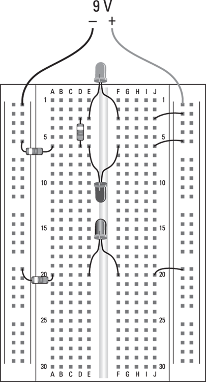
Project 27 shows how to build this circuit configured as an interrupter, and Figure 4-8 shows the finished project. When you connect this circuit to power, the red LED stays dark. But if you pass an object between the IR LED and the phototransistor, the red LED turns on.

FIGURE 4-8: This circuit lights a red LED when the path between an IR LED and a phototransistor is blocked (Project 27).
Project 27: A Common-Collector Proximity Detector
In this project, you can build a common-collector proximity detector that lights a red LED whenever something comes between an infrared LED and a phototransistor.


Parts
- One 9 V battery snap holder (RadioShack 2700325)
- One 9 V battery
- One IR phototransistor (RadioShack 2760145)
- One IR LED (RadioShack 2760143)
- One red LED (RadioShack 2760209)
- Two
 resistors (orange-orange-brown)
 - One
 resistor (orange-orange-orange)
 - Three short lengths of jumper wire
Steps
Throughout these steps, use the negative (–) bus strip on the left side of the board for ground and the positive (+) bus strip on the right side of the board as the positive voltage.
-
Insert the red LED.
Insert the LED as follows.
Cathode (Long)
Anode (Short)
E3
F3
-
Insert the photodiode.
Insert the photodiode as follows.
Collector (Short)
Emitter (Long)
F6
E6
-
Insert the IR LED.
Insert the IR LED as follows.
Cathode (Short)
Anode (Long)
E20
F20
- Insert the resistors.
Resistor
From
To

A20
Ground bus

A6
Ground bus

D3
D6
-
Insert the jumper wires.
Insert the jumper wires as follows:
From
To
J3
Positive bus
J6
Positive bus
J20
Positive bus
-
Connect the battery.
Attach the red lead to the positive bus and the black lead to the negative bus.
-
Use a piece of paper or other flat object to block the light path between the IR LED and the phototransistor.
The red LED will light up when you interrupt the light path between the IR LED and the phototransistor. When you remove the obstacle, the red LED will go dark.