
In Chapter 5, we looked at our very first circuit and how to draw it using a circuit diagram. In this chapter, we are going to look at different ways components can be hooked together and what they mean for your circuit.
7.1 Series Circuits
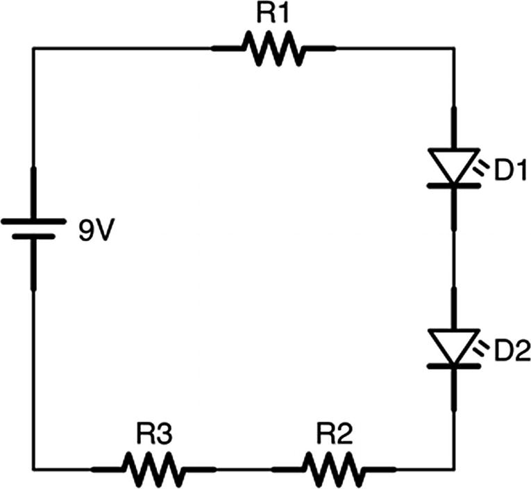
The circuit built in Chapter 5 is considered a series circuit because all of the components are connected end to end, one after another. In a series circuit, there is only one pathway for the current to flow, making analyzing the circuit fairly simple.
A Series Circuit with Several Components
If all of the components are in a series, then, even if there are multiple resistors scattered throughout the circuit, you can figure out the total resistance of the circuit just by adding together all of the resistances. This is known as the equivalent resistance of the series.
In this example (Figure 7-1), if R1 is 100 Ω, R2 is 350 Ω, and R3 is 225 Ω, then the total series resistance of the circuit will be 100 + 350 + 225 = 675 Ω.
That means that the current is easy to figure out as well. If we ignore the LEDs (since we have not yet learned to calculate using them), then we can use the total series resistance to calculate current the same way we did with the single resistor.


So our circuit will draw about 13 milliamps of current. This amount of current is the same amount running through all of the components in the series.
7.2 Parallel Circuits
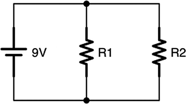
Circuits are wired into a parallel circuit if one or more of their components are arranged into multiple branches.
Two Resistors Wired in Parallel
In a parallel circuit, electricity will flow through both branches simultaneously. Some of the current will go through R1 and some of it will go through R2. This makes determining the total amount of current more difficult, as we have to take into account more than one branch.
However, there are two additional laws we can use to help us out, known as Kirchhoff’s circuit laws. The guy’s name is hard to spell, but his rules are actually fairly easy to understand.
7.2.1 Kirchhoff’s Current Law
The first law is known as Kirchhoff’s current law. Kirchhoff’s current law states that, at any junction, the total amount of current going into a junction is exactly the same as the total amount of current going out of a junction. This should make sense to us. Think about traffic at a four-way intersection. The same number of cars that enter that intersection must be the same number of cars that leave the intersection. We can’t create cars out of thin air; therefore, each car leaving must have come in. Cars don’t magically disappear; therefore, each car entering must leave at some point. Therefore, Kirchhoff’s circuit law says that if you add up all of the traffic going in, it will equal the amount going out.
Another way to say this is that the total amount of all of the currents at a junction is zero. That is, if we consider currents coming in to the junction to be positive and currents going out of the junction to be negative, then their total will be zero since the size of the currents coming in must equal the size of the currents going out.
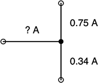
A Simple Junction
Since the total coming in must equal the total coming out, then that means the total coming in must be
0.75 A + 0.34 A = 1.09 A
Therefore, the total amount of current coming into the circuit is 1.09 A.
Now, let’s say we had a junction of four wires. On the first wire, we have 0.23 A of current coming in. On the second wire, we have 0.15 A of current going out. On the third wire, we have 0.20 A of current going out. What must be happening on the fourth wire? Is current coming in or going out on that wire?
To figure that out, we have to look at the totals so far. Coming in, we have the one wire at 0.23 A. Going out, we have the two wires for a total of 0.15 A + 0.20 A = 0.35 A. Since we only have 0.23 A coming in, but there is 0.35 A going out, that means that the fourth wire must be bringing current in. Therefore, the amount that this fourth wire must be bringing in is 0.35 A − 0.23 A = 0.12 A.
7.2.2 Kirchhoff’s Voltage Law
Kirchhoff’s current law makes a lot of sense, because the amount of “stuff” coming in is the same as the amount of “stuff” going out. This is similar to our everyday experience. Kirchhoff’s voltage law, however, is a bit more tricky. Kirchhoff’s voltage law states that, given any two specific points on a circuit at a particular time, the difference in voltage between the two points (known as the voltage drop) is the same no matter what pathway you take to get there.
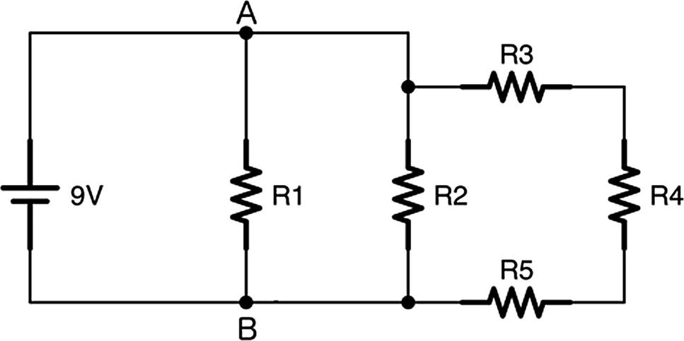
A Circuit with Many Parallel Paths
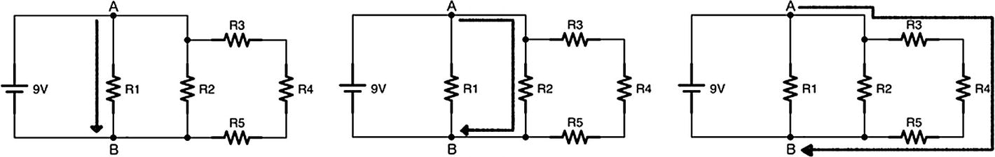
All Paths Between Two Points Have the Same Voltage Drop
So how does that square with Ohm’s law?
The way it works is that Ohm’s law will cause all of the currents through each part of the circuit to adjust in order to make sure that the voltage stays the same.
As you can see, the voltage drop between A and B must be 9 volts because the battery is a 9-volt battery, and there are no components (only wires) between the battery terminals and A and B. Since batteries always have a constant voltage between their terminals, that means that A and B will have the same voltage—9 volts.
Therefore, that means that the voltage drop across R1 is 9 volts, because it is one of the pathways between A and B, and all pathways get the same voltage. Let’s put in some real values for these resistors and see if we can figure out how much voltage and current is happening in each part of the circuit. Let’s set R1 = 1,000 Ω, R2 = 500 Ω, R3 = 300 Ω, R4 = 400 Ω, and R5 = 800 Ω. Now, let’s find out what our circuit looks like.

So we have 0.009 A running across R1.

So the current going across R2 is 0.018 A.
What about the current going across R3, R4, and R5? Well, if you notice, those resistors are all in series, so we can add them all up and just use the total resistance.


Now, remember that the total current flowing into any junction has to be equal to the current flowing out of it. So let’s look at the junction between R2 and R3. We calculated that the current flowing to R2 is 0.018 A and the current flowing to the series starting with R3 is 0.006 A. Therefore, there has to be 0.018 + 0.006 = 0.024 A flowing into that junction.
Now, how much current is flowing out of junction A? Well, earlier, we noted that the amount of current flowing across R1 was 0.009 A, and we just calculated that there is 0.024 A flowing out the junction between R2 and R3. That means that there must be 0.033 A total flowing into junction A.
While there were a lot of steps to determine this, each individual step was fairly straightforward. We simply combined Ohm’s law, Kirchhoff’s voltage law, and Kirchhoff’s current law to figure out each step.
Now, one important thing to notice is that there is less current running through the pieces of the circuit with more resistance than there is with the pieces of the circuit with less resistance. The electric current is more likely to go down the path of least resistance. This is a very important point and should not be overlooked, as it will come in handy in later chapters.
7.3 Equivalent Parallel Resistance
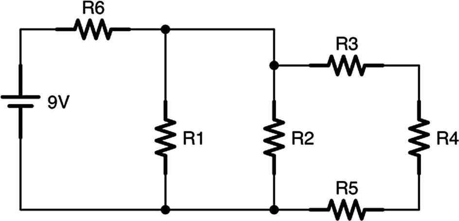
Kirchhoff’s Voltage Law with Series and Parallel Components
Thus, we have ourselves in a loop—in order to find out the current flowing through the parallel branches, we have to know their starting voltage. In order to find out their starting voltage, we have to know how much the voltage dropped across R6. In order to know how much the voltage dropped across R6, we have to know how much current was flowing through it!
This may seem like an impossible problem, but basic algebra allows us to work it out, though the details are kind of ugly. Instead, there is an equation that we can use for parallel resistors which will give us an equivalent resistance for a group of parallel resistors. That is, we can take a group of parallel resistors, and we can calculate the total resistance of those resistors, as if they were acting together as one resistor. In other words, we can find out what value we would need for a single resistor to replace all of the other resistances.

This equation works for any number of resistances that we have in parallel. We can just keep on adding them to the end of the list:

So let’s look at our circuit and see how we can find out the current flowing through each resistor. For this example, we will again say that R1 = 1,000 Ω, R2 = 500 Ω, R3 = 300 Ω, R4 = 400 Ω, and R5 = 800 Ω. Additionally, R6 = 250 Ω.
In order to compute this, we first have to figure out what is in series and what is in parallel. Notice the loop made by R3, R4, and R5. Those are all connected end to end, so they are in series. Because they are in series, we can get their equivalent resistance just by adding them together—300 + 400 + 800 = 1,500 Ω. Therefore, we can actually replace these resistors with a single, 1, 500 Ω resistor. We will call this “combined” resistor R7. Now, if you look at the new picture, with R7 standing in for the loop, you will see that R1, R2, and R7 are in parallel with each other.

Therefore, the equivalent resistance of all of the parallel resistances is about 272.5 Ω, which means that we could in theory replace all of these resistors (R1, R2, R3, R4, and R5) with a single resistor that is 272.5 Ω. Also notice that this resistance is actually less than each of the individual resistances.

Thus, the whole circuit has 0.0172 ampere of current running through it. Using this, we can now go back through and identify how much current and voltage is flowing through each individual piece.

That means that this resistor will chew up 4.3 V. This leaves us with 9 − 4.3 = 4.7 V after the series resistor.
We now know the starting and ending voltages of each branch of the parallel resistors—4.7 V at the beginning (what we just calculated the voltage to be after the series resistor) and 0 V at the end (because it connects to the negative terminal of the battery, which we have designated as the 0-volt reference).


Since the loop is all in series, that means all of the resistors in that series will have 0.0031 A going through them.
If we add all of these currents, we will see that 0.0031 + 0.0094 + 0.0047 = 0.0172 A, which is the amount of current we originally figured out.
What we have learned is that we can replace the entire circuit with a single value for its resistance to figure out how the circuit will behave as a whole. For a simple circuit like this, having all of these parallel branches doesn’t do much, so it may seem pointless. However, in a real circuit, each of these branches may be, instead of a resistor, a more complicated component that has some amount of resistance. If you know the resistance, you can calculate how much current is flowing through it the same way.
However, we start with only resistors in order to make the problems simpler.
7.4 Wires in a Circuit

Showin Joined Wires (Left) vs. Showing Unjoined Wires (Right)
Also, the lengths of wires that we draw are irrelevant. Usually, in simple circuits, we should consider that wires are all zero length. If, after a resistor, the voltage in the circuit has dropped to 5 V, then we can consider that the whole wire until the next circuit is at 5 V. If a wire branches into multiple branches, even though each branch will have a different amount of current running on it, each branch of the wire will all have the exact same voltage until they reach another component.
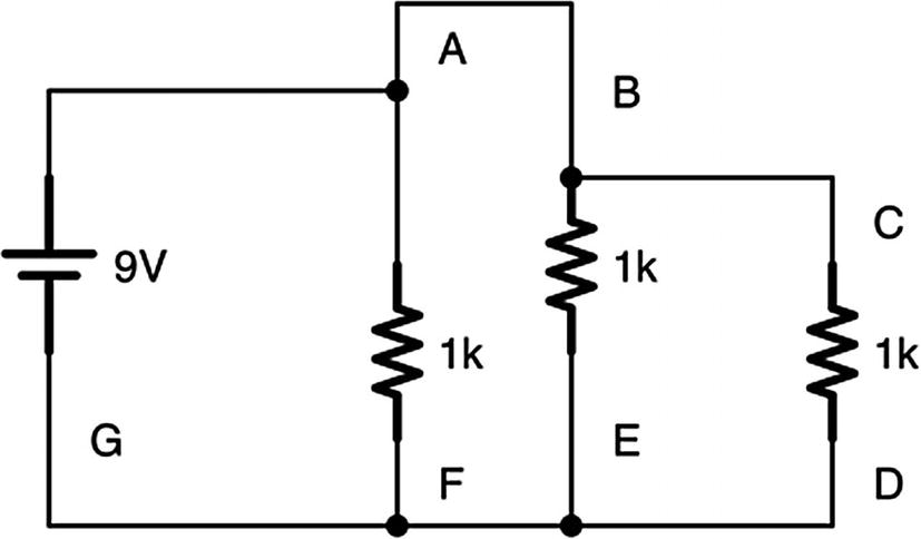
Several Points on a Circuit
7.5 Wiring Parallel Circuits onto a Breadboard
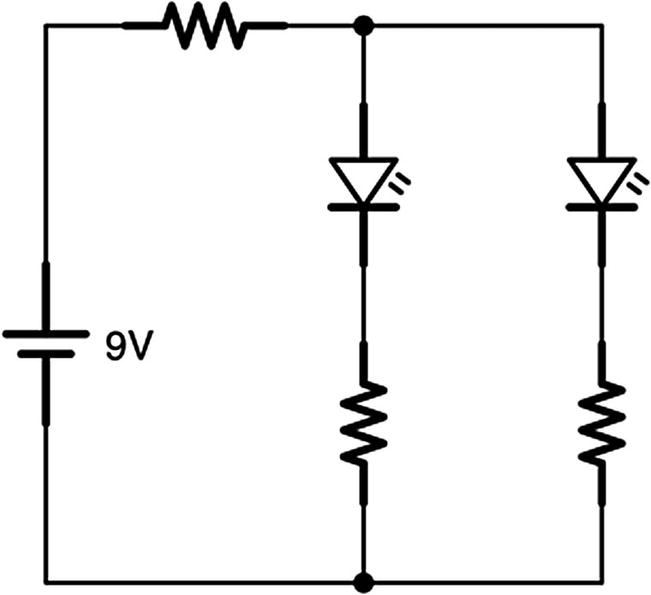
A Circuit with Series and Parallel Components
Notice that, in this circuit, there is a series resistor at the beginning and then two parallel circuits that branch off from it. It doesn’t matter much what the value of the resistors are, but we will put them at 1,000 Ω if you need a specific value (anything between 200 and 2,000 Ω should work fine).

A Circuit with Series and Parallel Components on the Breadboard
Let’s follow the path of electricity through the breadboard. First, the current flows from the positive terminal to the positive rail on the breadboard. A wire then pulls the positive +9 V power onto the board. This wire is connected to a resistor by putting one leg of the resistor in the same terminal strip as the wire. On the other leg of the resistor, there are two wires that are in the same terminal strip. Each of these goes to a different part of the circuit. We have one LED with a resistor on the top and one LED with a resistor on the bottom. These are just normally connected components.
However, after the resistor, the two subcircuits come back together to a terminal strip on the right. Then, a wire on the same terminal strip takes that back to the negative rail on the breadboard (which connects to the negative terminal on the battery).
Note that I could have used a lot fewer wires to accomplish the same circuit. However, I thought that using more wires would make it more clear what is happening at each junction, especially when the circuit gets divided into branches or comes back together.
Take a moment to look at both the schematic drawing and the breadboard picture, and be sure that you can trace the flow of the schematic on the actual breadboard.
7.6 Review
- 1.
In a series circuit, electricity flows in a single line through all of the components.
- 2.
In a parallel circuit, electricity branches and flows in multiple branches.
- 3.
Most real circuits are combinations of series and parallel circuits.
- 4.
When you have resistors together in series, the total resistance of all of the resistors combined is simply the sum of their individual resistances. RT = R1 + R2 + … + RN.
- 5.
In a parallel circuit, Kirchhoff’s current law says that the total amount of current entering a branch/junction is the same as the total amount of current leaving the branch.
- 6.
In a parallel circuit, Kirchhoff’s voltage law says that, between any two points on a circuit at a given point in time, the voltage difference between those two points will be identical no matter what pathway the electricity follows to get there.
- 7.
When resistances are in parallel, the total resistance for the parallel circuit is given by the equation

- 8.
By using these laws in combination, we can predict how current will flow in each part of our circuit.
- 9.
Series circuits are placed onto a breadboard by putting the connected legs of two connected components onto the same terminal strip.
- 10.
Parallel circuits are placed onto a breadboard by connecting each subcircuit branch to the same terminal strip.
7.7 Apply What You Have Learned
- 1.
There is a junction in a circuit that has one wire with current flowing in and two wires with current flowing out. There is 1.25 A of current coming in, and the first wire going out has 0.15 A of current. How much current is leaving through the second wire?
- 2.
There is a junction in a circuit that has two wires with current flowing in and two wires with current flowing out. The first wire with current flowing in has 0.35 A of current, the first wire with current flowing out has 0.25 A of current, and the second wire with current flowing out has 0.42 A of current. How much current is flowing in on the second incoming wire?
- 3.
At a junction of four wires, wire 1 has 0.1 A of current flowing in, wire 2 has 0.2 A of current flowing in, and wire 3 has 0.4 A of current flowing out. Is the current in wire 4 going in or out? How much current is flowing on it?
- 4.
If I have three 100 Ω resistors in series, what is the total resistance of the series?
- 5.
If I have a 10 Ω resistor, a 30 Ω resistor, and a 65 Ω resistor in series, what is the total resistance of the series?
- 6.
If I have a 5 Ω resistor and a 7 Ω resistor in series, what is the total resistance of the series?
- 7.
If I have two resistors in parallel, a 30 Ω resistor and a 40 Ω resistor, what is the total resistance of this circuit?
- 8.
If I have three resistors in parallel—25 Ω, 40 Ω, and 75 Ω—what is the total resistance of this circuit?
- 9.
If I have four resistors in parallel—1,000 Ω, 800 Ω, 2,000 Ω, and 5,000 Ω—what is the total resistance of this circuit?
- 10.
If I have three resistors in parallel—100 Ω, 5,000 Ω, and 10,000 Ω—what is the total resistance of this circuit? Which of the resistors is the total resistance most similar to?
- 11.
Take a look at the following circuit diagram. If the voltage drop between B and C is 2 volts and the voltage drop between C and D is 3 volts, what is the voltage drop between A and E? What is the voltage at E? What is the voltage at A?
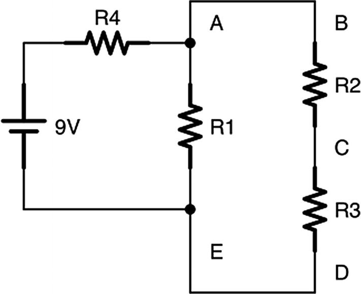
- 12.
If the preceding circuit runs with 2 A total current, what is the value of the resistor R4?
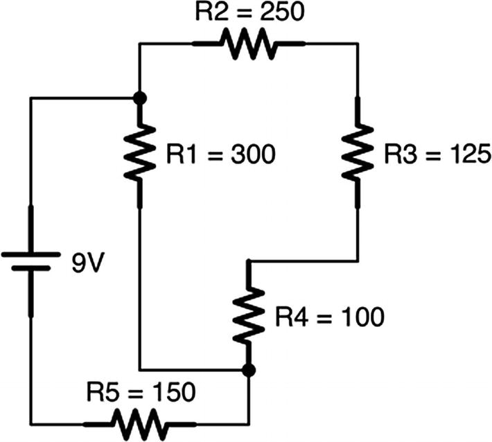
- 13.
The following circuit is a combination of series and parallel resistances. Each resistor is labeled with its resistance value, given in ohms. Find out how much current is flowing through each resistor and how much each resistor drops the voltage.
- 14.
Build the circuit in Figure 7-10 on your own breadboard. Measure the voltage drops across every component, and measure the amount of current flowing into the first series resistor.