
In this chapter, we will start looking at the capacitor.
16.1 What Is a Capacitor?
Before we begin discussing the capacitor, we need to quickly review the concepts from Chapter 3 on the relationship between charge, current, and voltage. In fact, it might be helpful to reread that chapter if you find that you have forgotten how those terms related to each other.
Charge is essentially the amount of electrical “stuff” (positive or negative) that something contains, measured in coulombs.
Current is the movement of charge, measured in coulombs per second, also known as amperes.
Voltage is the amount of force that each coulomb will produce. You can think of it as the amount of electric energy that each coulomb is capable of producing or the amount of power that each ampere of current yields.

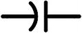
The Symbol for a Capacitor
The size of a capacitor is known as its capacitance, and it is measured in farads (abbreviated with the letter F), named after the influential scientist Michael Faraday. A capacitance of 1 farad means that if a capacitor stores 1 coulomb of charge, it will discharge with a force of 1 V. Most capacitors, however, have a capacitance much lower than a farad. Capacitors are usually measured in microfarads (1 millionth of a farad, abbreviated as μF or uF), nanofarads (1 billionth of a farad, abbreviated as nF), or picofarads (1 trillionth of a farad, abbreviated as pF). Capacitors are rarely rated in millifarads (1 thousandth of a farad).
So, to convert from microfarads to farads, multiply the capacitance by 0.000001. To go back from farads to microfarads, multiply the capacitance by 1000000. To convert from picofarads to farads, multiply the capacitance by 0.000000000001. To go back from farads to picofarads, multiply the capacitance by 1000000000000.
16.2 How Capacitors Work
The symbol for a capacitor in a circuit is shown in Figure 16-1. This symbol provides a visual reference for how a capacitor works. Capacitors usually work by having two conductive plates or surfaces that are separated by some sort of nonconductive material. Since the two plates are near each other, having a charge in one of the plates will pull charge into the other plate due to the electric field . An electric field is generated any time a charge accumulates. Essentially, an electric field pulls an opposing charge closer in.
Electric fields influence nearby charges even though they don’t directly touch. The field will pull opposite charges closer to itself. Therefore, having a charge in one plate will attract the opposite charge in the other plate. However, since the plates are not actually touching, the electrons cannot actually jump the gap. Therefore, the capacitor will accumulate a certain amount of charge and hold it in its plates.
To understand this better, imagine that you are a positive charge. You are moving through the circuit, but why? What are you moving toward? As a positive charge, you are trying to move to the negative charge. So then, moving along, you see this big swimming pool (i.e., a capacitor). At the bottom of the swimming pool, the barrier is so thin that you can see to the other side. And what do you see there? It’s the negative charges—right there at the bottom of the swimming pool! The negative charges have their own swimming pool the size of your own, separated by a barrier so thin that you can see each other.

A Simple Circuit to Charge a Capacitor
When the pressure (voltage) to push charge out of the swimming pool equals the pressure (voltage) of the pipe (wire) leading to the swimming pool (capacitor), then the capacitor is full. When the voltage on the wire goes down (i.e., the battery disconnects), then the pressure of the charges in the capacitor pushes them back out into the wire, discharging the capacitor.
So, if one terminal of the capacitor is connected to the positive side of a battery and the other terminal is connected to the negative side of a battery, charge will quickly flow into the capacitor, as happened in our example with the swimming pool. Figure 16-2 shows this circuit setup. The exact amount of charge that flows in depends on the voltage of the battery and the capacitance of the capacitor (i.e., the size of the swimming pool). Note that this is not a short circuit, because the two plates of the capacitor are not actually connected. They are just close enough to attract the opposite charge onto the opposite plate.

Example 16.7 If I attached a 66 μF capacitor to a 9 V source, how much charge gets stored on the capacitor?
Well, first, we need to convert the capacitance from microfarads to farads. 66 μF is 66 millionths of a farad, so it would be 0.000066 F. Now, we just need to plug the numbers into the equation:

Therefore, if I attached a 66 μF capacitor to a 9 V source, the capacitor would store 0.000594 coulomb of charge.
After my capacitor is charged up, I can use it as a very tiny battery. That is, I could disconnect it from the circuit in Figure 16-2 and reconnect it as the battery for another circuit. However, as I mentioned, this will be a very, very tiny battery. Additionally, as the charge leaves the capacitor, the voltage of the battery will decrease as well.

Example 16.8 If I have a charge of 0.0023 coulomb stored in a 33 μF capacitor, if I discharge the capacitor, what voltage will it begin to discharge at?
The first thing to do here is to convert the capacitance to farads. A microfarad is 1 millionth of a farad, so 33 μF = 0.000033 F. Now we can just plug numbers into the equation:

Therefore, when the capacitor discharges, it will discharge at 69.7 V.
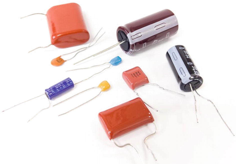
Several Different Types of Capacitors (Shutterstock/Muhammad Anuar bin Jamal)
16.3 Types of Capacitors
There are numerous types of capacitors available, each varying in the types of materials they are made of, the internal geometry of the capacitor, and the packaging. Figure 16-3 shows many different types of capacitors that are available.
However, the most important feature of capacitors besides their capacitance is whether they are polarized or non-polarized. In a non-polarized capacitor, it doesn’t matter which way you attach the leads. Either side can be the more positive or more negative side. The most common type of non-polarized capacitor is the circle-shaped ceramic disk capacitor. While ceramic disk capacitors are easy to use, they suffer from having limited capacitance.
In a polarized capacitor , however, one lead must stay more positive than the other lead, or you risk damaging the capacitor. The most common type of polarized capacitor is the electrolytic capacitor. Electrolytic capacitors look like little barrels with leads coming out of them. They usually have much higher capacitances than ceramic disk capacitors, but you have to be sure that the polarity is correct and never switches direction.
A Polarized Capacitor Symbol
- 1.
One or both of the leads can be marked with their respective polarities (+ or -).
- 2.
The negative lead can be marked with a large stripe.
- 3.
The positive lead can be longer than the negative.
Many manufacturers do all three.
In a circuit schematic, if a polarized capacitor is called for, it will use a special capacitor symbol as shown in Figure 16-4. The only difference is that one side is curved. In a polarized capacitor, the straight side is the positive side, and the curved side is the negative side. Sometimes polarized capacitors are marked with plus (+) and minus symbols (-) instead of (or in addition to) having a straight side and a curved side.
On any capacitor, it is important to know the capacitance of the capacitor you are looking at. On larger capacitors (especially on electrolytics), manufacturers can print the full capacitance including the units directly on the capacitors. However, many capacitors are extremely small and can’t fit that much information on them.
For smaller-sized capacitors, the capacitance is described by three digits and an optional letter. The third digit is how many zeros to add to the end of the other two digits, and then the whole number is the capacitance in picofarads. So, if the number is 234, then the capacitance is 230,000 pF (23 followed by four zeros). If the number is 230, then the capacitance is 23 pF.
The letter at the end tells the tolerance of the capacitor—how much the capacitance is likely to vary from its markings. Common letters are J (±5%), K (±10%), and M (±20%).
16.4 Charging and Discharging a Capacitor
To charge up a capacitor almost instantly to a specific voltage, you can (as we also did earlier in the chapter) directly connect the positive and negative leads of the battery to the leads of the capacitor. Once it it charged, you can use the capacitor as a very tiny battery for a project.

Using a Capacitor as a Battery
Now, you will notice that the LED gets dimmer before it goes out. Why does this happen?
Example 16.9 If we use the components listed in Figure 16-5, how much charge does the battery initially store in the capacitor?
We can use Equation 16.1 to determine this:

Example 16.10 After 0.0003 coulomb of charge has been discharged, what voltage is the capacitor discharging at?
To find this out, we first have to find out how much charge is remaining in the capacitor. So, to find this out, we just subtract the amount of charge that has been discharged from our starting charge. This gives 0.0009 − 0.0003 = 0.0006 coulomb.
Now, we can use Equation 16.2 to find out what voltage the capacitor is discharging at:

Therefore, the capacitor is discharging at 6 V.
16.5 Series and Parallel Capacitances
Just like resistors, capacitors can be used either in series or in parallel. In fact, they use the same equations for series and parallel capacitance as do resistors. However, there is one big difference. The parallel and series versions of the equations are reversed for capacitors.


Example 16.11 If I have a 100 μF capacitor in series with a 200 μF capacitor, how much total capacitance do I have?
To do this, we use Equation 16.4. It is best to convert our capacitances to farads first. It does not matter as long as the units are the same, but it is good practice to convert to farads so you don’t forget when you start doing capacitances in different units. 100 μF is the same as 0.0001 F, and 200 μF is the same as 0.0002 μF.

Capacitors in Series and Parallel

Example 16.12 Just as we did for resistors, we can combine a variety of parallel and series capacitances for a single capacitance value. For instance, take the circuit in Figure 16-6. What is the total capacitance of this circuit?
First, we can start by converting all of the capacitances to farads. This will make combining everything easier down the road. In that case, C1 = 0.00001 F, C2 = 0.00003 F, C3 = 0.0000000008 F, and C4 = 0.0000000005 F. C3 and C4 are in parallel, so we can combine them using the parallel formula (Equation 16.3):


So the total capacitance of the circuit is 1.3 nF.
16.6 Capacitors and AC and DC
One important characteristic of a capacitor is that it allows the flow of AC (alternating current) but it blocks the flow of DC (direct current). To understand why this is, let’s think about how capacitors operate.
Capacitors, when they are charging, essentially act as short circuits. As positive charge flows into the capacitor at one terminal, negative charge flows into the other side. An inflow of negative charge to that side means that there is a net outflow of positive charge on that side. So, even though the physical electrons never cross the boundary between the plates, the total charge actually moves from one side to the other.
However, this situation is temporary because, as the capacitor gets more full of charge, new charge is less likely to enter. Once the capacitor is fully charged (based on the voltage), no new charge can flow into one side to cause the charge to go out to the other.
Once the capacitor is charged, current stops flowing through it. If the voltage level on one of the leads changes, then charge will flow until the change is compensated for by the capacitor charging or discharging.
Thus, because there is a barrier between the two sides of a capacitor, it is only when the voltage changes that the current flows through a capacitor. If the voltage stays the same, then charge will stop flowing through the capacitor as soon as it reaches capacity for that voltage.
Because of this, we say that capacitors allow AC but block DC . This rule of thumb will help us use capacitors in a variety of circuits later on.
16.7 Using Capacitors in a Circuit
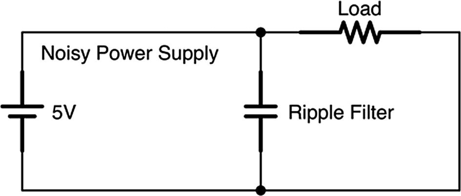
A Capacitor Filtering a Noisy Power Supply
The first thing that capacitors are used for is for filtering noisy signals, especially in power sources. Imagine that you had a power source which, instead of delivering a constant voltage, the voltage would wobble a bit. If you placed a capacitor in parallel with this circuit, the power source would charge the capacitor up. Then, if the power source dropped a bit, the capacitor would start discharging to compensate. Likewise, if the power source increased, the capacitor would absorb some of that increase by storing the charge.
Thus, by acting as a temporary location to store extra charge, the capacitor can smooth out ripples in a signal, as seen in Figure 16-7. This sort of usage is known as a filtering capacitor because it filters out noise.
This can be seen as another implementation of our rule that capacitors allow AC to flow but block DC. When the source voltage has a ripple, the ripple itself gets shunted to ground by the capacitor. However, under normal operation, the DC part of the current can’t flow through the capacitor and just continues on to the load.
On many ICs that have fluctuating power requirements, you will find many of their spec sheets recommending one or more capacitors on their power supply or other pins in order to filter out the noise.
Another way of using capacitors is as a coupling capacitor. A coupling capacitor is used when you have both an AC signal and a DC signal combined. This will happen a lot when we talk about amplification. What happens is that we will have an amplified signal, but we only want the AC portion of the signal. We can do that by adding in a capacitor to join the segment of the circuit that has both AC and DC components to the segment of the circuit that only wants the AC component. Only the variations in the voltage, not the base voltage, will be transmitted through the capacitor.
Another way that capacitors are used is for filtering specific frequencies. Higher-frequency signals are easily transmitted through a capacitor, but low-frequency signals are essentially blocked as if they were DC. The frequencies that are allowed are based on the capacitance. If you put a capacitor in series with the signal path, then it will only allow higher frequencies. If you put a capacitor in parallel with the signal path, then it will ony allow lower frequencies (the higher frequencies will be shunted to ground).
If you see a capacitor in any sort of equipment, do not touch it, even with the power off. Because capacitors store charge, they can still hold onto the charge even after the power is off. If you need to touch a capacitor for some reason, use a resistor to discharge it. Placing a large (megaohm) resistor between the leads of a capacitor (without touching the leads yourself!) for a few seconds should drain most capacitors. You can also use a multimeter to determine that the capacitor is drained (0 volt).
16.8 Review
- 1.
An electric field is generated wherever there is an accumulated charge.
- 2.
A capacitor is a device that stores electric energy by holding two opposing charges.
- 3.
Capacitors are sized by their capacitance which is measured in farads.
- 4.
Because a farad is so large, capacitors are usually measured in microfarads, nanofarads, or picofarads.
- 5.
Polarized capacitors (usually electrolytic capacitors) have distinct positive and negative terminals, while non-polarized capacitors (usually ceramic disk capacitors) can go either way.
- 6.
When a battery is connected to a capacitor, it will store a charge on the capacitor.
- 7.
The equation for the charge (Q) stored on the capacitor when a battery is connected is Q = C ⋅ V where C is the capacitance in farads, V is the voltage, and Q is the charge in coulombs.
- 8.
By rearranging the equation, we can determine, for a given amount of charge, how much voltage a capacitor will discharge when it is allowed to:
 .
. - 9.
As the capacitor discharges its charge through the wire to create current, the amount of charge remaining will decrease, which will also lower the voltage it is putting out.
- 10.
Capacitors with small packages are often marked with a three-digit code, where the third digit is the number of zeros to add to the other two digits and the final number is in picofarads.
- 11.
When multiple capacitors are used together, their capacitances can be combined similar to resistors, but with the series and parallel equations switched.
- 12.
The series capacitance equation is as follows:

- 13.
The parallel capacitance equation is as follows: CT = C1 + C2 + …
- 14.
Capacitors allow the flow of AC through them but block the flow of DC.
- 15.
Capacitors can be used to split AC (high-frequency) and DC (low-frequency) portions of a signal. The AC portion will travel through the capacitor, while the DC portion will remain on one terminal side.
- 16.
Capacitors can be used to filter audio frequencies, filter power supply ripples, operate as voltage boosters, and couple together a combined AC/DC circuit with an AC-only circuit.
16.9 Exercises
- 1.
Convert 23 F to microfarads.
- 2.
Convert 15 μF to farads.
- 3.
Convert 35 pF to farads.
- 4.
Convert 0.0002 F to microfarads.
- 5.
Convert 0.0030 μF to farads.
- 6.
If a voltage of 6 V is applied to a 55 μF capacitor, how much charge would it store?
- 7.
If a voltage of 2 V is applied to a 13 pF capacitor, how much charge would it store?
- 8.
If a 132 μF capacitor is holding 0.02 coulomb of charge, how many volts will it produce when it begins to discharge?
- 9.
If a 600 pF capacitor is holding 0.03 coulomb of charge, how many volts will it produce when it begins to discharge?
- 10.
A 121 μF capacitor is connected to a battery. After some fluctuation, the capacitor has 0.00089 coulomb of charge stored in it, and the battery is reading 8.9 V. Is the capacitor going to be charging or discharging at this point?