
In Chapter 17, we learned how to use RC (resistor-capacitor) circuits to create timers. In this chapter, we are going to use our concept of timing circuits to move from one-time timer circuits to oscillating circuits.
18.1 Oscillation Basics
So far, most of the circuits we have made have been fairly directional. You do an action (i.e., press a button) and then something happens, but then the circuit just maintains a steady state after that. In Chapter 17, we at least added a delay—allowing the circuit to do something later.
However, if you want actions to continue on into the future, you need to not only have delays, you need to have oscillations. Oscillation means to go back and forth. An oscillating circuit is one that goes back and forth continually between two states—usually zero voltage and some positive voltage. Imagine blinking lights at Christmas. These lights go from a state of zero voltage (off) to a state of positive voltage (on). And they go back and forth between these states over and over again as long as there is power in the circuit. These are oscillating circuits.
An oscillator is usually described by either its period or its frequency. The period of an oscillator is how many seconds it takes to go through one complete cycle. So, if I had lights that blinked on for 1 second and then off for 2 seconds (and continued repeating in that fashion), the period would be 3 seconds.
 cycle per second. The “cycles per second” unit of frequency also has a special name—hertz (often abbreviated as Hz). Therefore, we would say that our blinking lights blinked at a frequency of
  Hz.
Hz.Example 18.15 Let’s say that we have an oscillator that turns a light on for 4 seconds and then turns off for 4 seconds and repeats this continually. What is the period and frequency of this oscillator?
The period is merely the total time it takes to go through one complete cycle. Therefore

So what is the frequency of this oscillator? Simple—just take the reciprocal of the period. That makes the frequency
 Hz.
Hz.Example 18.16 On a piano, the middle-C key plays a sound with a frequency of 261.6 Hz. What is the period of this sound?
Since the frequency is the reciprocal of the period, it works the other way around as well—the period is the reciprocal of the frequency. Therefore, the period is simply
 second. Or, as a decimal, this is 0.00382 second.
There are many other factors that are important to various kinds of oscillations, such as the speed of transition between states, what percentage of time each state is achieved, and so on. However, the period/frequency is a good way to summarize the behavior of an oscillator into a single number.
18.2 The Importance of Oscillating Circuits
Sound Production: Sounds and tones are made by moving a speaker back and forth, which is moved back and forth by electricity oscillating between different voltages.
Time Clocks: Every clock on earth operates by an oscillator. The clock simply counts the number of oscillations that have occurred to know whether or not to advance another time step (second, minute, etc.).
Hardware Coordination Clocks: In computers and other advanced hardware, system events are coordinated based on signals from an oscillating circuit. When the clock changes state from off to on (or the reverse), then the circuit does the next step in the process. The clock keeps the various circuits synchronized and keeps them from stepping on each other.
Radio Transmissions : Oscillators are used in radios in order to encode signals onto “carrier waves,” which are just oscillating signals run at a specific frequency.
Servo Motors : A servo is a motor which moves an arm to a specific angle (i.e., think of a car’s steering wheel). Servos are usually operated by frequencies, where each frequency specifies a different angle to move.
Let’s look in more depth about how sound is produced by oscillation. You hear sound through your eardrum, which communicates vibrations it detects to your brain which you interpret as sound. Therefore, any sound that you hear is merely the vibrations of your eardrum. In other words, your eardrum oscillates back and forth, which you interpret as sound.
What makes your eardrum move back and forth? The answer is oscillations in the air. What makes those oscillations happen? Oscillations in the sound speaker. When the speaker moves back and forth, it moves the air which produces sound that you hear.
But what moves the speaker back and forth? Oscillations in the voltage and current supplied to the speaker. The speaker has a magnet attached to it which responds to changes in voltage in the wire. As the voltage in the wire increases, it moves the speaker in one direction. As the voltage decreases, the speaker moves in the other direction. Thus, the oscillations in voltage eventually wind up as sound for your ears.
18.3 Building an Oscillator
Let’s think for a moment of what it would take to build an oscillator. An oscillator has (at least) two different states—on and off.1 Then, you have a time period of changing from one state to the other.
What sort of circuit have we looked at that provides a time period?
As we saw in Chapter 17, RC (resistor-capacitor) circuits can provide us with time delays. We can then use these time delays as the time periods between the states of the oscillation. What we need is a circuit that will give out a state (we’ll called it S1) for a time period (we’ll call it T1) and then move to another state (we’ll call it S2) and stay there for another time period (we’ll call it T2). After T2 is finished, the circuit moves back to state S1 and begins again.
Now, it is possible that we might be able to build such a circuit using multiple RC timers with multiple comparators. It is doable, but it is harder than it sounds. Thankfully, there is an integrated circuit that is built for making such timers—the NE555, often referred to as just a “555 timer” or just a “555.” The NE555 is a very flexible component, and engineers are constantly finding new ways to make use of it. However, we will just focus on using it as a basic oscillator.
It is easiest to describe how a 555 works if we start out by showing a simple circuit with it. The circuit in Figure 18-2 blinks an LED on and off.
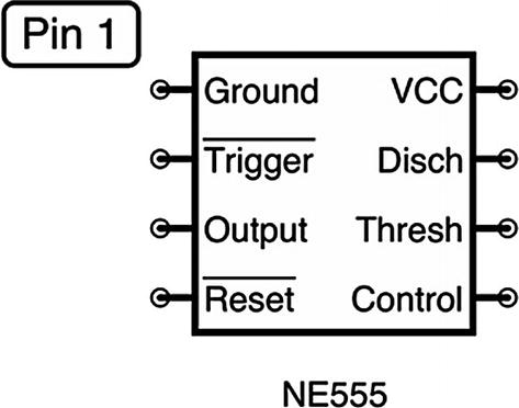
The 555 Pinout Diagram

A Schematic of a Simple 555 Oscillation Circuit
First, let’s look at the pins on the left-hand side of Figure 18-1 that are directly connected to the power rails. Pin 1 (Ground) and pin 8 (VCC) are easy enough—they are connected to ground and positive voltage, respectively. Pin 4 ( ) gets connected to the voltage source too. That is a reset pin which is activated if the pin receives a low voltage signal. Pins that are activated by low-voltage signals are often shown with a line over them.2 In our case, we never want to reset the chip, so we will just tie the reset pin to positive voltage which will prevent any accidental resets from changes in voltages in the environment.
Now, on the right-hand side at the top, you can see the LED connected to pin 3 (Output). Pin 3 is simply the output pin. It is an active output, meaning that it will supply current to the output on its own. We don’t need a pull-up resistor as we did for the LM393. Instead, we just need a current-limiting resistor for the LED. The regular NE555 output yields a voltage that is about 1.7 V less than the supply voltage and sources up to 200 mA before it breaks.
Note that there are other, low-power versions of the 555 timer that have other output characteristics. For instance, the LMC555 has an output voltage that is equal to the input voltage, but can only source about 100 mA. For our purposes, either one would work, as we are not doing anything precise with our output, nor are we sourcing very much current. However, any calculations we do will assume a typical NE555 component.
On the bottom right, pin 5 (Control) is connected through a 10 μF capacitor to ground. This is just a standard part of using the chip. You can’t effectively include capacitors in integrated circuits larger than a few picofarads, so many chips specify certain capacitors be attached to certain pins. The NE555 uses a 10 μF capacitor on pin 5 to provide voltage stability. In Chapter 16, we learned that capacitors act essentially like little batteries. This capacitor is doing just that. It is providing a short-term supply of charge in case there is a sudden change in current needs within the chip. For instance, when the output goes active, there may be a sudden need for charge. This capacitor supplies a quickly available reservoir of charge to the chip so that sudden changes in current needs will not affect other chip properties.3
Down the middle of the schematic is where all of the action happens. This is what controls the oscillation. It is essentially an RC circuit with (a) an extra resistor and (b) a few tie-ins to the chip. As we will see shortly, the capacitor will alternately charge and discharge. The capacitor itself is attached to two voltage sensors on the chip. The first sensor,  , watches the voltage on the capacitor and activates if the voltage falls below
  of the supply voltage (the line over the name of the pin indicates that it activates on a low value). The second sensor, Threshold, watches the voltage and will activate if the voltage goes above
  of the supply voltage.
The oscillator works by moving the capacitor voltage back and forth between  and
and  of the supply voltage. It is fairly obvious to see how the capacitor charges—it is a basic RC circuit using both of the resistors R1 and R2. So how does the capacitor discharge? The capacitor discharges through the action of the Discharge pin, pin 7. When the 555 starts up, pin 7 essentially acts as if it were not connected to anything, so you can basically ignore it. When the capacitor goes over the
  supply voltage and triggers the Threshold pin, the 555 will then connect pin 7 to ground.
 voltage down to
  voltage will be faster than the charge up.
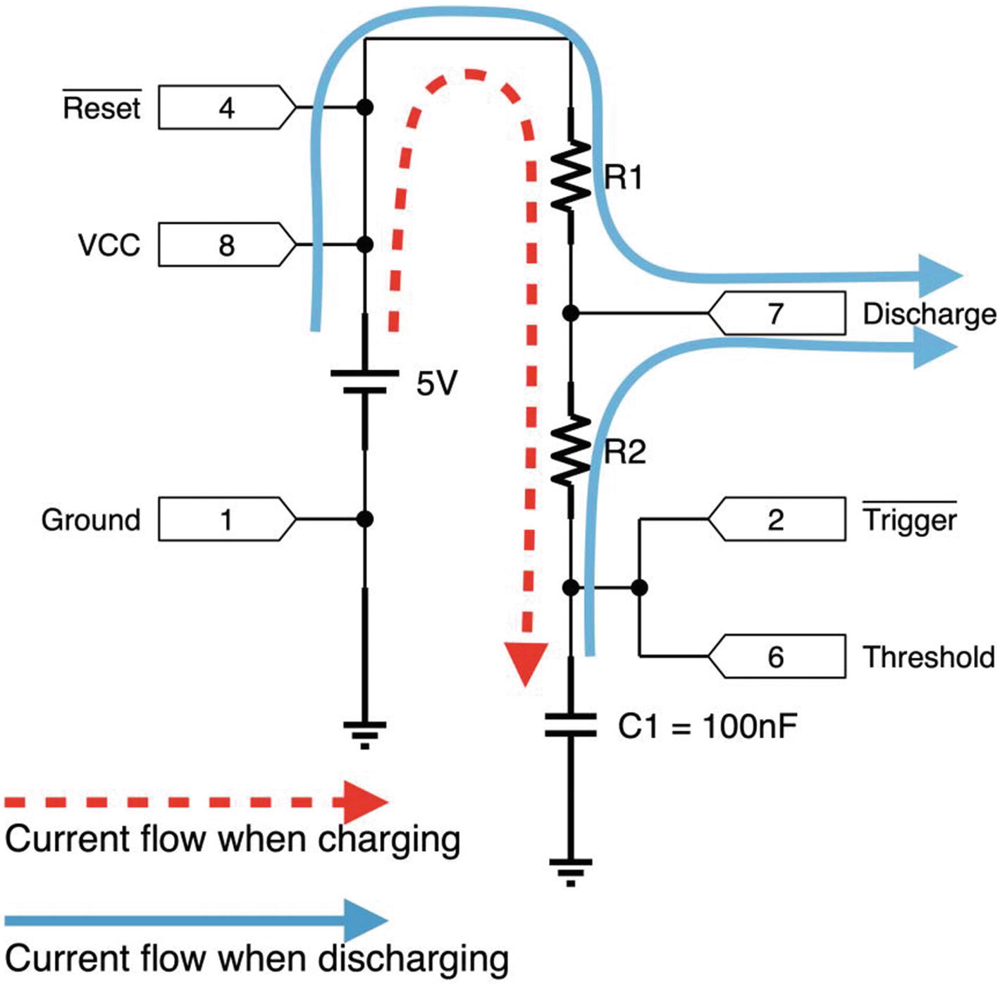
Current Flow During the Charge and Discharge Phases
Once the capacitor discharges down to  of supply voltage, pin 2 (
 ) will detect this event and turn pin 7 off so that the capacitor can recharge again. Therefore, the capacitor will be continually charging and discharging from
  to
to  of supply voltage, as the 555 turns pin 7 (connected to ground) on and off. This is also why having two resistors is so important. If we didn’t have R1, when pin 7 connected to ground, it would make a short circuit between the supply voltage and ground.
Figure 18-3 shows the different current flows of this part of the circuit during the charging and discharging phases.
 and Threshold to different parts of the circuit. For our purposes, both of these will always be used together.
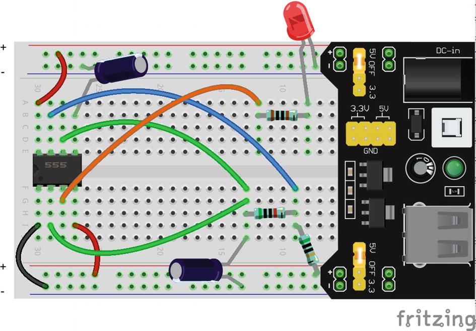
The 555 Oscillator Circuit on a Breadboard
So how does this charging and discharging of the capacitor affect the output? Quite simply, when the capacitor is charging, the output is on. When the capacitor is discharging, the output is off. Note that when we first turn on the 555, the output will be on for a little bit longer than for the rest of the time. This is simply because when the circuit first starts up, it is charging all the way from 0 V instead of from  of supply voltage.
You can see the completed 555 circuit on a breadboard in Figure 18-4. This should blink the light on for about two-thirds of a second and off for about a third of a second. This gives the total period of about 1 second and a frequency of about 1 Hz. In the next section, we’ll see how to use RC time constants to calculate our own on and off times.
18.4 Calculating On and Off Times with the 555
Remember that the capacitor is charging and discharging through an RC circuit. Therefore, we can use what we know about RC circuits to determine how long the output circuit will be high and low.
When the capacitor is charging, the capacitor is charging through both R1 and R2. In this situation, what is the RC time constant? First, we need to know the resistance. Since the resistance here is a series resistance, we can simply add them together:

So the resistance is 100,000 Ω, and we are using a 10 μF capacitor (which is 0.00001 F). Therefore (based on Chapter 17), the RC time constant is 100,000 ∗ 0.00001 = 1. So our RC time constant is 1 second. However, we are charging/discharging the capacitor in a strange way. We are not starting from zero (except for the first time)—instead we are usuallystarting from  of supply voltage.
Go
back to Chapter 17 and look at Figure 17-1. While we don’t have a time constant for exactly  of supply voltage, we do have one for 39.3%, which is pretty close. So, in the table, that occurs as 0.5 time constants. In this case, that is our starting value. Our ending value is when the capacitor is
  charged. That is very close to 63.2%, which is at 1 time constant. Therefore, the difference between the points where we are
  charged and
  charged is 1 − 0.5 = 0.5 time constants.
Since we were using approximate values from the table, this is only an approximation to see how this idea works. The distance from  to
to  of supply voltage actually takes 0.693 time constant. This is an important number to remember when using the NE555, as it will be used in all of your time calculations. Since our time constant is 1 second, that makes the calculation really easy: 1 ∗ 0.693 = 0.693 seconds.
Now, for discharge, remember that the point that the capacitor is discharging to is pin 7. This is between R1 and R2. That means that it is only using R2 to discharge, so the RC time constant will be based only on R2 and the capacitor. So the RC time constant is 50,000 ∗ 0.00001 = 0.5 seconds.Since the charge/discharge time between  and
and  is 0.693 time constants, the resulting time to discharge from
  down to
  is 0.693 ∗ 0.5 = 0.347 seconds.
The total period will be the total time for one cycle. This will be our charge time (0.693 second) plus the discharge time (0.347 second) which will give us a total of 1.04 seconds.
The value 0.693 looks like a strange number, but that will always be the value used for the number of time constants for charging/discharging between  and
and  of supply voltage. If you are going to use the 555 timer, it is best to just memorize it.
Example 18.17 Let’s say we have the basic oscillator circuit shown in Figure 18-2, but with a 2,000 Ω resistor for R1, a 6,000 Ω resistor for R2, and a 10 μF capacitor for C1. What will be the charge time, the discharge time, the period, and the frequency for our oscillator?
To find this out, it is easiest to first calculate the charge and discharge times separately and then use those to find period and frequency. The charge time will be calculated based on both resistors in our RC circuit. So the resistance will be 2,000 Ω+6,000 Ω = 8,000 Ω. The capacitance is 10 μF = 0.00001 F. This means that the RC time constant will be 8,000 Ω ∗ 0.00001 F = 0.08 seconds.
The number of time constants it takes to charge from
 to
to  is 0.693. This means that the charge time will be 0.08 ∗ 0.693 = 0.0554 seconds.
The discharge happens only through R2. This means that the RC time constant will be 6,000 Ω ∗ 0.00001 F = 0.06 seconds. Since we will use 0.693 time constants, the total time it takes to discharge from
 down to
  is 0.693 ∗ 0.06 = 0.0416 seconds.
Now that we have the charging and discharging times, we find the period by merely adding them together. This means the period is 0.0554 + 0.0416 = 0.097 seconds.
The frequency is merely the reciprocal of this number, or
 , which gives us 10.3 Hz.
Example 18.18 Now let’s say that we want to build an oscillator for which the LED stays on for 3 seconds and then goes off for 2 seconds. Assuming we keep our 10 μF capacitor, what values should we use for each resistor?
To do this, we need to solve for R2 first, since it is much easier. The discharge will be 2 seconds, which will be the same as 0.693 time constants. Therefore, we can write this as an equation:

So the resistor, R2, needs to be 289,555 Ω.


So now we know our values for R1 and R2—144,928 Ω and 289,855 Ω. Depending on our application, we would probably simply choose resistors that were close to that amount (like 150 kΩ and 300 kΩ) rather than trying to find a combination of resistors that hit that precise resistance. But, for solving equations, it is best to use exact values.
18.5 Choosing the Capacitor
Ultimately, there are no hard-and-fast rules for choosing capacitors. As long as the RC time constant yields the right value, then you can compensate for pretty much any size capacitor with the right size of resistor. However, sometimes just having a little guidance helps people get started, and there are a few situations that you need to watch out for.
First of all, the size of the capacitor will affect the size of the resistor you need for a given time constant. If all you have are smaller-sized resistors, then you should probably use a larger capacitor to compensate.
However, using a smaller capacitor with larger resistors gives a very large advantage in the amount of wasted current. If you are using smaller resistors, then Ohm’s law indicates that we will have larger currents for a given voltage. Since V = I ⋅ R, if you lower the R, you will increase the I. So having a higher resistance means that your RC circuit will use much less current.
Remember that we aren’t actually using the current to do anything except keep time. The current in our RC circuit is not used to power the LED (the 555 does that through the power source), and it isn’t used for anything else; it is just used to keep time. Therefore, pretty much all current used by the RC circuits is wasted. We have to use it, but any smaller currents we can get away with, we should!
This gets even more pronounced when the capacitor is discharging. When pin 7 (Discharge) switches to ground, not only does it discharge the capacitor but it also creates a useless waste of current going from the voltage source through R1. In our oscillator configuration, you can’t get rid of this, but having larger resistors will reduce the amount of waste.
So, in short, if you have higher-valued resistors to compensate, your circuit will waste much less current by using smaller capacitors.
18.6 Review
- 1.
Because this material is based so heavily on RC circuits, you may want to review the material in Chapter 17.
- 2.
When something oscillates, it moves back and forth between a set of values.
- 3.
In electronics, oscillators usually refer to circuits whose output voltages go back and forth between two different values.
- 4.
Oscillations are usually described by their period or frequency.
- 5.
The period of an oscillation is the time that it takes to go through one entire cycle (usually in seconds).
- 6.
The frequency of an oscillation is the number of times that an oscillation occurs per second, which is simply the reciprocal of the period (i.e.,
 ), with a unit of hertz (cycles per second).
 - 7.
Oscillating circuits are used in a number of circuit applications, including sound production, time keeping, coordinating activities, radio transmissions, and motor control.
- 8.
Oscillating circuits are often built with RC time circuits which control the time periods of the oscillations.
- 9.
The NE555 (often referred to as a 555 timer or just the 555) is an integrated circuit which allows for several timing applications including making oscillating circuits.
- 10.
The NE555, when set up as an oscillator, is controlled by two resistors and a capacitor.
- 11.
The NE555 can be set up to monitor the charge of the capacitor. It has two pins for monitoring the voltage,
 (which checks for the capacitor to drop below
  of supply voltage) and Threshold (which checks to see when the capacitor is charged above
  of supply voltage).
 - 12.
The NE555 cycles between charging and discharging the capacitor from
 of supply voltage to
  of supply voltage and back (using
  and Threshold to check the voltage level).
 - 13.
The Discharge pin of the NE555 acts like it is disconnected when the capacitor is charging and is connected to ground to allow for a path for the capacitor to discharge when in the discharge part of the cycle.
- 14.
The Output pin of the NE555 is turned on (higher voltage level) while the capacitor is charging and off (low voltage level) when the capacitor is discharging.
- 15.
The NE555 output operates at about 1.7 V less than the source voltage when on and can source a maximum of 200 mA to the output circuit.
- 16.
The
 pin can be given a low voltage to reset the whole device. If it is unused, it should just be tied to a positive voltage line.
 - 17.
The Control pin is attached to a capacitor in order to regulate and stabilize the circuit operation.
- 18.
The RC circuit takes 0.693 time constants to charge from
 voltage to
  voltage or to discharge the other way. Therefore, once you have the RC time constant, multiply by 0.693 to find the actual time it will take.
 - 19.
The RC circuit utilizes both resistors when charging, but only one resistor when discharging. This means that charging and discharging each have their own RC time constants.
- 20.
Because the charge circuit uses two resistors while the discharge circuit only uses one, the charging portion of the oscillation period will always be at least a little longer than the discharging portion.
- 21.
The period of the oscillation is the combination of both the charge time and the discharge time.
- 22.
When calculating for resistors for an RC time circuit, it is best to calculate the discharge resistance first, since it only uses one resistor (R2). Then you can calculate the combined resistance for the charge circuit, which allows you to deduce what the R1 resistor should be.
- 23.
When choosing components for a given RC time constant, you can choose a variety of combinations of capacitor/resistor values for the same result. Choosing a smaller capacitor and a larger resistor will save power in the circuit.
- 24.
An equation for determining the frequency of a 555 oscillator circuit can be found in Appendix D, Section D.4, “555 Timer Oscillator Frequency Equation.”
18.7 Apply What You Have Learned
- 1.
Copy Figure 18-2 to a piece of paper including the current flows on charge and discharge.
- 2.
Why is R1 important? What would happen if we just replaced it with a wire?
- 3.
Why are there two different pins on the NE555 connected to the capacitor? What type of circuit (that we have discussed in this book) do you think they are connected to inside the chip?
- 4.
Why is the charging time of the NE555 always at least a little longer than the discharging time?
- 5.
Why does the NE555 stay in the on state a little longer when the circuit is first turned on?
- 6.
Let’s say that we wanted our circuit to be on for 2 seconds and off for 1 second. Keeping the same capacitor, what values should we use for R1 and R2 to accomplish that?
- 7.
Let’s say that we wanted our circuit to be on for 10 seconds and off for 3 seconds. Keeping the same capacitor, what values should we use for R1 and R2 to accomplish that?
- 8.
The factory called and said that they were out of the capacitor we wanted for the circuit and instead only had a 23 μF capacitor that we could use. Recalculate the previous problem using this new capacitor value.
- 9.
How much current is our output sourcing from the chip?
- 10.
When the chip first turns on (and thus the capacitor is empty and at 0 V), how much current is the RC circuit in Figure 18-2 using?