
In Chapter 18, we learned to make an oscillator circuit. Oscillations affect a lot of areas of electronics, but the one that is most directly usable (well, besides making blinky lights) is in making sounds.
19.1 How Sound Is Produced by Speakers
As we mentioned in Chapter 18, sound is the result of vibrations (i.e., oscillating motions) in the air. These vibrations are produced in electronics with a speaker when the speaker oscillates back and forth. The speaker oscillates back and forth because it is connected to a magnet and a coil. When the electricity in the coil oscillates between more positive and more negative charges, the magnet is attracted to and repelled from the coil, moving the speaker back and forth.
The frequency of this oscillation will determine the pitch of the sound (i.e., how high or low the sound is). If the frequency is higher (shorter periods), then the pitch is higher. If the frequency is lower (longer periods), then the pitch is lower.
Now, compared to the blinking lights we worked with in Chapter 18, sounds that you can hear are all of a much higher frequency. The bottom end of the hearable audio is about 20 Hz—that is, 20 cycles per second. The top end is about 20 kHz (i.e., 20,000 Hz). These values vary by individual, but this is a pretty good guide for most people. If we tried to blink an LED that fast, we just would not be able to see it—it would just look like a dimmer-than-normal light.
19.2 Graphing Electricity
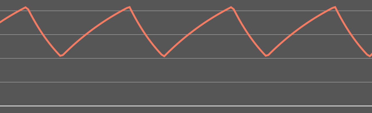
A Graph of the Capacitor Voltage in a 555 Oscillator

A Graph of the Output Voltage in a 555 Oscillator
There are several ways to graph electricity. One of the most common ways is to plot time on the x-axis and voltage on the y-axis. This gives a visible representation of how the voltage is varying within the circuit. Now, because each point on a circuit has a different voltage, you have to specify which point on the circuit you are graphing. For instance, if you take the 555 oscillator circuit from Chapter 18 (i.e., Figure 18-2), the two places whose voltages you might want to graph are (a) right before the capacitor and (b) right after the output pin.
These will give very different graphs, but both of them are instructive. The graph of (a) will show you what the input side of the circuit looks like, and the graph of (b) will show you what the output side of the circuit looks like.
Notice that Figure 19-1 changes fairly smoothly (except when it changes directions). This is because capacitor charging causes the voltageto change smoothly over time. It charges up until it reaches  ofsupply voltage and then discharges down to
  of supply voltage. It does this over and over again as you can see on the graph.
The output, however, is either on or off. Therefore, Figure 19-2 shows a very jagged graph. This is known as a square wave , because it is basically rectangular. The voltage just goes from zero to the target voltage almost instantly, and then after it stays there a bit, the voltage goes back down again just as instantaneously as it rose.
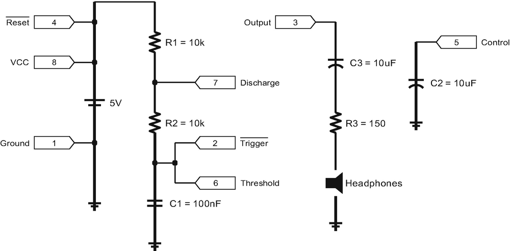
Schematic for a Simple 555-Based Tone Generator
Special devices known as oscilloscopes can be used to measure voltage changes over time. Graphs such as those in Figures 19-1 and 19-2 can be made by hooking up an oscilloscope to the circuit while it is in operation.1 Oscilloscopes used to cost thousands of dollars, but now you can pick up a small handheld oscilloscope for under $50.
Usage of an oscilloscope is outside the scope of this book, but the basics are simple enough. An oscilloscope usually has an active probe and a ground probe. You hook up the ground probe to the ground on your circuit, and you hook up the active probe to the point on the circuit that you want to measure. Then, you look at the screen, and it will graph for you what the voltage is at that point over a period of time. Most oscilloscopes have all sorts of adjustments, such as how wide of a voltage range you want to measure and how long of a time window you want to show on the screen. In any case, oscilloscopes provide graphical views of oscillating voltages.
19.3 Outputting a Tone to Headphones
In this section, we are going to modify the circuit in Figure 18-2 to add in a headphone output. Figure 19-3 shows the final circuit, and Figure 19-4 shows how to build it. This circuit has several changes to our original circuit that we will discuss in this section.
The first changes to this circuit are to the RC time circuit. Because we want the circuit to be in audio range, we are making a much higher frequency (i.e., a shorter period). To do this, we swapped out the electrolytic capacitor for a ceramic disk capacitor of 100 nF. Then, we dropped the resistors down to 10 kΩ each. This will make a tone with a period of 0.003 seconds. Taking the reciprocal gives us a frequency of about 333 Hz. This is well within hearing range for most people. You can adjust the resistors and capacitors how you wish for different tone frequencies. We are merely using the equations from Chapter 18 to determine the period and frequency.
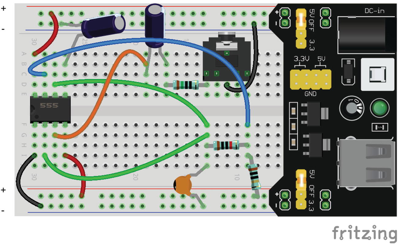
Breadboard Layout for a 555-Based Tone Generator
19.4 AC vs. DC
In Chapter 3, we introduced the ideas of direct current (DC) and alternating current (AC). In DC circuits, the circuit has a more-or-less constant voltage. Our power supply is at a certain voltage, our output is at a certain voltage, and so on. In AC circuits, however, the voltage oscillates back and forth. These oscillations introduce a whole new set of considerations.
In pure AC circuits, voltage and current actually swing both to positive and negative values. What is a negative current? A negative current happens when the electricity flows in the opposite direction. Thus, in a pure AC circuit, electricity flows back and forth, switching between directions while it is running, spending about even time in each direction.
Some components, such as speakers, assume that they are going to receive or process pure ACs. That is, they expect the current to switch direction at some point. As mentioned earlier, the speaker is driven by changing voltages in a coil, which alters the attraction of the coil to a magnet. These variations in attraction and repulsion move the coil back and forth, which moves the speaker cone, which vibrates the air, which vibrates your eardrum, which you hear. Speakers expect the oscillating current to go back and forth each direction about evenly.
However, in our circuit, the voltage only swings between a positive voltage and 0 V. If you look at the graph in Figure 19-2, notice that while the voltage goes up to a positive voltage, the lowest that it ever goes is zero. Therefore, it is not a pure AC circuit, because it is not centered around 0 V. Instead, the AC has a DC bias voltage . That is, the output voltage can be thought of as a combination of an AC voltage signal added to a DC voltage.
19.5 Using Capacitors to Separate AC and DC Components
Sometimes having a DC bias is good, and sometimes we need to separate out our AC and DC signals. Capacitors are excellent at this. Capacitors are said to allow AC to flow and to block DC. This is a simplistic view, and we will get a little more nuanced in future chapters, but it works for now.
To understand why this happens, let’s remember what a capacitor does physically. It stores charge—like a small battery. Remember, even though the pathway between the plates of a capacitor is blocked, when a positive charge accumulates on one side, it pulls electrons onto the other side, which means that the other side beyond the capacitor gets more positive as well. Do you remember what happens when the capacitor first starts charging? The capacitor basically acts as a short circuit. As the capacitor fills up, it starts acting more and more like a resistor, preventing current from flowing.
Thus, when given a constant voltage, once the capacitor is nearly full, it essentially stops getting more charge (or comes very close to it). Therefore, once it is full, it is basically blocking any more current from flowing. Since what goes onto one side of the capacitor affects what is on the other side, this same blockage will block the transmission of the current to the other side as well. Thus, in the long run, if you have a DC voltage, the capacitor will eventually block current flow. Thus, the current on the other side of the capacitor will be zero.
However, now consider what happens if the voltage changes. If the voltage changes, then the capacitor will allow current to flow through. If the voltage goes up, then the capacitor has more storage available (since the amount of storage depends on voltage). While it is charging to the new level, current will be flowing. If the voltage goes down, then the capacitor will actually have to discharge back into the circuit.
Now, if the capacitor discharges back into the circuit, which way is the current flowing? Well, that means the current from the capacitor is now flowing in the opposite direction!
Thus, what ends up happening is that the capacitor winds up only sending changes in voltage to the other side of the circuit! While the capacitor is charging and discharging, charge is moving through both sides of the capacitor. Thus, when the voltage (and therefore the charge) on the capacitor is changing, current is indeed flowing. Now, when the voltage stays the same, no electrons move, no matter what the voltage is. Therefore, even though you have a positive voltage on one side, if the voltage is not changing, no current is flowing. Therefore, on an unchanging current, the voltage on the other side of the capacitor will be zero.
Since the changes go up and down, but the DC bias voltage does not go up and down, this has the effect of sending AC through the capacitor, but blocking the DC bias voltage.
Therefore, capacitors are often used in series in a circuit to couple together parts of the circuit that are pure AC with other parts of the circuit that have a DC bias. Since the output of the 555 is DC biased and speakers generally are optimized for pure AC output, the capacitor in our output circuit filters out the DC bias and gives a pure AC signal.
A capacitor used in this way is known as a coupling capacitor .
Alternatively , if for some reason you wanted only the DC component, you could wire the capacitor to go to ground. This sends the AC part of the signal to ground, leaving only the DC component in the circuit. In such a scenario, the capacitor is being used as a filter capacitor .
Now, using a coupling capacitor does add in a small amount of distortion, both because DC bias voltage does have some effect on the signal and because different capacitor values are optimal for coupling different frequencies. For audio applications, a capacitor somewhere between 10 nF and 10 μF should be used.
19.6 Speaker Wattage
Next in the circuit is the R3 resistor. The R3 resistor is there to limit the output signal to the headphones. Headphones and speakers are all a little strange—there is very little standardization. Different headphones have different resistances in the speakers and different tolerances for how much wattage can be put through them. Speakers are usually rated by (a) how much resistance they normally add to the circuit, (b) how loud they are at a given wattage of power, and (c) what their maximum wattage is. Even though there is quite a bit of variance, for headphones, you can be fairly safe by estimating that the headphones will act as 16 Ω resistors and that they can consume a maximum of 20 mW.
The output of the 555 timer is 1.7 V less than my supply voltage. So, for a 5 V source, the output will be 3.2 V. However, since we have now centered it on 0 V, the output will actually only be half of that—1.6 V. We can usethe formula  from Chapter 10 to determine how many watts this will supply. If the speaker is 16 Ω, then the power used by the headphonewithout the extra resistor will be
  = 0.16 W = 160 mW. Therefore, the R3 resistor pulls out some of that power.
With the resistor, the combined power usage of the resistor and the headphone speaker is 166 Ω. Therefore, the power here is  = 0.015 W = 15 mW. Remember, though, that this is the combined power of both the resistor and our speaker. The speaker is only supplying about
  of the resistance, so it is only using up to
  of the power, or 1.5 mW.
Now, the calculation for this is relatively easy because we are working with square waves. The calculation becomes harder for different types of output, because you have to take into account the shape of the wave. However, we won’t go into that in this book. This calculation using the peak voltage provides a simple method which will give you a good starting point, and you can judge for yourself if you need more or less resistance for your own circuits.
19.7 Sound Control
Now, as I mentioned, all headphones are different, and, with the exception of having a coupling capacitor, they all have different ranges and need different amounts of power. Usually this is accommodated by having a volume control.
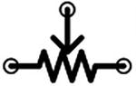
The Potentiometer Symbol
The Potentiometer as a Voltage Divider
To use a variable resistor, you would need to find one with the right range of values and then simply replace the output resistor R3 with your variable resistor.
A more common type of component which can be used as a variable resistor is a potentiometer. A potentiometer is basically a variable voltage divider. The symbol for the potentiometer is shown in Figure 19-5. It has three leads—input, ground, and output. When you turn the knob, it adjusts the relative resistance of each side of the voltage divider to vary what is coming out of the output.
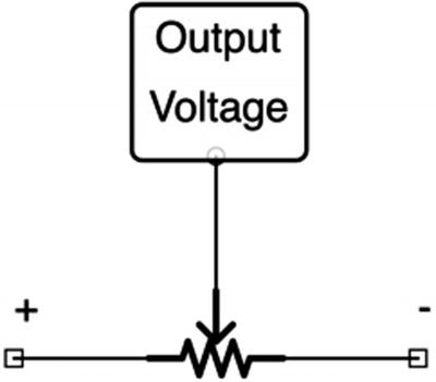
Potentiometers were built for working as a variable voltage divider. Figure 19-6 shows what this looks like. Essentially, the user controls a knob which alters the voltage coming out by changing the voltage division between the resistors.
However, you can also use a potentiometer as a simple variable resistor by just hooking up one side of the potentiometer. Figure 19-7 shows this configuration.
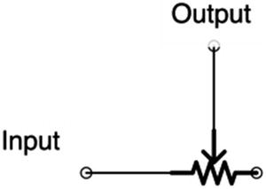
The Potentiometer as a Variable Resistor
19.8 Review
- 1.
Sound is the result of oscillations in the air that is picked up by your eardrums.
- 2.
Sound can be generated by an oscillating speaker cone vibrating against the air.
- 3.
The oscillations in a speaker cone are made by a magnet being drawn and repelled to another magnet by oscillations in electrical power.
- 4.
Sound generally has higher frequencies (i.e., shorter periods) than what we use for flashing lights.
- 5.
Audible sound frequencies range from 20 Hz to 20 kHz.
- 6.
On circuits where voltage and/or current changes with time, it is often helpful to plot their changes at specific points on a graph to help visualize what is happening.
- 7.
The output of the 555 timer is known as a square wave because it has steep changes in voltage at specific points, making a rectangular-shaped graph.
- 8.
An oscilloscope can be used to measure and record these types of graphs.
- 9.
Voltages that oscillate quickly with time are known as alternating current or AC voltages.
- 10.
Oscillating voltages that do not spend roughly equal amounts of time on either side of 0 volt are said to have a DC bias voltage.
- 11.
The DC bias voltage is how much voltage you would have to subtract from the voltage in order for the voltage to be centered on 0 volt.
- 12.
Most circuits have DC bias voltages, but most output devices (such as speakers) need the DC bias voltage removed and only use the AC component of the signal.
- 13.
DC bias voltage can be removed by placing a coupling capacitor in series with the output signal. The capacitor will only transmit voltage changes, thus removing the DC bias voltage.
- 14.
Speakers and headphones vary considerably in their properties.
- 15.
The most important considerations are how many ohms of resistance they have and how many watts are needed to drive the sound.
- 16.
For headphones, a good starting assumption is that the speaker is 16 Ω and needs under 20 mW of output.
- 17.
If your output signal is larger than this, be sure to add a resistor in series to consume some of the output signal’s power.
- 18.
The output resistor can be replaced with a variable resistor or a potentiometer to have a user-controlled output setting, also known as a volume control.
- 19.
A potentiometer is a variable voltage divider. However, by using only the positive and output terminals, it can be used as a variable resistor instead.
19.9 Apply What You Have Learned
- 1.
Why is the input voltage signal to the 555 timer smooth, but the output is square?
- 2.
Will increasing the resistance of R1 and R2 make the pitch higher or lower?
- 3.
Can you think of a way to modify the circuit so that the pitch of the sound can be adjusted while the circuit is on?
- 4.
Given the circuit in Figure 19-3, what power would be delivered to your headphones if you were using an 8 Ω speaker instead of the 16 Ω speaker? What about a 100 Ω speaker?
- 5.
The frequency of the A note above middle-C on the piano is 440 Hz. Design a modification to this circuit that will yield this frequency.
- 6.
The output of the 555 is 1.7 V less than the power supply used. What is the effect on the wattage to the headphones if we change the power supply to be a 9 V power?