
Amplification is the conversion of a low-power signal to a higher-power signal. Normally when we think of amplification, we think of sound amplifiers for musical instruments. Indeed those are amplifiers, and we will build a sound amplifier later in this book. However, anytime you convert a low-power input to a higher-power output, you have amplified the signal, whether that was a DC signal or an AC signal. In this chapter, we will focus on amplifying DC signals.
Many devices have limits to the amount of power they can output or even the amount of power we want them to output. Microcontrollers, for instance, are generally very sensitive with the amount of power they can source. The ATmega328/P (used in the Arduino Uno), for instance, has a maximum current rating of 40 mA, which is actually quite generous for a microcontroller. Other types of microcontrollers, such as many PIC microcontrollers, are rated for current outputs of 25 mA or less. Additionally, the voltage is more or less fixed at the operating voltage of the chip, which is usually 3–5 V.
However, numerous applications require more output (whether current, voltage, or power) than these can provide. A typical toy DC motor, for instance, needs about 250 mA for operation. So, if you want to control the motor with a microcontroller, then you have to have some way to convert your small output current into a larger output current to drive your motor.
Another scenario to consider is a situation where we want to control a high-power motor or another device from a button or switch. Sometimes it can be problematic to have a switch for a device to have high power run through it. It could be dangerous, or it could cost money. Let’s say that we had a switch that we wanted to control a high-power device that was 1,000 feet away. If we had the full power running through the switch, that means that we have to run larger cables and will have to account for the large resistance in the wires. Running power across that distance will result in power loss because of the resistance in the wires, which will increase the cost for running the unit! However, if we instead use a low-power circuit to run the switch, we don’t get nearly as much power loss. We just need to amplify the power output of the switch to control our device once the signal reaches it. The amount of amplification that occurs is known as the gain of an amplifier.
24.1 An Amplification Parable
As we noted in Chapter 10, physics tells us that we can’t actually increase the power of something. What we can do, though, is use a smaller power signal to control a larger power source, and that is what we refer to as amplification.
Let’s say that we have a dam on a river. The river wants to go downstream, but it is blocked by the dam. Let’s say that we have a giant named Andre, which is able to lift the dam using his strength. If Andre lifts the dam a little bit, a little bit of water flows. If Andre lifts the dam a lot, all of the water can flow. The power of the water itself is actually more than Andre’s power. Therefore, Andre can “amplify” his power by raising and lowering the dam.
Let’s say that at the end of the riverbed was a structure that Andre wanted to destroy, but Andre himself isn’t strong enough to do it. However, the river is strong enough to do it. Therefore, rather than try to destroy the structure on his own, Andre decides to raise the dam and let the river’s power do it.
Note that Andre didn’t actually increase the amount of power in the river. Instead, he (a being with lesser power) controlled the operation of the river (a higher-powered entity) by adjusting the dam (the physical resistance against the water). Thus, he amplified the effects of his actions by controlling the resistance on the higher-powered current.
24.2 Amplifying with Transistors
A very common method of amplifying power output in projects is with transistors . The term “transistor” is short for “transconductance varistor,” which means that it is an electrically controlled variable resistor. In other words, it helps you amplify a signal in your project the same way that the dam allowed Andre to amplify his power. The transistor operates as a controllable electric dam, allowing a smaller-powered electric signal to control a higher-powered electric signal by adjusting resistance.
Another way you can think of it is like an outdoor faucet—the water going through the faucet is controlled by the wheel knob on the top, which provides a variable amount of resistance to the flow. The faucet can be fully on, fully off, or somewhere in between, all based on where the knob is set. The knob setting is like the input current—a specific level of input current will control the amount of flow that comes out.
There are many different types of transistors, with a wide variety of ways in which they work. What they all have in common is that they have three (sometimes four) terminals, and one of the terminals acts as a control valve for the flow of electricity between the other two.
The main way that the types of transistors differ is in whether the knob on the faucet is controlled by voltage or by current. The transistors operated by current are known as bipolar junction transistors (BJTs), and the ones operated by voltage are known as field effect transistors (FETs).
The Schematic Symbol for a Transistor
BJTs come in two basic forms based on whether the knob is normally closed but turned on by positive current (an NPN transistor) or whether the knob is normally open but closed off by positive current (a PNP transistor). Here we will focus on NPN transistors.
24.3 Parts of the BJT
A BJT has three terminals—the collector, the base, and the emitter. In BJT NPN transistors, a small positive current comes in at the base (which you can think of as the knob of a faucet), and it controls the current moving from the collector to the emitter. The more current that comes through the base, the more current is allowed to flow between the collector and the emitter.
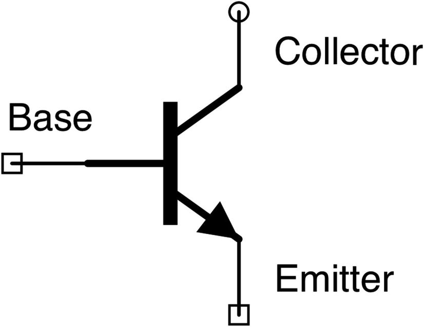
Figure 24-1 shows what an NPN BJT looks like in a schematic. The collector is at the top right of this diagram. The emitter is the line with the arrow pointing out. The current being controlled is the current between the collector and the emitter. The base is the horizontal line coming into the middle of the transistor. The base acts as a knob which can limit the flow of current between the collector and emitter.
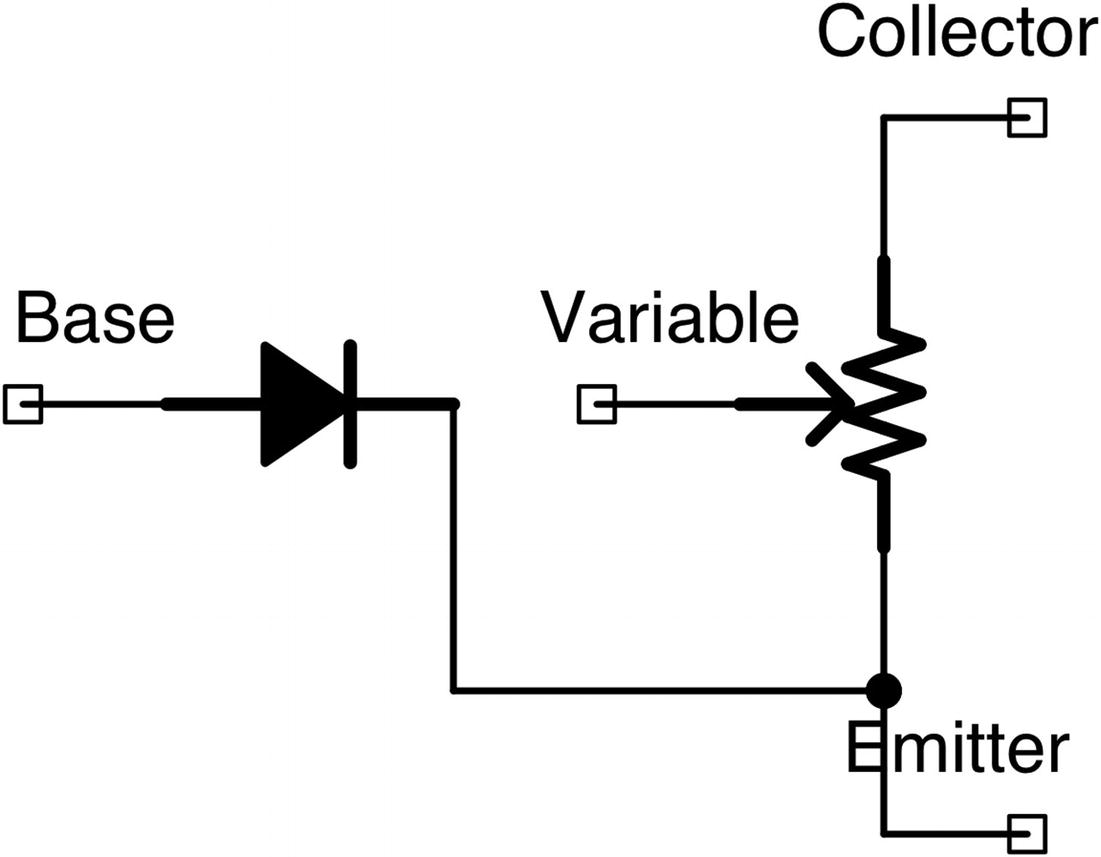
A Conceptual View of Transistor Operation
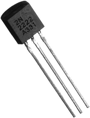
A 2N2222A Transistor in a TO-92 Package
When we talk about the voltages and currents flowing through the resistor, there are special names you need to remember and keep in mind. Each of the legs of the transistor is named by the first letter of its role. The collector is C, the emitter is E, and the base is B. Then, each of the voltages/currents is labeled based on which leg it is going from and to. Therefore, VBE is the voltage difference between the base and the emitter, VCE is the voltage difference between the collector and the emitter, and VCB is the voltage difference between the collector and the base. IBE is the current flowing between the base and the emitter, and ICE is the current flowing between the collector and the emitter. The total current coming out of the emitter is IBE + ICE. Take time to think about these designations as we are going to be using them extensively when we talk about transistors and their usage in a circuit.
A photo of a transistor can be seen in Figure 24-3. This is the transistor we will focus on in this chapter—the 2N2222A (sometimes called the PN2222A). It is important to read the datasheet to find out information about your transistor—especially to know which transistor leg is which! For the picture in Figure 24-3, the collector is on the right, the base is in the middle, and the emitter is on the left. Note that some other transistors have different pin configurations, which is why it is so important to check the datasheets. For instance, the P2N2222A (very similar name!) has the collector and emitter pins reversed!
Transistors can also come in a variety of shapes and sizes, known as packages . The package depicted in Figure 24-3 is known as a TO-92 package. Other packages you might see are a TO-18 package (which looks like a tiny metal cylinder) or a package similar to an integrated circuit.
24.4 NPN Transistor Operation Basics
To fully understand NPN transistor operation requires a lot of complicated mathematics. However, you can get a “good enough” understanding of it just by remembering a few simple rules.
Rule 1: The Transistor Is Off by Default
By default, if there is no current flowing in the base, there will be no current flowing from the collector to the emitter. NPN transistors default to an “off” state.
Rule 2: VBE Needs to Be 0.6 V to Turn the Transistor On
Remember that there is essentially a diode connecting the base to the emitter. Diodes have a voltage drop of about 0.6 V. Therefore, once the base voltage rises to 0.6 V above the emitter voltage, the transistor will turn on, and current will start to flow.
Rule 3: VBE Will Always Be Exactly 0.6 V When the Transistor Is On
This is a corollary of the previous rule. Remember from Chapter 8 that we used diodes to give us fixed voltage differences between points on a circuit. This is the same in a transistor. Because the BE junction acts as a diode, the base will always be 0.6 V above the emitter while the transistor is turned on.
Rule 4: The Collector Should Always Be More Positive Than the Emitter
While technically you can have the collector go below the voltage of the base or the emitter, it is generally a bad idea with NPN transistors. It makes the circuit much harder to analyze. This book will assume that the circuit is set up in this manner.
Rule 5: When the Transistor Is On, ICE Is a Linear Amplification of IBE
So, when the transistor is on, the transistor amplifies the current flowing from the base to the emitter by adjusting the floodgates between the collector and the emitter. The multiplier that the transistor amplifies by is known as the transistor’s beta—this is the current gain that an NPN transistor provides. The symbol for this value can be either β or hFE. The problem with a transistor’s beta is that it isn’t very exact or very constant. A batch of “identical” transistors can have betas that vary quite a bit. And, while they are operating, their temperature and other environmental factors will affect the beta as well. There are things you can do to compensate for this, but for now just realize that it happens. While there are transistors with a wide variety of ranges of their betas, the most common NPN transistors have a beta of around 100.
The exceptions to this are in Rules 6 and 7.
Rule 6: The Transistor Cannot Amplify More Than the Collector Can Supply
Using a Switch at the Start of a Circuit
Using a Switch at the End of a Circuit
Rule 7: If the Base Voltage Is Greater Than the Collector Voltage, the Transistor Is Saturated
If the base voltage rises above the collector voltage, this causes the transistor to behave as if there was no resistance going from the collector to the emitter. This is known as saturation mode .
Using these rules, thinking about transistor action is fairly straightforward. In the next section, we are going to put these rules into practice.
24.5 The Transistor as a Switch
One of the issues with transistors is that it takes a while before using a transistor becomes intuitive. Transistors, as we will see in the forthcoming chapters, wind up needing a lot of special considerations. Because of this, many people don’t use transistors directly and instead choose to only use integrated circuits (see Chapter 11). Integrated circuits, since they are based on the needs of a circuit instead of simple physical properties, tend to be much easier to work with. Most of the guess work has been taken out, and the chips are built so that they can be inserted into a circuit in a straightforward way. Even though some people opt to use integrated circuits instead of using transistors directly, it is worthwhile to understand their operation. It is always better to choose an option because you understand your available alternatives instead of choosing an option because that choice is the only one you understand.
Using a Transistor as a Switch for a Motor
When using transistors as a switch, we almost always place them at the end of a circuit. The reason for this should become clear as we examine circuits.
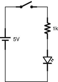
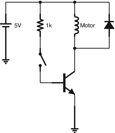
The first circuit we will look at is Figure 24-6. In this circuit, there is no real need for a transistor—we could just as easily have put the switch where the transistor is. However, understanding how this setup works will help us understand other transistor circuits. In this circuit, the base is controlled by a small signal (the size of the signal is set by the size of the resistor). When the base turns on, it switches on the connection from the collector to the emitter, which controls current to the motor (the diode is simply a snubber diode as described in Chapter 20).
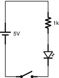
If you wanted to see inductive kick in action, you can replace the snubber in the circuit in Figure 24-6 with an LED. Every time you turn of the switch, the LED will light up for a moment.
If the emitter of a transistor is simply connected directly to ground as it is in this example, the easiest way to analyze the circuit is by looking at the flow of current through the base. When the switch is closed, current will flow from the voltage source, through the resistor, across the transistor to ground. How much current? Well, this is actually a simple question. Remember that the junction from the base to the emitter can be treated as a simple diode (Rules 2 and 3). Therefore, we have a very simple circuit to analyze—voltage source to resistor to diode to ground. The voltage source is 5 V, and we have a diode (0.6 V) in the circuit path, so the voltage going through the resistor will be 4.4 V. Since the resistor is a 1 kΩ resistor, then, using Ohm’s law, the current will be  , or 4.4 mA.
Since the current going through the base (IBE) is 4.4 mA, how much current is flowing from the collector to the emitter? We will assume for our exercises that the beta of transistors is exactly 100. According to Rule 5, that means that the current going from the collector to the emitter is 100 times the base current. Therefore, the current going from the collector to the emitter can be determined by ICE = β⋅IBE = 100⋅4.4 = 440mA. Therefore, the current going from the collector to the emitter is 440 mA. Because the current at the collector is 440 mA, that means that the current going through the motor is also 440 mA.
Depending on the current we wanted flowing through the motor, we could choose other resistor values to set the current to the appropriate level. However, because of Rule 6, the collector current will be limited by the motor’s characteristics as well.
So why did we put the transistor at the end of the circuit? Let’s imagine that we added one component to the circuit—a resistor after the emitter before the ground. All of a sudden, the circuit is a lot harder to analyze. Why? Well, we can no longer determine the base current by simply looking at the current path through the base. The voltage across that final resistor will not be based on the base current, but based on the combined current from both the base and the collector. Thus, when there are components after the emitter, in order to analyze the base current, you have to analyze how the components after the base respond to the combined current of the base and collector, but we won’t know that until after you calculate the base current. It is possible to do this, but the math isn’t fun. Instead, by connecting the emitter directly to ground, we simplify our calculations because we know the voltage after the emitter—since it is connected to ground, it will be zero.
Thus, by connecting the emitter directly to ground, we can analyze the current flow from the base independently of the current flow from the collector. Additionally, connecting the emitter to ground will automatically make sure our DC circuits follow Rule 4 and make it easy to analyze when the transistor turns on and off by Rule 2.
Just as we have looked at several common resistor circuit patterns, there are also several common transistor circuit patterns. The transistor pattern we are looking at in this chapter is known as a common emitter circuit. This is because the “interesting” parts of the circuit are at the base (which provides the current to be amplified) and the collector (where the preceding circuit enjoyed the amplified current) and the emitter is connected to a common reference point (the ground in this case).
24.6 Connecting a Transistor to an Arduino Output
To understand why we would use a transistor for a switch in the first place, let’s imagine that we have a motor just like in Figure 24-6, but in this case we want it to be controlled by an output pin from an Arduino running on an ATmega328/P.
Now, on this chip, output pins put out 5 V, but their current rating maxes out at 40 mA. However, motors usually require much more current than that. If we wanted our motor to use as much current as in Figure 24-6, it would blow out the chip if we tried to connect it directly to the output.
However, we can instead wire the output of the Arduino to the base of a transistor. Then, the current coming out of the Arduino will be much smaller than the current used by the motor.
 , then
  . With a beta of 100, that means that our motor can source 440 mA.
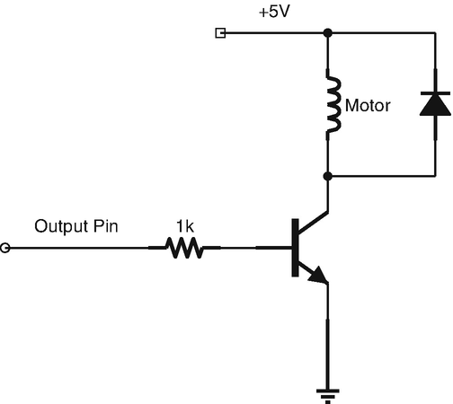
Using a Transistor to Control a Motor with a Microcontroller
24.7 Stabilizing Transistor Beta With a Feedback Resistor
As we mentioned earlier, the transistor’s beta is not a very stable parameter. If we mass-produced something with a transistor, each device would wind up having a transistor with a different beta. Additionally, as the device was used, the beta would drift, meaning that things such as the temperature of the transistor would affect the beta, so it wouldn’t even have the same value the entire time it was turned on!
In order to get around this, engineers have developed ways of stabilizing the actual gain of a circuit even when the transistor’s beta shifts. The way that this is achieved depends greatly on the type of circuit used. In a common emitter circuit like the one we have been looking at in this chapter, we can add a resistor to the emitter to stabilize the transistor’s gain. I know that I just said not to do this because it is hard to analyze the effects. However, if you add a single resistor to the emitter, other people have worked out the math for you in order to make this work easily.
Now, to imagine why adding a resistor to the output stabilizes the transistor beta, we have to think about what happens when you do this. Without the resistor, when the transistor beta increases, it simply increases the current flow at the collector. Since the emitter is connected to ground, there aren’t any more real effects. However, if I add a resistor to the emitter, then increasing the current flow at the collector will also increase the voltage at the emitter. Now, since the voltage between the base and the emitter (VBE) must be at 0.6 V, this will actually reduce the current in the base.
This is known as feedback—where the output of the circuit comes back in some way to affect the input. Sometimes, feedback occurs because the output is wired back to the input, but in this case, the resistor simply increases the voltage at the emitter, causing the base to pull back.
What the final effect of adding a resistor to the base will do is to limit the gain of the transistor to a fixed value that won’t change either due to manufacturing issues or due to changes during operation as the transistor beta changes due to temperature. Additionally, the computation for this is very simple. If your transistor beta varies between 50 and 200, you can add a resistor to the emitter which will limit the actual transistor gain below 50, and it will keep this value very stable even as the transistor’s beta drifts. In such a configuration, the most stable gain you can get for a given transistor beta is about  of the transistor’s lowest beta.
The equation for the effect that a feedback resistor has on a transistor circuit depends on the circuit design itself—there isn’t a one-size-fits-all rule. However, feedback resistors are usually fairly small compared to the rest of the circuit.
For most circuits, simply start with a small feedback resistor (10–100 Ω). The feedback resistor will usually improve the stability of your design, even if you can’t calculate exactly how that affects the beta of the transistor. It means that your design will likely continue to work even with different transistors and operating at different temperatures. Just know that while you add stability, this will also limit the gain (which is sometimes problematic with motors).
24.8 A Word of Caution
One thing to keep in mind with transistors is that they can get very hot! Transistors have a maximum current rating, and that often is based on the amount of heat that they are able to dissipate. Transistors that are able to handle large currents are called power transistors , and usually have an attachment for a heatsink, which helps them dissipate heat to the air more efficiently.
If you build a circuit similar to the one in this chapter, be sure to keep in mind both the specs of the motor (how much voltage and current is required for it to operate) and the specs of the transistor (how much current the transistor can handle). If the motor doesn’t have enough voltage or current, it might not turn on, and if the transistor can’t handle the current, it could easily burn out.
Review
In this chapter, we learned the following:
- 1.
It is often beneficial to be able to control a high-power signal using a low-power signal.
- 2.
The two major types of transistors are bipolar junction transistors (BJTs) and field effect transistors (FETs).
- 3.
BJTs are current-controlled devices and FETs are voltage-controlled devices.
- 4.
The terminals of a BJT are the base (B), the collector (C), and the emitter (E).
- 5.
Voltages and currents going through a transistor are labeled using the terminals that the current is passing through. For instance, IBE refers to the current flowing between the base (B) and the emitter (E), and VCE refers to the voltage difference between the collector (C) and the emitter (E).
- 6.
BJTs come in two main configurations—NPN and PNP.
- 7.
With NPN transistors, a small positive current at the base causes a larger current to flow from the collector to the emitter.
- 8.
With PNP transistors, current at the base reduces the current flow from collector to the emitter.
- 9.NPN transistors can be analyzed using these seven rules:
The transistor is off by default.
VBE needs to be 0.6 V to turn the transistor on.
VBE will always be exactly 0.6 V while the transistor is turned on.
The collector should always be more positive than the emitter.
When the transistor is on, ICE is a linear amplification of IBE.
The transistor cannot amplify more than the collector can supply.
If the base voltage is greater than the collector voltage, the transistor is saturated (it will offer no resistance from the collector to the emitter).
- 10.
The amount of current amplification a transistor provides is known as the transistor’s beta (also known as β or hFE).
- 11.
The actual beta of a transistor is not very stable and fluctuates quite a bit both because of manufacturing differences between transistors and even within a single transistor due to environmental changes such as temperature.
- 12.
When used as a switch, transistors are usually placed at the end of a circuit in order to make the circuit analysis easier.
- 13.
Transistors are often used to couple the outputs of devices with low current limits (such as a microcontroller) with devices that require higher output currents (such as motors).
- 14.
To stabilize a transistor circuit’s gain so that it doesn’t vary with the transistor’s beta, you can add in a small emitter resistor.
Apply What You Have Learned
- 1.
If the base of a transistor is at 3 V and the transistor is on, what will be the emitter voltage?
- 2.
If the base of a transistor is at 45 V and the emitter is on, what will be the emitter voltage?
- 3.
If the base of a transistor is at 5 V and the emitter, if conducting, would have to be at 4.5 V, is the transistor on or off?
- 4.
If the base of a transistor is at 0.6 V and the emitter is at ground, is the transistor on or off?
- 5.
If the base of a transistor is at 0.4 V and the emitter is at ground, is the transistor on or off?
- 6.
If a transistor has a base current (IBE) of 2 mA and the transistor has a beta of 55, how much current is going through the collector (ICE)?
- 7.
In the previous problem, how much total current is coming out of the emitter?
- 8.
If a transistor has a base current of 3 mA and the transistor has a beta of 200, how much current is going through the collector?
- 9.
If the base voltage is greater than the collector voltage, what does this mean for our transistor operation?
- 10.
The output of your microcontroller is 3.3 V and supports a maximum output current of 10 mA. Using Figure 24-7 as a guide, design a circuit to control a motor that requires 80 mA to operate. Assume that the transistor beta is 100.
- 11.
Redesign the previous circuit so that it utilizes a stabilizing resistor on the emitter to prevent variations in the transistor beta.