
We will end our discussion of amplification by discussing partial circuits. Oftentimes you will need to design a circuit which connects to another circuit, either powering it or receiving power from it. For instance, in the amplification circuits from Chapter 25, the outputs were connected to a speaker. They could also be connected to another amplifier or to a stomp box (a device to modulate the incoming signal in some way) or to a recording circuit.
26.1 The Need for a Model
In order to connect circuits together, we need to be able to describe, in general terms, the ways that circuits fit together. When dealing with transistors and other power amplification devices, we often need to come up with a simplified model for how the input to a circuit or the output from a circuit behaves. Early on (in Chapter 7), we learned how to take multiple resistors in series and parallel and combine them into an equivalent single resistor.
When dealing with a power amplification circuit, it is often necessary to look at various parts of the circuit by themselves and figure out how they look to other parts of the circuit. The way that a partial circuit looks to other parts of the circuit is called the circuit’s Thévenin equivalent circuit .
A single voltage source (AC, DC, or DC-biased AC, expressed in RMS voltage)
A single impedance (i.e., resistance) in series with the voltage source
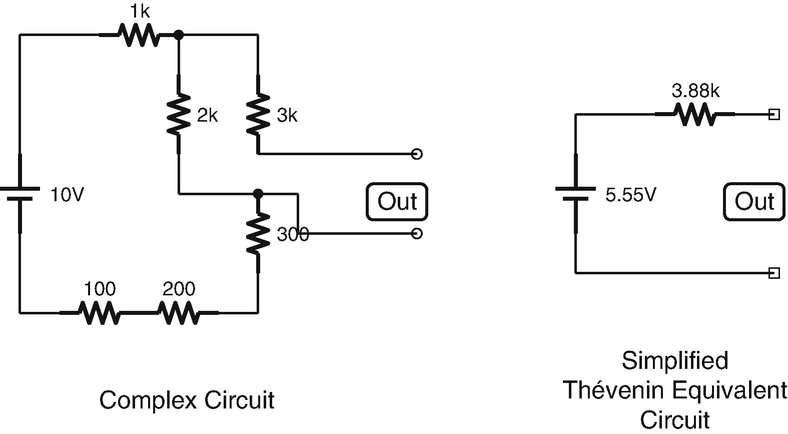
A Complicated Circuit and Its Thévenin Equivalent Circuit
Figure 26-1 shows a circuit and its Thévenin equivalent circuit . For purposes of thinking about and understanding the relationship between the circuit and things attached to the circuit, we can view the circuit as being the same as its Thévenin equivalent. Thus, having a Thévenin equivalent circuit greatly simplifies our modeling, calculating, and understanding of how circuits work together.
Any network of power sources and resistances can be converted into a Thévenin equivalent circuit. You can also get a Thévenin equivalent circuit for a circuit that includes capacitors and inductors, but the calculations become more difficult and the results are only valid for a specific frequency (each frequency will have a different Thévenin equivalent circuit). For simplicity, we will just focus on resistive circuits.
26.2 Calculating Thévenin Equivalent Values
To see how to calculate the voltage and resistance for a Thévenin equivalent circuit, this section will take a classic voltage divider circuit and analyze how it “looks” to other attached circuits. Figure 26-2 shows an example of a partial circuit. Like most partial circuits, this circuit has two output points—A and B. What we are wanting to know is this—if we attach another circuit up to A and B, is there a model that we can use to understand how the other circuit “sees” our circuit? The goal of making a Thévenin equivalent circuit is to understand what our circuit will look like to other attached circuits.
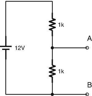
A Voltage Divider Partial Circuit

Calculating the Thévenin Resistance of the Circuit
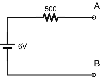
The Thévenin Equivalent of the Voltage Divider
Now we need to find our Thévenin resistance. There are multiple tricks to do this, but the simplest one is to replace all voltage sources in your circuit with a wire (i.e., a short circuit) and simply compute the total resistance between A and B.1

Therefore, we would say that this partial circuit has a Thévenin voltage of 6 V and a Thévenin resistance of 500 Ω. Whenever we attach a circuit to this circuit, what that other circuit will “see” is a circuit like the one in Figure 26-4.
If you wanted to prove this to yourself, you can imagine a variety of different circuits attached to both our original circuit and to the Thévenin equivalent circuit. You will find that, in all cases, the amount of voltage and current the Thévenin equivalent circuit provides to the other circuit is the exact same as what the original circuit will provide.
That isn’t to say that the circuits themselves are exactly equivalent. Our original voltage divider uses up a lot of current stepping down the voltage of the voltage source. Not only does that waste energy from our battery but it probably also causes a lot of heat. However, any subcircuit that gets attached to A and B will see both our original circuit and the Thévenin equivalent circuit as providing the same output.
26.3 Another Way of Calculating Thévenin Resistance
There is another way of calculating Thévenin resistance. In this method, we first calculate what the current would be if you shorted A to B directly with a wire. This is known as the short-circuit current, or ISHORT . Then, after calculating this, you can divide the Thévenin voltage by ISHORT to obtain the Thévenin resistance.
When doing this, you have to remember that anything in parallel with our short will be essentially ignored—the current will always want to go through our short circuit.
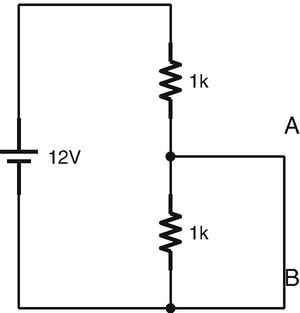
Figure 26-5 shows what this looks like. What we want to do is to calculate the current going from A to B. Since A to B is a short circuit in parallel with our second resistor, we know that all of the current will prefer the short circuit. This means that the current going through A and B will simply be the current that is limited by the first resistor.


Finding the Short Circuit Voltage
As you can see, this is the same value that we got from the previous method.
26.4 Finding the Thévenin Equivalent of an AC Circuit with Reactive Elements
If a circuit has reactive elements (inductors and capacitors), we have to do a little more work to find the Thévenin equivalent circuit.
For DC circuits, this is relatively simple. Since capacitors block DCs and inductors are a short circuit for DCs, we can simply treat the capacitors as open circuits (i.e., unconnected) and treat the inductors as short circuits (simple wires). For AC circuits, you can get a feel for what this will be by assuming the opposite—that capacitors will be short circuits and inductors will be open circuits.
However, if you were to try to solve it explicitly, the problem is a little more difficult. The problem is that a full analysis of such circuits requires math involving complex numbers (i.e., numbers involving the imaginary unit i). While the technique is roughly equivalent to adding resistances in series and parallel as we have done before, it is much more difficult to do the math with complex numbers.
For the purposes of this book, the previous statements about DC and AC should suffice for a general understanding of how your circuit works.
26.5 Using Thévenin Equivalent Descriptions
Many circuits are described to their users using Thévenin equivalent descriptions. For instance, many circuits are described by their input or output impedance. This gives you a rough guide to imagine what will happen if you connect your own circuit to such circuits.
Imagine that you have a circuit that has a Thévenin equivalent output impedance of 500 Ω. If you connect an output circuit that only has 250 Ω of resistance, what do you think that will do to the signal? Well, since the output of the circuit is equivalent to going through a 500 Ω resistor (that’s what Thévenin equivalence means), then if I connect a 250 Ω resistor, then I will have created a voltage divider in which two-thirds of the voltage will be dropped by the circuit I am connecting to and I will only get one-third of the output voltage.
On the other hand, if the impedance of my circuit is 50, 000 Ω, then the voltage drop coming out of the circuit in question is negligible compared to the voltage drop within my circuit. This means that my circuit will essentially receive the full Thévenin equivalent voltage.
We can also use this to calculate the amount of current that our circuit will draw. Let’s say that a circuit yields a Thévenin equivalent output of 4 V with an 800 Ω impedance. If I connect a 3,000 Ω output circuit, how much current will flow? The total resistance will be 3,800 Ω, so the current will be V/R = 4/3800 ≈ 1.05 mA.
Example 26.29 If I have an output circuit which is a Thévenin equivalent to 3 V RMS and 200 Ω and I connect it to a set of 16 Ω headphones, what will the power of the headphones be in watts?
We can understand this circuit as simply being a voltage source followed by two resistors in series. The voltage source will be 3 V, and the resistances will be 200 Ω and 16 Ω, totaling 216 Ω. The current will therefore be V/R = 3/216 ≈ 0.0139 A. The voltage drop in the headphones will be I ⋅ R = 0.0139 ⋅ 16 ≈ 0.222 V. Therefore the power delivered to the headphones will be V ⋅ I = 0.222 ⋅ 0.0139 ≈ 0.00309 W, or 3.09 mW.
26.6 Finding Thévenin Equivalent Circuits Experimentally
In addition to using circuit schematics to determine Thévenin equivalent circuits, it is also possible to determine them experimentally. This way, if you are unsure of the input or output characteristics of your device, you can measure it yourself. The problem with measuring it yourself is that it requires attaching a load to the circuit. Some circuits will fry if a wrongly sized load is attached. You have been warned.
The easiest way to determine Thévenin equivalency experimentally is rather unsafe, but it will help us understand better why the method works. Imagine a voltage divider where the bottom resistor has an extremely large resistance—say, 100 MΩ. In such a voltage divider, the bottom resistor will have almost the entirety of the voltage drop, right? In fact, if the bottom resistor was infinite, it would in fact have all of the voltage drop.
Because of this, we can determine the Thévenin equivalent voltage by measuring the output voltage when there is nothing connected, because no connection means that there is infinite resistance between the output and ground. Measuring this value will give us the Thévenin equivalent voltage.
Example 26.30 If I measure the open-circuit (i.e., disconnected) voltage of the output of an unknown circuit as 8 V and the short-circuit current of the output as 10 mA, what is the Thévenin equivalent circuit?
To find this out, we simply use Ohm’s law. What resistance would cause an 8 V source have 10 mA of current?

Therefore, our Thévenin equivalent circuit is 8 V with an impedance of 800 Ω.
The problem with this method is that you don’t normally want to short-circuit your output. Additionally, some circuits require some sort of a load to work properly. In order to adjust to such scenarios, there is a set of equations that allow us to measure the voltage drop across a large and small resistance (instead of infinite and no resistance) and come up with a Thévenin equivalent circuit.


Example 26.31 I have a circuit that generates an output for which I need to know its Thévenin equivalent properties. I tested the circuit with a 200 Ω resistance for my low resistance and a 1000 Ω resistance for my high resistance. With the 200 Ω resistance, there was a 2 V drop across the resistance. With the 1000 Ω resistance, there was a 5 V drop across the resistance. What is the Thévenin equivalent circuit for this circuit?
First, we find the Thévenin equivalent voltage using Equation 26.1:


Therefore, our unknown circuit has a Thévenin equivalent voltage of 8 V and a Thévenin equivalent impedance of 600 Ω.
What makes this method valuable is that it allows a way to experimentally determine the Thévenin equivalent of a partial circuit that you don’t have a schematic for or for which determining the Thévenin equivalent circuit might be difficult due to nonlinear components such as transistors.
Review
- 1.
In order to be able to connect circuits together without knowing all of the details of how they are implemented, we need a simplified model of how those circuits work with other circuits they are connected to.
- 2.
A Thévenin equivalent circuit is a combination of a single voltage source and a single series impedance which models the way that the given circuit will respond to other attached circuits.
- 3.
To calculate Thévenin equivalent voltage, calculate the voltage drop for an open circuit between the two terminals. This is the Thévenin equivalent voltage.
- 4.
To calculate Thévenin equivalent impedance, calculate the impedance from one terminal to another (or to ground if there is only one terminal), replacing any voltage sources with short circuits.
- 5.
Alternatively, to calculate Thévenin equivalent impedance, calculate the current flowing from one terminal to another if there was a short circuit between them. Then use Ohm’s law to calculate the resistance.
- 6.
Thévenin equivalent circuits can be used to understand how the resistances of attached circuits will affect the signal coming out of or into a circuit.
- 7.
Thévenin equivalent circuits can also be found experimentally.
- 8.
Although not recommended, the Thévenin equivalent voltage and resistance can be found easily by simply measuring the voltage drop of an open circuit across the terminals and the current flowing through a short circuit between the terminals.
- 9.
A better option for experimentally measuring Thévenin equivalencies is by measuring the voltage with two different load resistances across the terminals. Then the Thévenin equivalencies can be found using Equations 26.1 and 26.2.
Apply What You Have Learned
- 1.
Why would we want to know what a circuit’s Thévenin equivalent circuit is?
- 2.
What are the two components of a Thévenin equivalent circuit?
- 3.
Think about the two-stage amplifier that you built in Chapter 25. How would you go about finding the Thévenin equivalent circuit as it is seen by the headphones?
- 4.
Suppose I have a circuit where the output terminals have a 2 V drop when it is an open circuit and have 2 mA of current flowing through it when it is a short circuit. Draw the Thévenin equivalent circuit.
- 5.
If I have a Thévenin equivalent circuit of 4 V with an impedance of 400 Ω, what will be the voltage drop of the load if I attach a 2000 Ω resistor across the output?
- 6.
If I have a Thévenin equivalent circuit of 3 V with an impedance of 100 Ω, what will be the voltage drop, the current, and the power of the load if I attach headphones rated at 32 Ω?
- 7.Calculate and draw the Thévenin equivalent circuit of the following circuit:

- 8.
Suppose I have a circuit where when I add a load of 350 Ω, I get a 7 V drop and when I add a load of 2000 Ω, I get an 8 V drop. Calculate and draw the Thévenin equivalent circuit.