
Chapter 4
Store and Share – Entity Identity Structures
Abstract
This chapter contains a discussion of the different approaches for storing entity identity information in entity identity structures (EIS) and the most common architectures used in dedicated MDM systems.
Keywords
Entity identity structures; Identity knowledge base; MDM architecturesEntity Identity Information Management Strategies
A characteristic distinguishing entity identity information management (EIIM) from entity resolution (ER) is the persistence of entity identity information, including entity identifiers, from process to process. As noted in Chapter 1 and shown in Figure 1.2, the focus of basic ER or record linking is to properly classify entity references into clusters where all references in the same cluster are equivalent, i.e. refer to the same real-world entity, and are not equivalent to references in other clusters. The focus of ER is on the correct aggregation of references into clusters and the avoidance of false positive and false negative errors.
In MDM it is important to consistently identify (label) each master data entity under management over time. This requires every MDM system to implement a strategy for storing enough entity identity information so that the same master data object can be recognized and labeled with the same identifier over time. These storage structures are called entity identity structures (EIS).
Every information system of any size will have master data. Organizations using this master data must undertake some form of MDM, either implicitly or explicitly. The MDM capability and maturity of organizations varies widely from ad hoc, manually mediated MDM to sophisticated programs with dedicated MDM software and well-executed master data governance.
Bring-Your-Own-Identifier MDM
One of the earliest and perhaps still the most prevalent forms of MDM for party entities is Bring-Your-Own-Identifier (BYOI). In BYOI it is the party’s responsibility to manage their own identifier. A classic example is a company payroll system. When a new employee is hired, a master employee record (EIS) with a unique employee identifier is created and recorded in the system, typically as a row in a database table. At the time it becomes the employee’s responsibility to provide his or her employee identifier when conducting any employee-related transactions. For example, the employees may be required to clock-in and clock-out with a time card bearing their employee number in order to be properly paid.
Many colleges and universities use the same BYOI strategy by assigning each student a unique identifier upon admission. From that point on, all transactions with the school’s systems, such as course registration, computer access, and meal plans, require the student to present his or her school-assigned identifier.
BYOI MDM is most effective in a closed system where entry and exit points from the system are well-controlled and the party’s engagement occurs over a relatively long period of time. Hopefully students and employees will be engaged with the organization over a period of months and years. Although BYOI is not as practical for nonparty entities such as product entities, which can less reliably self-identify, it is not impossible. Barcode scanning and radio frequency tag identification (RFID) can allow nonparty entities to self-identify in certain situations.
It is interesting to note somewhat of a return to BYOI in recent years. This is reflected in the widespread use of customer loyalty programs where customers garner rewards for self-identifying with a card or other token. For example, most large grocery chains, clothing stores, airlines, and many other companies have extensive customer loyalty programs primarily so that customers will self-identity, thus simplifying CDI, the CRM version of MDM.
Once-and-Done MDM
In a more open system, such as a hospital or a small business, where party engagements are more frequent, a Once-and-Done (O&D) type of MDM is often employed. Here the party entities are not expected to know their own identifier. Instead, clerks or other agents of the organization make a decision at the point of entry as to whether the party already has an assigned identifier (is already under management) or whether a new identifier and identity record should be created.
This decision authority is often distributed across many different agents staffing different points of engagement with the parties. The agent’s decision is often aided by some type of “look-up” system that allows the agent to search the central registry of entities by identity attributes such as name, address, or date-of-birth. Using whatever tools are at hand, the agent makes a one-time decision on an identifier for the party at the point of engagement. This identifier, either selected by the agent from previously assigned identifiers or a newly created one, goes into the system as the identifier of record for all further processing of information related to the engagement.
Although some error correction may be done manually if discovered at a later point, O&D MDM does not use automated ER systems to do system-wide reconciliations of identifiers used by the system. The accuracy of O&D MDM depends heavily on the training and diligence of the agents. Errors in O&D MDM will accumulate over time. False positive and negative errors often accumulate to the point that a large-scale intervention is required to clean up the system. These interventions often result in a large number of entity identifier changes, a situation which works against the goal of maintaining persistent identifiers.
Dedicated MDM Systems
The movement to develop dedicated MDM software systems and master data governance began in earnest in the 1990s with the introduction of customer relationship management (CRM). Companies began to recognize customer information as master data and wanted to manage it more effectively. However, for many types of businesses, it was impractical to require customers to self-identify and, for many engagements, an agent was not always present to select an identifier. Hence, neither the BYOI nor the O&D model for MDM would be effective. Out of this dilemma was born a new kind of MDM called customer data integration (CDI). The application of ER to build customer recognition systems is the precursor of EIIM and MDM as we know them today (Dyché & Levy, 2006).
The Survivor Record Strategy
The most common EIIM strategy is simply to add one additional step to the ER merge-purge process that selects a single reference from each cluster to represent the entity. In this case the EIS is essentially the structure of the reference. The selected reference is called the survivor record because the other references are discarded after the single reference has been selected.
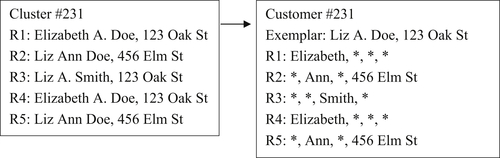
The survivor record typically has two versions, a “best record” survivor or an “exemplar record” survivor. Figure 4.1 shows an example of these two versions of the survivor record strategy.
In the best record version of the survivor strategy, user-defined rules are designed to select one reference from the cluster that is considered the best representative. What is considered a best reference will vary by application. In the example in Figure 4.1, the record R3 was selected because it has the most complete name (a full middle name instead of an initial). The problem with selecting the best record is that not all the most desirable features for a given application are always found in one reference. As in this example, even though “Liz” is the predominant (most frequent) first name value, the longer version “Elizabeth” might be preferred. In addition, the reference with the most complete name has the least frequently occurring address.
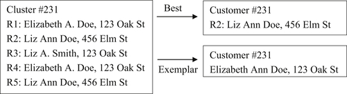
An alternate version of the survivor record strategy is to create an exemplar record. In this form the user defines a set of rules that create a single reference by assembling what are considered to be the best features from various references in the cluster. In the example given in Figure 4.1, the first name “Elizabeth” was selected because it is a full name rather than a nickname. The middle name “Ann” was selected again because it is the most complete. The last name “Doe” was selected because it is the most predominant as is the address “123 Oak St.”
The rules for both best and exemplar record strategies will vary. For example, it could be argued the value selected for the exemplar should always be based on frequency of occurrence rather than completeness. In any case, the final choice should be based on what gives the most accurate ER results.
Attribute-Based and Record-Based EIS
The problem with the survivor record strategy for EIIM is due to useful information being lost. As in the example shown in Figure 4.1, the customer has two different addresses and two different last names, but only one can be carried forward into the survivor record. To solve this problem more elaborate EIS are required to go beyond the simple survivor record strategy. Sørensen (2012) calls this “going beyond true positives in deduplication.” These generally fall into two categories: attributed-based EIS and record-based EIS.
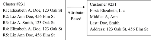
In an attribute-based EIS, the goal is to preserve the variety of values occurring for each identity attribute. In its simplest form, the EIS maintains a list of unique values for each identity attribute. Figure 4.2 illustrates the principle of the attribute-based EIS.
The attribute-based EIS is the extreme of the exemplar record because it preserves every combination of values. Because two choices of values exist for each of the four attributes, this structure provides 24 = 16 match combinations. One issue with the attribute-based EIS is that it can produce combinations of values possibly invalid for the entity. For example, it could produce a combination of a name at an address even though in reality the name was never associated with the address. Whether this presents a problem for the ER process will depend upon the nature of the data. The risk it represents is another reason why ER analytics are important to obtaining high-quality MDM results.
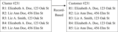
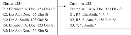
In a record-based EIS, the goal is to preserve the references comprising each entity. As the name implies, a record-based EIS preserves not only reference values, but also the record structure of the references. Figure 4.3 illustrates the principle of the record-based EIS using the same cluster as shown previously in Figure 4.1.
The record-based EIS can be thought of as the extreme of the best record version of the survivor record strategy because every record is kept intact. One issue with the record-based EIS is it often carries a lot of redundant information. For example, in Figure 4.3, only two different address values exist across all five of the references.
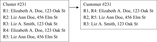
Figure 4.4 shows one method for handling record redundancy called the duplicate record filter.
With the duplicate record filter, only one copy of each unique reference is kept with either a counter or list of record identifiers to show its multiplicity. This can save storage in applications where the references with the same information are processed frequently, and it would be burdensome to keep a complete copy of every duplicate reference.
Yet another approach is the hybrid between the record-based EIS and the exemplar version of the survivor record strategy. This is illustrated in Figure 4.5.
The EIS shown in Figure 4.5 has an exemplar record built from the predominant values for each of the identity attributes and also a copy of each reference. However, for those identity attributes where the value in the reference is the same as in the exemplar record, an asterisk (∗) is used instead of the actual value. Only when the attribute value in the reference differs from the corresponding value in the exemplar record is the actual value of the attribute used in the reference.
As the structures grow more complex, to save storage there is a corresponding increase in time to manipulate the structures. For example, when a new reference is added to the EIS shown in Figure 4.5, the values in the new reference may cause a change in the predominant value for one or more attributes. If this occurs, then the exemplar and the references with that value must be adjusted appropriately.
Finally, Figure 4.6 shows a record-based EIS using both the record filter and the exemplar record.
ER Algorithms and EIS
Before leaving the topic of EIS it is important to note that the choice of EIS must be taken into consideration with other components of the MDM system. In particular, the EIS must be selected so that it will properly support the way in which match rules are applied to EIS, and support the ER algorithm that will be used for systematically comparing EIS. The interaction of EIS, matching rules, and ER algorithms is discussed in more detail in Chapter 8.
The Identity Knowledge Base
Regardless of the EIS strategy, the collection of all EIS comprises the identity knowledge base (IKB) that is the primary repository of identity information and provides a central point of management. The IKB is sometimes referred to as the central registry or the system hub. The EIIM strategies and their associated EIS, as described in the introductory portion of this chapter, represent conceptual models. The actual implementation of these models in an information system will vary widely depending upon the characteristics of the actual MDM application including its size, the type of source data, the volatility of the information, and timeliness of access.
For example, an MDM system using survivor record EIS might reside on a single database server in which the IKB is a single master table of entities. The updates and access to the information in the master table may simply be handled with SQL statements and queries. On the other hand, expansive interactive applications using record-based EIS typically reside on large-scale distributed processor architectures. In these systems, the EIS are often virtual structures in which the references reside in different tables or distributed storage folders joined on demand in order to create a complete EIS.
Storing versus Sharing
For many large-scale MDM systems, the storing and maintenance of the IKB and access to the IKB are distinct operations and sometimes use different copies of the master data (Kobayashi & Talburt, 2014a). Typically, updates happen in large batch operations in a database or distributed data architecture often not well-suited for interactive or on-demand batch access. Systems such as these typically utilize two concurrent operations: a background operation in which the information is updated, and a foreground operation that provides continuous, and often real-time, access to the information.
The illustration in Figure 4.7 shows the relation between these processes. In the background, periodic batch updates are made to IKB stored in a very large database system (VLDBS). Batch access may be provided in the background as shown here, or it may be a service provided in the foreground along with interactive access. The arrow crossing the boundary is to indicate a periodic transfer of identity information from the VLDB system to refresh the information in the distributed environment. In most systems, the foreground process is a read-only system not allowing updates to flow back to the identity knowledge base.

In other cases, the two operations operate within the same system, and rather than operating concurrently, they operate alternately, i.e. time share. For example, the background updates may occur during an overnight operation and then give way to interactive operations during the business day.
MDM Architectures
Storing and sharing strategies are closely related to the style of architecture used to implement MDM systems. MDM architectures can be described by the relationships among three principal MDM components. These components are the IKB, “source records,” and “client systems.” The IKB is the central repository or hub of the MDM system containing a single representation of each master entity under management. A source record is any record in the information system specifically referencing one of the master entities. Because these source records usually reside in various application-specific subsystems of the enterprise system, source records comprise two types of attributes: identity attributes and application-specific attributes. If the identifiers for the entities referenced by the source records in the application specific subsystem are managed by the IKB, then these subsystems are the MDM system’s clients.
MDM architectures can be classified many ways. Berson and Dubov (2011) have classified MDM architectures into four categories based on two factors. The first factor is how the attributes in the source records are partitioned between the IKB and the client systems. The second factor is the level of interaction and control the IKB exercises over its client systems. They define four types of MDM architectures: external reference style, registry style, reconciliation engine, and transaction hub.
External Reference Architecture
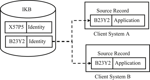
In the external reference architecture, the IKB is a large cross-reference table connecting equivalent references located in the various client systems. The EIS in the IKB are entirely virtual, only containing pointers to the references to a particular entity. None of the actual entity identity information for a particular entity is stored in the IKB.
Both the identity attribute values and the application-specific attribute values of the source record reside in the client system as shown in Figure 4.8. The advantage of external reference architecture is that changes to an entity identifier taking place in one system can be more easily propagated to all other client systems where the same entity is referenced.
The external reference architecture works best when the governance policy allows for distributed authority to make master data changes in several different client systems. It does not work as well in systems where a large number of new source records must be ingested and identified on a regular basis. In systems implementing external reference architecture, the identity information needed for matching must be marshaled on demand from the client systems where it resides.
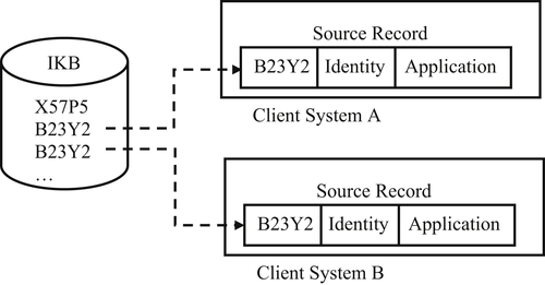
Registry Architecture
A more common architecture for MDM applications ingesting and managing large volumes of input data is registry architecture. In registry architecture each EIS in the IKB contains a collection of identity attribute values representing the entity under management. Each EIS has an identifier serving as the master identifier for the entity across all client systems. The amount of identity information retained in the EIS will vary from system to system and on the choice of EIS strategy as discussed earlier, e.g. survivor record, attribute-based, record-based, etc.
In registry architecture, each reference is divided into two parts, as shown in Figure 4.9. The value for the identity attributes are kept in the IKB. The IKB must retain sufficient identity information so that when a new source record is introduced, the system can correctly determine if it references a previously registered entity already having established entity identifiers, or if it references a new entity which must be registered in the IKB with a new entity identifier.
A third possibility is if a new source record carries additional identity information providing evidence that two EIS initially thought to represent distinct entities are actually references to the same entity. For example, a source record having both a current and previous address for a customer connects an EIS created for that customer at the previous address, and another EIS created for the same customer at the current address. As a result, one of the entity identifiers is retired, usually the most recently assigned, and the identity information in the two EIS are merged.
In registry architecture, the values for client-specific attributes are retained in the source records residing in the client systems. The two halves of the source record – the identity values and the client-specific values – are linked together by the entity identifier. The shared link identifier also does away with the need to store the identity values of the reference in the client system. The replacement of entity identity values with a unique identifier for the entity is called semantic encoding. Semantic encoding is one of the fundamental principles of the ISO 8000-110:2009 Standard for Master Data Quality discussed in Chapter 11.
In registry architecture, the IKB and the systems are loosely coupled. It is usually the responsibility of each client system to synchronize its entity identifiers with the identifiers in the registry through periodic batch or interactive inquiries to the registry. The registry architecture is typical for most CDI systems primarily providing an identity management service, i.e. appends link identifiers to source records on demand.
Registry architecture is sometimes used to provide anonymous entity resolution to several external clients in a trusted broker configuration (Talburt, Morgan, Talley, & Archer, 2005). Trusted broker architecture can be useful when each external client holds some information for entities also known to other clients, but also manages information for some entities unique to the client organization. The clients want to collaborate and share information about common entities, but do not want their exclusive entity information shared or exposed to other clients. This situation often arises in law enforcement, healthcare, and information sharing among government agencies.
The name comes from the fact that all of the clients must trust one neutral organization to host the hub of the registry. In addition, even though the hub internally maintains only one set of entity identifiers, it issues a different set of entity identifiers to each client. This means even though two different clients hold information about the same entity, the hub will give each client a different identifier for that same entity. The hub mediates the translation between client identifiers. In this way, the trusted broker also incorporates some features of the external reference architecture.
If a Client A wants to know whether Client B is holding information about an entity of interest, Client A sends an inquiry to the hub organization. The hub organization can then translate the Client A identifier into its internal identifier and determine if Client B has information on the entity. The hub organization can also mediate policies or regulations on access. If, according to policy, Client A’s inquiry is valid, then the hub can send the information from Client B to Client A using the entity identifier of Client A.
Reconciliation Engine
One extension of the registry architecture is the reconciliation engine. A reconciliation engine essentially has the same partitioning of identity and application attributes between the IKB and the client systems. However, a reconciliation engine has additional functionality that synchronizes changes in entity identifiers with its client systems. Instead of the pull model where client systems must periodically send source records to the IKB to obtain fresh entity identifiers, the reconciliation engine, using the push model, notifies the client systems when changes are made (Kobayashi, Nelson, & Talburt, 2011).
The reconciliation engine is essentially a hybrid architecture made by combining external reference and registry architectures. In order to actively maintain synchronization of entity identifiers, a reconciliation engine must maintain pointers to each source record in each client system by entity identifier as in the external reference architecture and illustrated in Figure 4.8. At the same time, the reconciliation engine maintains the separation of identity and application-specific attribute values as in the registry architecture illustrated in Figure 4.9.
The reconciliation engine has the obvious advantage of keeping client systems synchronized, so client systems always have the most recent entity identifier. The disadvantage is the additional layer of code required to maintain synchronization, which adds more complexity to the reconciliation engine.
Transaction Hub
The transaction hub architecture is also a hybrid. It attempts to solve both the attribute partitioning problem and the synchronization problem at the same time. In this case, the hybridization is between the IKB and its client systems. In a transaction hub, the IKB stores the complete source record, both identity attributes, and application-specific attributes.
By incorporating the source records into the IKB, the transaction hub is simultaneously an MDM system and an application system. The transaction hub can be a good solution for situations where the system must process large volumes of new source references while at the same time servicing high volumes of inquiries for application-specific information because the application information is immediately at hand. There is no need to fetch the application information from a client system in order to service the inquiry. However, this is only feasible if only one or two applications are integrated with the hub; otherwise the maintenance of the system becomes too complex to manage. Many financial systems incorporate the transaction hub architecture for MDM.
For example, on a daily basis a large credit reporting agency must process millions of updates to consumer account information daily received from a wide range of credit providers. At the same time the system must provide real-time responses to hundreds of thousands of online inquiries for consumer credit information from lenders. In order to meet expected levels of performance, these kinds of systems often use a transaction hub architecture to manage both identity and application-specific information within the same system.
Concluding Remarks
EIIM is a key component of MDM because it acts as the “memory” for the entities under management. The memory elements are the EIS storing the identity information for these entities. The EIIM process tries to create EIS to represent each of the entities under management in such a way that each entity is represented by one and only one EIS, and different entities are represented by different EIS. This is the goal of entity identity integrity. Several metrics for measuring goal achievement include false positive and false negative rates, accuracy, recall, precision, and the T-W Index.
The second goal of EIIM is to maintain persistent entity identifiers, i.e. the EIS representing an entity under management should always have the same identifier. Assigning and maintaining persistent identifiers is not possible without implementing some type of EIIM strategy that creates and saves identity information in an EIS. The most popular EIIM strategies are survivor record, exemplar record, attribute-based, or record-based EIS.
There are several styles of MDM architecture to choose from including external reference, registry, reconciliation engine, and transaction hub. The selection of an architecture should be carefully considered and depends on a number of factors. These factors include the volume of identities to be managed, the degree of integration between the MDM and the client systems, the volatility of the entity identity, and the requirements for time-to-update and inquiry response time.
..................Content has been hidden....................
You can't read the all page of ebook, please click here login for view all page.