
Chapter 5
Update and Dispose Phases – Ongoing Data Stewardship
Abstract
This chapter explores the issues around maintaining entity identity integrity over time as entity identity information changes. It explains why both automated and manual update processes are critical for successful ER and MDM processes. It also covers the management and retirement of entity identifiers.
Keywords
Data Stewardship; Data Governance; Clerical Review Indicators; Correction Assertions; Confirmation AssertionsData Stewardship
Data stewardship emerged as a concept along with data governance. Both data stewardship and data governance underpin the growing trend to recognize information as an enterprise asset. Whereas data governance speaks to elevating data management decisions to an enterprise business function, data stewardship speaks more to the cultural issue of caring for data on behalf of the enterprise. Data stewardship is antithetical to the concept of data ownership, at least to ownership understood as ownership conveying total and complete control.
Historically the root cause of many information quality issues can be traced to the fact that certain individuals or departments believed the data in their care actually belonged to them – and only to them. From this ownership-as-control perspective they often felt empowered to unilaterally make changes to the data or its underlying data architecture solely for their own benefit without consulting or even notifying other stakeholders. At the same time, these other stakeholders often had dependencies on the data in its unaltered form. The result was critical business processes were broken, often with dire results. The fact that such changes could happen unexpectedly then prompted organizational units to make duplicate copies of the data in order to assure it would not be altered by others. These data silos then led to the problem of redundant and unsynchronized data sets across the enterprise, one of the problems MDM seeks to address.
Still, many authors continue to refer to the ownership of data when they really mean accountability for data. In the domain of data governance, persons responsible for data are the ones who carry out the data management tasks, whereas persons accountable for data are charged with making sure that the proper data management tasks are assigned and completed.
The update phase of the CSRUD life cycle represents proper stewardship of master data. The update phase begins immediately after the initial capture phase. Although taking the time to lay the proper foundation in the capture phase is critical to future success, overall it occupies a relatively short interval of time in the total life of an MDM system. The long-term success of an MDM system will depend upon careful attention to master data stewardship and the ongoing care and management of the entity identity information.
The need to continually update identity information comes from two primary sources. The first is to keep in synchronization with the real-world entities as they change over time. Customers change addresses, new products are added, and obsolete products are removed. The rate of change will depend upon the type of entities under management and the application requirements, but without question, identity information will change.
For large systems, updates related to change in entity identity information flow through the system in a manner similar to the capture process. Just as in the capture process, information needed to update the identity knowledge base comes in the form of entity references. However, in the case of the update process, the input references must not only be compared to each other, but also to the information in the EIS that has already been built.
The second reason is that every MDM system should implement two distinct types of update, automated and manual. The automated update process is one governed by the matching rule that was developed and refined during the initial capture phase. The manual update process introduces the human-in-the-loop to the MDM process. In the manual update process the matching rule is replaced with expert knowledge. Unfortunately, many organizations do not recognize and implement the manual update and in not doing so lose the ability to implement effective continuous improvement in their MDM system.
The Automated Update Process
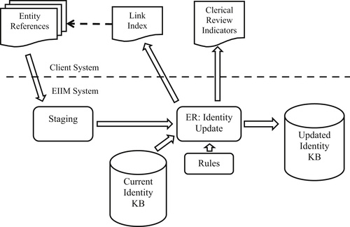
Figure 5.1 shows the data flow in the automated update process. It closely resembles the capture process shown in Figure 3.1. The only essential difference is the current identity knowledge base (IKB) is an input into the ER process along with the new entity references.
New entity references are first staged for data cleansing and standardization. Prior to the new references entering the ER process, the EIS from the current IKB are loaded into the system. Both the new references and previous EIS participate in the ER matching process to build the new IKB.
The update process is driven by resolving the new input references. As each input reference is processed, one of three things will happen.
1. The input reference fails to match any of the existing EIS up to that point in the process. This includes the initial set of EIS from the current IKB along with any newly formed EIS from processing previous input references. If no matches are found for the input reference, the system creates a new EIS comprising only that reference.
2. The input reference matches exactly one of the EIS in the system. In this case, the reference is integrated into the EIS it matches.
3. The input reference matches two or more EIS in the system. By the transitive closure principle of reference equivalence (more on this in Chapter 8), the reference and all of the EIS the reference matches are merged into a single EIS. References causing EIS to merge are sometimes called glue records.
From the perspective of the output IKB, each EIS in the updated IKB is either
• An EIS already in the current IKB and unaffected by the update process, i.e. no new references matched the EIS
• A new EIS created entirely from one or more new input references
• An EIS already in the current IKB, but was updated by matching one or more of the new input references. In addition to being updated by new input references, the EIS may have absorbed one or more of the original EIS if a new input reference caused them to merge, i.e. acted as a glue record.
At the end of every update, the system should generate statistics for all of these occurrences.
Clerical Review Indicators
A component common to both the capture and automated update process are clerical review indicators as shown in both Figures 3.1 and 5.1. Clerical review indicators are simply warnings produced by the ER process that a linking error may have occurred. These indicators are produced by code detecting particular events or conditions correlated with linking errors.
The concept of review indicators has been a part of entity resolution and record linking since its beginning with the Fellegi-Sunter Theory of Record Linking (Fellegi & Sunter, 1969). An essential element of their proof was that, in order for a match rule to meet a given constraint on the maximum allowable false positive and false negative rates, some minimal number of reference pairs would have to be manually reviewed by a data expert who could correctly classify them as being equivalent or not equivalent. In the case of the Fellegi-Sunter model, the review indication occurs when a pair of references satisfied a particular agreement pattern. For example, in matching student enrollment records, the pattern of disagreement on first name, but agreement of last name, date-of-birth, and house number might fall into this review category. The pattern strongly suggests the records may be referencing the same student but also the possibility the records satisfying this match pattern are twin siblings. Sometimes these are called soft rules or weak rules. Instead of signaling a match, the firing of these rules signals the need for clerical review.
Similar to the conundrum posed by ER assessment one might ask, if the system knows that an error condition leading to a linking error has occurred, why not program the system to avoid the condition and avoid the error? Again the answer lies with probabilities. A review indication is produced by the system when the condition or event is associated with a higher probability a linking error has occurred, not a certainty. Review indicators are not perfect. A review indication may be a false alarm, and conversely, linking errors may occur that do not produce a review indicator.
Review indicators also play a critical role in continuous improvement. If a reviewer determines the system made an error, then correcting these errors will clearly improve the accuracy of the IKB. But more so, a careful root cause analysis of errors over time can inform refinements and improvements to the matching logic preventing these errors from happening. Clerical review indicators together with ER outcome analysis and root cause analysis form a continuous improvement cycle for ER and MDM.
Again, it is hard to overemphasize the need for these components to be in place in order to have a highly effective and efficient MDM system. While many users rely primarily on initial quality assurance validation processes applied to the reference sources, the ones most often neglected are
• Systematic evaluation of ER accuracy using truth sets, benchmarking, and problem sets.
• Review indicator logic signaling possible errors in EIS caused by matching. This is essentially a second level of quality assurance examining the coherence of references vis-à-vis other references for the same entity (same EIS), as opposed to the validation of each source examining the coherence of references vis-à-vis other references from the same source.
• Actual human review of each exception signaled by a review indicator resulting in either a correction or confirmation action.
Even the analysis of cases where the reviewer finds the indicator was wrong and the ER decision was actually correct (a false alarm) can contribute to performance improvements by leading to refinements in the review indicator logic. In addition, if a system allows reviewer decisions to be captured in the metadata of the IKB, the system can suppress review indications on EIS that have previously been reviewed and found correct. These confirmation assertions can significantly decrease the time and effort required for clerical review. The transactions causing indicator logic to be suppressed on combinations of EIS already reviewed as correct are called true assertions or confirmation assertions. In contrast, transactions used to correct errors are called correction assertions.
Pair-Level Review Indicators
Review indicators are typically designed to work at one of two levels: at the reference matching pair level and the cluster level. The previous example of a Fellegi-Sunter agreement pattern falls into the category of pair-level indication. In other words, the review signal is associated with a pair of references satisfying a certain match condition, in this case, that the two references follow a specific agreement pattern.
Scoring rules discussed in Chapter 3 provide natural pair-level review indicator logic. By setting a second threshold score just below the match score threshold, the system can give an indication on every pair of references scoring below the match threshold and above the second threshold, called a review threshold. These represent pairs with scores close to being a match but just falling short, i.e. near matches.
Even though a Boolean rule set does not generate a score, some systems allow for some sub-rules (AND clauses) to be designated as a soft rule or weak rule. A weak rule allows for more fuzziness or looseness in the match. The weak rule can be treated either as a match or a no-match, but in either case, the pairs of references satisfying a weak rule are called out for clerical review.
Cluster-level Review Indicators
Even for experts in a given data domain, decisions on clerical reviews can sometimes be difficult. In making these decisions it often helps to have the complete context. Cluster-level review indicators can provide this much-needed context by showing the contents of the EIS associated with a pair of references. Another advantage of cluster-level indicators is they can be applied at two different times: at run-time while the EIS is in main memory and matching is taking place, or they can be applied to the EIS in off-line storage after the ER process is complete.
As an example, Pullen, Wang, Talburt, and Wu (2013a) developed review indicator logic for ER systems using Shannon’s entropy formulation. The entropy calculation is done by looking at the frequency of distinct values of identity attributes of the references within a cluster. For example, suppose a cluster representing a student has 10 references and one of the identity attributes is the student’s first name. If 7 of the references have the first name value of “JAMES” and 3 of the references have the first name value of “JIM” then the probability of the first name “JAMES” would be 0.7 and the probability of “JIM” would be 0.3. From this the entropy of the first name values would be given by

A similar calculation for each identity attribute contributes to a total entropy score for the entire cluster. Their work shows that, for certain types of data, a high entropy value for a cluster is a high-precision indicator of a potential false positive error, i.e. more than one entity is represented in the cluster.
Conversely, they have also shown that low entropy can be a good indicator of false negative EIS. To be used as a false negative indicator, closely related EIS must first be brought together by a loose match key. For an example using student data, the false negative key might be a combination of last name and date-of-birth. If two EIS that have the same last name and data of birth are brought together, and if the entropy of the EIS created by combining the references from both EIS is low, then this may indicate the two EIS are false negatives of each other. If two EIS are found to be false negatives, i.e. both reference the same entity, then by transitive closure of equivalence, they should be combined into one EIS.
The Manual Update Process
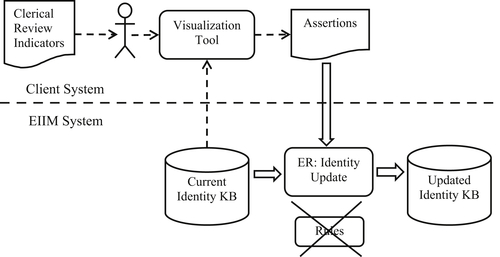
The manual update process is driven by the clerical review indicators. As shown in Figure 5.2, the manual update process begins with a data expert and a set of clerical review indications produced by a capture process or by an automated update process. For a system of any size, the reviewer will need two things. The first is a tool to assist in reviewing the EIS in order to make a review decision, and the second is a mechanism for making adjustments to the IKB based on the decision.
Adjustments made to the IKB by human (knowledge-based) decision are called assertions. If the decision is an error was made, then the action is to correct the EIS in error. If the decision is no error was made, then the action is to confirm the EIS are correct. The assertion process will be discussed first. Once assertions are understood, the functions of the visualization tool will be clearer.
Asserted Resolution
Asserted resolution, sometimes called informed linking or knowledge-based linking, is simply the reconfiguration of the EIS in the IKB based on expert knowledge. Assertions are effected by creating assertion transactions applied to the IKB through the EIIM system. Because asserted resolution is a manual process, the number of assertions applied to the IKB will always be small when compared to the large volume of updates applied through the automated update process. However, assertions are important to reduce the accumulations of false positive and false negative errors, which build up over time in an unreviewed EIIM system. Assertion complements the automated ER process and provides a mechanism for continuous improvement of the EIIM system.
Direct manipulation of the IKB through an editing tool or other ad hoc processes is never a good idea and should be prohibited by MDM governance policy. All update transactions to the IKB including assertion transaction actions should always be mediated through thoroughly tested application software logging transaction events to facilitate process auditability and to maintain IKB integrity.
Correction Assertions
Assertions generally fall into three categories – correction assertions, confirmation assertions, and convenience assertions. Correction assertions are designed to alter EIS in a way that corrects malformation caused by the false positive and false negative errors inevitably occurring in the automated ER process. Confirmation assertions do not alter EIS other than to insert metadata flagging the EIS as being correct. The presence of the confirmation metadata is detected by the review indicator logic to prevent it from calling out for review EIS already confirmed as correct. In addition, the metadata inserted into EIS when correcting a false positive (structure-split-assertion) or confirming a true negative prevents the rules in the automated ER process from merging (or re-merging) EIS that should remain separated.
Structure-to-Structure Assertion
A structure-to-structure assertion is used to correct a false negative error in which two EIS are found to be equivalent, i.e. reference the same entity. Although some false negatives are self-correcting when new references connect the EIS during the identity update process, this is not always the case, and manual intervention may be required. Figure 5.3 shows the schematic of a structure-to-structure assertion.
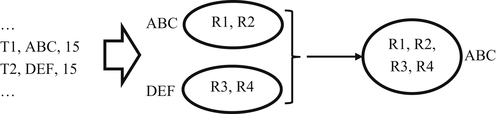
In Figure 5.3, ABC and DEF are forced to merge into a single cluster. To minimize entity identifier changes, the identifier for one EIS is retained, in this case ABC. Only entity identifier DEF will have to be retired. Although Figure 5.3 only shows two EIS being merged, some systems support merging several equivalent EIS in the same assertion.
However, the retirement of DEF from the IKB will orphan any source records residing in the IKB client systems referencing DEF. These records should now reference ABC. The mechanism making this adjustment (synchronization) will depend upon the MDM architecture of the system as discussed previously. For example in a registry architecture, the client systems will have to push their records to the IKB in order to refresh its identifiers, whereas in a reconciliation engine, the IKB will notify client systems with references to DEF that it should be replaced by ABC and the IKB will notify client systems.
A structure-to-structure assertion is effected by a set of assertion transactions shown on the left side of Figure 5.3. In systems that support asserting multiple EIS, if N is the number of EIS to be merged, then N transactions are required, one for each EIS. The structure-to-structure assertion transaction has three fields – a transaction identifier, an entity identifier, and a group identifier.
In Figure 5.3 two EIS are being merged by two structure-to-structure assertion transactions. The transaction identifiers are T1 and T2. Transaction T1 references entity identifier ABC, and transaction T2 references entity identifier DEF. Both transactions have a group identifier value of 15. All EIS sharing the same group identifier value will merge, in this case ABC and DEF. If a third EIS were to be merged in this assertion, there would only need to be a third transaction with the entity identifier of the third EIS and with the same group identifier value of 15.
Structure-Split Assertion
The structure-split assertion is designed to correct false positive errors, i.e. EIS containing references to more than one entity. Unlike false negative errors, false positive errors are never self-correcting through the automated update process. ER processes are driven by matching engines only making decisions to merge EIS, never to split them. Once a false positive EIS is created, it will remain in the system until there is a manual intervention to correct it.
A schematic for the structure-split assertion is shown in Figure 5.4. In this example the EIS ABC contains five references R1, R2, R3, R4, and R5. A clerical review shows references R1 and R2 reference one entity, references R3 and R4 reference a second entity, and reference R5 references yet a third entity. Correcting this problem requires a set of structure-split assertion transactions. Again, to minimize the amount of effort needed to synchronize the client systems, the MDM system will not allow all of the references to be split away from the original EIS. In other words, the system requires that the original EIS must survive the structure-split assertion operation, so the original entity identifier ABC is retained in the system. The structure-split assertion transactions only need to call out the references needing to be moved out of EIS.
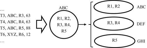
The transactions needed to effect a structure-split assertion are similar to those for structure-to-structure assertion, but they require one additional field. Each structure-split assertion transaction has four fields – a transaction identifier, an entity identifier, a reference identifier, and a group identifier. In Figure 5.4 there are three transactions with identifiers T3, T4, and T5. All of the transactions have entity identifier ABC; however, transaction T3 has the identifier for reference R3, transaction T4 for reference R4, and T5 for reference R5.
In a set of structure-split assertion transactions are two levels of grouping. The first level is by EIS and the second level is by split group using a group identifier. In Figure 5.4, the group of transactions applying to ABC is shown with group identifiers 63 and 88. Within the ABC group are two subgroups – subgroup 63 and subgroup 88. Subgroup 63 indicates references R3 and R4 should move together into a new EIS after being removed from ABC. For R3 and R4 the new EIS identifier is DEF. Subgroup 88 indicates that reference R5 should be in a new EIS, but different EIS than the new EIS created for R3 and R4. For R5 the new identifier is GHI.
The synchronization of identifiers in a client system for structure-split assertions is more difficult than for the structure-to-structure previously discussed. The problem now is clients’ systems may contain many source records referencing identifier ABC, but after the assertion, some of these perhaps should reference the new identifier GHI. Even if the system has kept track of which source records were appended with identifier ABC, it is not obvious which of these should be changed to GHI without having to rematch the records against the identity information. This is another reason why ER systems are usually tuned to prefer false negative errors over false positive errors. Not only do the corrections to false negative errors stay corrected without special logic, the identifier retirement is simpler to manage.
Reference-Transfer Assertion
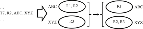
The reference-transfer assertion is designed to correct both a false positive and false negative in one process. Figure 5.4 shows a situation in which the reference R2 has been clustered in ABC with R1, but should have been clustered with R3 in XYZ. In this case, R2 is a false positive with respect to R1 and a false negative with respect to R3. The solution is to move the reference R2 from ABC to XYZ.
No new EIS are created in the reference-transfer assertion process. One reference-transfer assertion transaction exists for each reference needing to be moved. Each reference-transfer assertion transaction has four fields – a transaction identifier, a reference identifier, a source entity identifier, and a target entity identifier. In the example of Figure 5.5, transaction T7 indicates a move of reference R2 from ABC to XYZ as shown in the diagram.
Confirmation Assertions
Confirmation assertions are designed to label EIS as having been reviewed and confirmed as correct in order to prevent their continued review. The algorithms producing clerical review exceptions are not perfect. Some EIS called out for clerical review as potential false positives often turn out to be true positives, i.e. correctly clustered. Similarly, some groups of EIS called out for clerical review as false negatives are in fact true negatives. Without confirmation assertions, these EIS can be repeatedly called out for review by the clerical review indicator logic even though they have previously been manually reviewed and found to be correct.
However, it is important to note EIS reviewed as correct should only be excluded from subsequent reviews as long as they maintain the state they had at the time of the review. Any changes to the EIS could change their status from correct to incorrect. The implementation of confirmation assertions also requires new functionality in the ER update logic that will remove confirmation labels from the EIS metadata whenever the ER process modifies the EIS.
True Positive Assertion
The true positive confirmation assertion pertains to a single EIS. If an EIS is called out for clerical review, and if the reviewer finds all references in the EIS are for same entity, the EIS is a true positive and should be asserted as such. The true positive assertion of an EIS will add a metadata label showing the EIS is true positive.
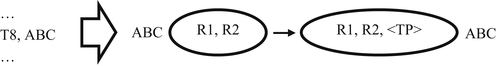
The case shown in Figure 5.6 is where the EIS with entity identifier ABC was called out for clerical review as a false positive, but after inspection it was found to be correct. The true positive assertion transaction requires only two fields – a transaction identifier and the entity identifier of the true positive EIS. The action of the true positive assertion is to add a metadata tag (shown as <TP> in Figure 5.6) to the EIS. True positive assertion transaction T8 asserts ABC as a true positive EIS. The true positive tag inserted into ABC will prevent the clerical review indicator logic from calling out ABC for review as long as the tag is present.
However, if a later update process results in new references being added to ABC, then the true positive tag will be removed, and ABC may again be called out for clerical review in later processing. The metadata added to the true positive EIS may also include other information for auditing and traceability such as an identifier for the person making the review decision, the date of review, and other relevant information. These additional metadata are important for good master data governance.
True Negative Assertion
The true negative assertion confirms two or more EIS were called out for review as potential false negatives have been confirmed as correct by an expert reviewer. Just as with the true positive assertion, the true negative assertion inserts metadata tags into the reviewed EIS. In the case of true negative, additional metadata is required because a true negative state always exists between two (or more) EIS. Just labeling an EIS as a true negative does not make sense by itself. A true negative assertion of an EIS must be expressed in relation to another EIS. In addition to a true negative label, a true negative assertion must also insert the identifier of the EIS to which it is a true negative. These metadata must be inserted into all of the EIS the review process determines to be true negatives of each other.
The example in Figure 5.7 is for two EIS with identifiers ABC and DEF. The true negative assertion transactions require three fields – a transaction identifier, an entity identifier of one of the true negative EIS, and a grouping identifier. The grouping identifier is simply a provided value identifying the EIS comprising the true negative group. The value of the grouping identifier is not as important while it is the same in all transactions relating to the same true negative group and different from the identifier for any other true negative group. In this example, the group identifier is 76 for transactions T9 and T10. Because transaction T11 has a different group identifier, it relates to some other true negative group not shown.
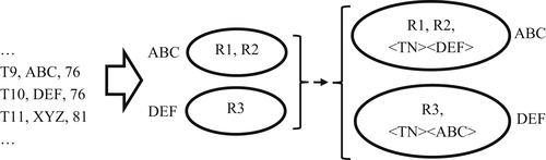
As shown in Figure 5.7, the true negative assertion of the EIS with identifiers ABC and DEF creates metadata cross-referencing these EIS. The EIS with identifier ABC references the EIS with identifier DEF as a true negative, and conversely, the EIS with identifier DEF references the EIS with identifier ABC as a true negative. These tags will prevent the clerical review logic from calling out the EIS identified as ABC and DEF as false negatives in future processes as long as they maintain the original state. Just as with the true positive assertion, the metadata tags suppressing subsequent true negative review must be removed if and when a later update process adds new references to any one of the EIS in a true negative group.
Reference-to-Reference Assertion
Two special types of confirmation assertions are used to move external references into correctly configured EIS. They belong to the category of convenience assertions. Convenience assertions allow the user to directly create and manipulate EIS without using matching rules.
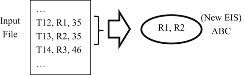
The first convenience assertion is a reference-to-reference assertion used to create a new EIS containing a specific set of source references. The reference-to-reference assertion bypasses the matching rules and in some ways represents a special type of identity capture configuration. Reference-to-reference assertions are often used to migrate intact clusters of references from a legacy MDM system into a new MDM system.
Reference-to-reference assertion transactions require three fields – a transaction identifier, a reference, and a group identifier. As with the true negative assertion, the group identifier serves to show which references are to create the same EIS. In the case of migration from a legacy system, these group identifiers will simply be the entity identifier assigned to the references by the legacy system.
In Figure 5.8, the reference-to-reference assertion transactions T12 and T13 are grouped by identifier 35 indicating references R1 and R2 are to form a new cluster. Depending upon the system, the identifier ABC of the new EIS can be a value automatically generated by the system, or it can be a value specified by the user, and again in the case of legacy migration, could be the group identifier. In the case where identifiers are provided, the MDM system should prevent the user from inadvertently creating duplicate identifiers.
Reference-to-Structure Assertion
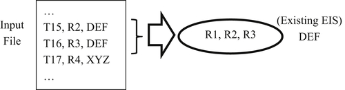
The second type of convenience confirmation assertion is a reference-to-structure assertion used to add one or more references to an existing EIS. As with a reference-to-reference assertion, a reference-to-structure assertion bypasses the matching rules.
As shown in Figure 5.9, the reference-to-structure assertion transactions require three fields – a transaction identifier, a reference, and an EIS identifier. Grouping is unnecessary for reference-to-structure assertion transactions because each transaction names the specific EIS to which the transaction should be added.
In the example of Figure 5.9, reference-to-structure assertion transactions T15 and T16 add references R2 and R3, respectively, to the EIS labeled DEF which is already in existence and contains reference R1.
EIS Visualization Tools
Visualization can be an effective tool for assessing and managing information (Abu-Halimeh, Pullen, & Tudoreanu, 2013; Gibson & Talburt, 2010). This is especially true for Big Data. Large MDM systems can have millions of entities and source references under management. For systems of this scale, clerical review becomes difficult without tools that allow reviewers to quickly access and understand the contents of EIS indicated for review. Conducting reviews using printouts or on-screen listings can be tedious and error prone. Visualization tools with advanced functionality can considerably ease the review burden and increase reviewer productivity and accuracy (Chen et al., 2013b). Some of the helpful features provided by a good visualization tool allow the reviewer to
• Quickly locate and view EIS called out by clerical review indicators
• Allow multiple reviewers simultaneous access
• Keep track of indicator status in terms of “needing review” or “already reviewed”
• Support undirected, keyword searches over the entire IKB in addition to reviews directed by clerical review indicators
• Automatically generate properly formatted correction and confirmation assertions reflecting reviewer decisions
To illustrate these features, the following section will use, as an example, a browser-based IKB visualization tool called Identity Visualization System (IVS) developed by, and shown here with the permission of, Black Oak Analytics, Inc. All of the information shown in the screen shots were created using synthetic data and do not represent actual persons.
First note that IVS, like most visualization tools, does not directly modify the IKB. As depicted in Figure 5.2, the information from the IKB is extracted to the database in the IVS tool allowing IVS to make queries in real time. During the extraction process, all of the tokens in the EIS are indexed to enable real-time keyword searches of the EIS. In addition, the entropy calculations are made during the extraction by user-defined parameters in the extraction script.
Again as shown in Figure 5.2, the output of IVS is a file of assertion transactions. The decisions reviewers make using IVS are not actually reflected in adjustments to the IKB until these transactions are run against the IKB through an ER assertion process. Although the decoupling of the visualization tool from the IKB by this extraction process gives the visualization tool higher performance, it can also lead to synchronization problems if not properly governed.
The primary issue is that reviewers are working on a copy of the IKB, not the IKB itself. If automated updates are applied to the real IKB before the assertion transactions from the clerical reviews have been applied, some assertion transactions made by reviewers may be rendered invalid because of structural changes made to the IKB by the automated update. Contention between updates is always a potential risk with redundant data. In this case, the copy of the IKB manipulated by the visualization tool is redundant to the actual IKB. Redundancy always introduces the possibility for loss of synchronization between copies of the same data.
Assertion Management
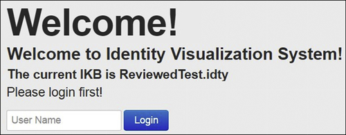
The initial login screen for the system is shown in Figure 5.10. By requiring reviewers to login, the system can keep track of which indicated EIS have been reviewed and by which reviewers. The login identifier is also carried forward into all of the assertion transactions generated by the reviewer. When the assertion transactions are applied, the reviewer identifier is inserted into the metadata of the asserted EIS in order to enable the auditability of assertion transactions.
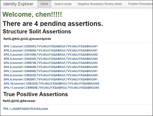
When the reviewer logs into IVS, the system starts on the reviewer’s home page. The home page shows the status of work for the reviewer since the last review session. The home page depicted in Figure 5.11 shows that the reviewer “chen” has made four assertions in a previous review session. These assertions are labeled as “pending” because even though the assertion decisions have been made, and the assertion transactions have been generated, the assertion transactions have not yet been applied to the IKB.
An interesting feature of the IVS is the user interface resembling an online shopping model. As reviewers make assertion decisions, the decisions are saved in an “assertion cart” similar to an online shopping cart. When a reviewer makes an assertion decision for an indicator, the asserted indicator is put into the cart. At the same time, the indicated EIS is removed from the reviewer’s queue of indicated EIS to review.
At any point in the session the reviewer can view the assertions in the cart, and if he or she so chooses, can “commit” the assertions in the cart. The commit step causes the IVS to generate assertion transactions for the decision in the cart, analogous to “purchasing” the items in a shopping cart. Once the decisions are committed to transactions, the cart is emptied and the assertion transactions become pending assertions as shown in Figure 5.11.
Because the screen shot has been cropped to fit the page, only the assertion transactions generated for two of the four pending assertions can been seen in Figure 5.11. Visible here are 11 structure-split transactions pending for application to the EIS with identifier 7VVJ4UJYXQABKIUI. As discussed in the previous section, each split-assertion transaction has four values – a transaction identifier, a reference identifier, an EIS identifier, and a grouping identifier. For example, the first transaction shown has a transaction identifier of SPA.1, a reference identifier of source1.C929503, the EIS identifier 7VVJ4UJYXQABKIUI, and a grouping identifier of 7VVJ4UJYXQABKIUI#1.
The grouping identifiers have been generated by appending an integer value to the EIS identifier to create a set of unique identifiers for the groups specified by the reviewer. There are three distinct grouping identifiers in the eleven transactions. However, when these 11 transactions are applied to the IKB they will only create two new EIS. The system will automatically select the largest subgroup to retain the base EIS with identifier 7VVJ4UJYXQABKIUI. The two small groups will create two new EIS with new identifiers generated by the system. This process will assure the fewest possible identifiers are changed, and the fewest possible references are given new identifiers.
The top of Figure 5.11 includes tabs showing the three basic operating modes of IVS – Search Mode, Negative Resolution Review Mode, and Positive Resolution Review Mode. The Search Mode allows the reviewer to perform undirected keyword searches of the IKB. Negative Resolution Review Mode shows the reviewer EIS indicated as possible false negatives, and the Positive Resolution Review Mode shows the reviewer EIS indicated as possible false positives.
Search Mode
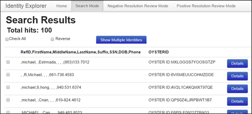
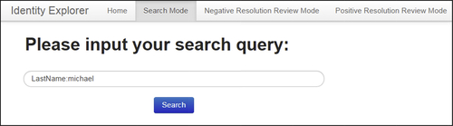
Figure 5.12 shows the search mode input screen. The reviewer can type any sequence of keywords here to perform an undirected search of the entire IKB. In this case, the search is to be performed on the single token value “michael”.
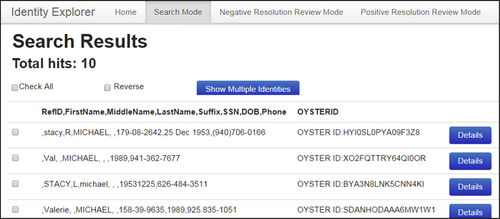
As a result of the search, 100 EIS were found that contained references with the value “michael” in any one of the attribute values. The partial search results are shown in Figure 5.13. The IVS tool will search on multiple keywords both qualified and unqualified. The first reference returned has “michael” in the first name field and the second reference has the value “michael” in the last name field.

In a qualified search the token is prefixed by an attribute name. Figure 5.14 shows a qualified keyword search for references where the token value “michael” is found in the last name field “LastName:michael” and will only search for EIS in the first name field containing the value of “michael”.
The results of the directed search are shown in Figure 5.15.
Negative Resolution Review Mode
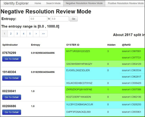
Upon entry into the negative resolution review mode, IVS will show the reviewer the EIS groups indicated as possible false negative groups. Because IVS uses the entropy-based clerical review described in the previous section, the groups brought together by the split key are arranged in order from lowest to highest entropy. Figure 5.16 shows the four groups with the lowest entropy when brought together by the split key. In this case the split key is the first 8 digits of the social security number.
To enhance readability for the reviewer, different EIS within a group and different groups have different colored backgrounds. The reviewer can also select different bands of entropy to review. In this example, the band of entropy values between 0.0 and 5.0 entropy is displaying 2,817 EIS groups for review.
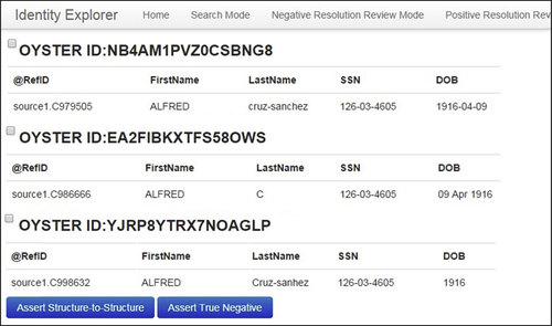
At the detail level, the reviewer can see the attribute-level information in each reference. Figure 5.17 shows the detail level of three EIS brought together by a split key. In this example are three EIS brought together by the split key, and each EIS comprises a single reference.
The check boxes at the left of each EIS allow the reviewer to select which EIS should be designated as either true negatives or false negatives that should be merged. After the EIS are selected by their check boxes, the decision is effected by clicking the appropriate button at the bottom of the screen.
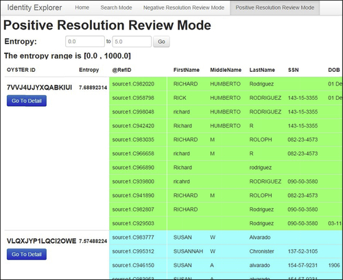
Positive Resolution Review Mode
The positive resolution review mode function is similar to the negative resolution review mode. Figure 5.18 shows the indicator level list of EIS for positive review mode. In positive review mode the EIS are listed in descending order of entropy scores, since high-entropy EIS are more likely to be false positive.
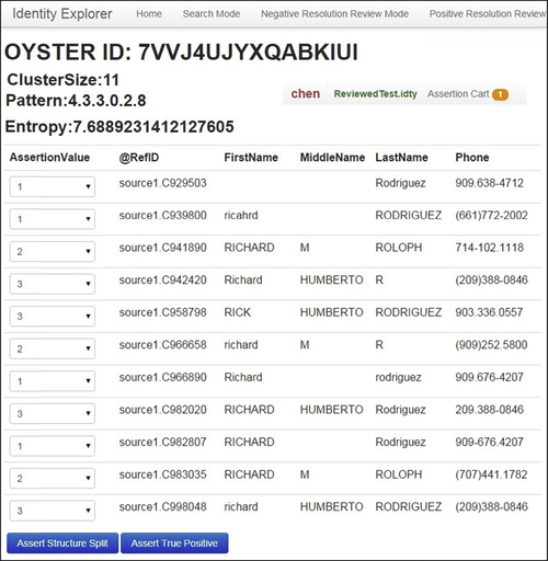
By clicking the “Go To Detail” button, the reviewer is taken to the detail level screen as shown in Figure 5.19. The EIS shown in Figure 5.19 is the same EIS with identifier value 7VVJ4UJYXQABKIUI shown in Figure 5.18.
Note that in Figure 5.19, the reviewer has already determined the EIS is a false positive and had already selected how the references should be correctly grouped. The groupings are created by selecting an integer value for the drop-down boxes at the left of each reference. After the grouping codes are selected, the reviewer will click the “Assert Structure Split” button at the bottom of the page. The right end of the main menu bar has been moved into view to show the count of assertions currently in the Assertion Cart. By clicking on the Assertion Cart, the reviewer can see all of the assertions that he or she has reviewed since the last commit.
Managing Entity Identifiers
The entity identifiers in an MDM system are called “persistent” identifiers rather than “permanent” identifiers for good reason. Because MDM systems are driven by ER processes, and ER processes make mistakes, some entity identifiers are going to change when these mistakes are corrected.
Take, as an example, the false negative error in Figure 5.3. Before the error was discovered, the EIS identified as ABC and DEF were believed to represent different entities. The references R1 and R2 were assumed to reference entity ABC and references R3 and R4 referenced entity DEF. After the correction, only the identifier ABC survived. The result is that reference R3 and R4 changed identifiers.
Similarly, before the false positive error shown in Figure 5.4 was discovered, references R1, R2, R3, R4, and R5 were all believed to reference the entity identified as ABC. After the correction two new entity identifiers are in the system, the identifier DEF for the entity defined by references R3 and R4, and identifier GHI for the entity defined by reference R5. The net result is changed identifiers for reference R3, R4, and R5.
The Problem of Association Information Latency
One factor driving the false negative problem, especially with customer entities, is association information often lagging behind existence information. For example, when a customer moves from one address to another, whether postal or electronic address, a transaction seen at a new address without reference to an old address often appears to be a new customer. When this happens, the system creates a new EIS and new identifier. It is only later that the association information, such as a postal change-of-address transaction, will appear connecting the customer at his or her new address and old address. In applications where this happens frequently, the result can be a churning effect where new identifiers are created and then quickly retired.
Models for Identifier Change Management
Regardless of the cause for identifier changes, these changes must be dealt with. Two basic models include the pull or user-directed model and the push or system-directed model.
The Pull Model
In the pull model all of the source information from client systems is pulled back to the MDM system where it is relinked, i.e. the current identifiers are appended to the client source records. In this model, it is the client system’s responsibility to detect when an identifier has been changed and to take the appropriate actions.
In this division of responsibility, the central MDM system is primarily an identity management system focused on maintaining the identity integrity of its IKB. The central system does not maintain a log of which identifiers have been given to which client systems. The client systems must periodically relink in order to be assured of having the most current identifiers. The pull model is common when there are many client systems using the identifiers, especially when some of the clients are in organizations or information systems separate from the MDM system.
The advantage of the pull model is that from an MDM system viewpoint, it is simpler to manage. By placing the burden on client systems to harmonize identifiers, the MDM system itself is less complex. Of course, the obvious disadvantage of the pull model is the potential loss of synchronization of identifiers across client systems. The extent to which this can happen will depend upon the nature of the application, the volatility of the data, and the frequency of the synchronization process. If updates to the IKB are done on a regular schedule, then relinking can be timed to coincide with the updates in order to minimize the synchronization problem.
The Push Model
In the push model of identifier change management, it is the central system’s responsibility to publish changes in identifiers to the client systems. Several different versions of the push model vary in sophistication. In the simpler version, all changes are published to all clients, and it is still the client’s responsibility to determine which changes are pertinent to its references and to appropriately adjust the identifiers.
In more sophisticated versions of the push model, the central system keeps track of which identifiers have been given to which clients. In this way the central system can notify (or not notify) each client about changes to identifiers specific to a client. In the most sophisticated approach, the central system and the client systems are integrated to the extent that the central hub actually effects the identifier changes in the client system.
Concluding Remarks
To obtain the highest level of identity integrity in an MDM system it is necessary to undertake manual, human-in-the-loop correction and confirmation assertions to complement the automated update process. Automated update processes will always produce some level of false positive and false negative errors. Left uncorrected, these errors will accumulate and, over time, will degrade the identity integrity of the system.
At the same time, successful manual updates require support from two other systems- clerical review indicators and EIS search and visualization tools. The review indicators help the MDM data steward focus their attention on the EIS most likely to have these errors. The visualization tool provides them with the capability to rapidly look up these EIS, view them in context, and record their assertion decisions. A robust visualization tool can also assist the data stewards in generating valid assertion transactions, and even help manage and coordinate the overall assertion workflow. This can be especially important when several operators are working concurrently on the same identity knowledge base.
..................Content has been hidden....................
You can't read the all page of ebook, please click here login for view all page.