
6
Flat Wings in Inviscid Supersonic Flow
Although the wing and the fuselage are the most influential components contributing to aerodynamic drag, in supersonic airplane all main components for optimum efficiency of the complete vehicle must be integrated. For instance: the best airfoil section is not necessarily the section to be used with the optimum planform of the isolated wing, whereas the best planform alone is not necessarily the best to be used for the wing–body combination. In the conceptual design stage of a supersonic cruise vehicle (SCV) this problem may be solved by first conceiving the best wing shape and the best fuselage layout. Significant aerodynamic interaction effects are then identified by means of the area ruling method applied to the complete configuration. However, the design of an optimized SCV wing–body configuration is a complex exercise that will be the subject of Chapters 7 and 8.
The present chapter aims at comparing basic aerodynamic properties of three‐dimensional wings based on results generated with linearized theory. The requirement that the disturbances in the flow are infinitesimally small requires that thin and planar wings – also known as flat‐plate wings – form the initial subject of the present study. A flat‐plate wing is neither cambered nor warped or twisted, a generic shape that has been studied at length because its flow type is illustrative for lifting wings at supersonic speed in general. Pressure drag due to thickness is not taken into account in the present chapter, as opposed to the more comprehensive analysis in Chapter 7 that aims at predicting the pressure drag due to thickness of more realistic wings. Nevertheless, experimental studies have shown that the aerodynamic performance of flat‐plate wings with rounded (or “blunt”) leading edges can be estimated adequately at small incidences when the flow remains attached over the entire wing surface. Their predicted theoretical performance can be useful for the initial design stage whereas a reliable analysis of aerodynamic performance in more advanced design stages requires the use of an accurate definition of the aircraft geometry and more complex methods to predict the aerodynamic properties by means of non‐linear theories and computational fluid dynamics (CFD) methods.
6.1 Classification of Edge Flows
The lift, drag, and pitching moment of a wing are primarily affected by the Mach number component normal to the leading edge. The following definitions are used in the general case of an arbitrary planform with straight as well as cranked or curved edges:
- A supersonic leading edge is a (portion of the) leading edge where the component of the oncoming flow normal to the wing edge is supersonic.
- A subsonic leading edge is a (portion of the) leading edge where the component of the oncoming flow normal to the wing edge is subsonic.
Similar definitions apply to supersonic and subsonic trailing edges and side edges. A wing may have supersonic as well as subsonic edges. Wings with only supersonic leading and trailing edges are commonly referred to as having a “simple plan‐form” because their aerodynamic analysis is considerably simpler than that of a wing with subsonic edges.
An essential consequence of the present classification is that in the case of a sharp supersonic leading edge there is no interaction between the lower and the upper surface flow. However, if the nose of a subsonic leading edge is blunt, the pressure difference between the lower and upper surfaces may lead to the phenomenon of local subsonic flow and a stagnation point just below the leading edge, causing a high‐speed upward airflow and a pronounced suction peak in front of the nose. The overall result of the distributed suction force is known as leading‐edge suction, which can bring about a valuable reduction in the pressure drag. This essential subject is treated in Chapter 9. Another consequence for the solution of the three‐dimensional potential flow equations is that subsonic trailing edge flow must comply with the Kutta condition, for which the pressure coefficient at the trailing edge at the upper and lower wing surfaces are equal and, hence, the local lift at a subsonic trailing edge is zero.
6.2 Linear Theory for Three‐dimensional Inviscid Flow
As noted in Chapter 5, the pressure distribution derived from linearized theory results in a wave drag component, even if shock waves are absent and the flow is assumed to be isentropic. Different from the small‐perturbation theory for 2D flow around wing sections, which is based on Equation (5.3), Laplace's equation governing the perturbation velocity potential for three‐dimensional flow is a second‐order linear partial differential equation of the hyperbolic type,
Solutions of the linearized three‐dimensional theory describe essential aerodynamic properties such as the lift curve slope and the drag due to lift of flat wings with ![]() . However, the linearized theory applies exclusively to isentropic irrotational flow and hence the presence of downwash and a shear layer behind the wing trailing edge must be taken into account by other means.
. However, the linearized theory applies exclusively to isentropic irrotational flow and hence the presence of downwash and a shear layer behind the wing trailing edge must be taken into account by other means.
A classical solution for Equation (6.1) is the conical‐flow method that was first proposed by A. Busemann [9]. A conical flow exists in supersonic flow when properties such as velocity components and pressure are invariant along rays emanating from a point where the flow is perturbed. Solutions generated using the conical‐flow method were used extensively before the advent of digital computers, although they are still useful to serve as a comparison check to computerized methods. Representative examples of conical flows are observed at the tips of a rectangular wing and at the upper surface of a delta wing with supersonic leading edges.
6.2.1 Flow Reversal Theorems
A remarkable and useful approach to drag minimization problems is to employ certain general theorems that relate the lift and pressure drag distributions in forward and reverse flows. A particular flow reversal theorem states that the pressure drag due to the lift of a wing with given lift distribution is equal to the pressure drag when flying with the same incidence in the opposite direction. Such theorems were first put forward in 1947 by Th. Von Kármán and W.D. Hayes, whereas in 1950 M.M. Munk introduced the concept of a combined flow field concluding that the vortex‐induced drag must be the same in forward and reverse flow. Flow reversal theorems have also been used by R.T. Jones to derive criteria for identifying configurations of minimum drag [1].
6.2.2 Constant‐chord Straight Wings
Early applications of linear flow theory were developed during the early 1980s for flat plate wings with constant chord. Geometric parameters of the wing to be studied were its aspect ratio and the angle of sweep. In particular the rectangular wing has been studied by many investigators. The flat rectangular wing depicted in Figure 6.1 is surrounded by supersonic flow normal to its leading and trailing edges. The pressure at any point P on the wing is affected only by disturbances generated at points within the Mach cone emanating upstream from P. Since perturbations occur only at the two tip leading edges, the wing pressure distribution is affected in triangular regions within the Mach cones emanating from the tips.
Figure 6.1(c) depicts the variation of lift produced by the tip Mach cones, a classical example of conical flow defined by

where ![]() and
and ![]() are defined in Figure 6.1(a). Equation (6.2) applies to isolated rectangular wing tips, and the lift per unit area generated by the region inside each tip Mach cone is 50% of the lift per unit area of a two‐dimensional wing. The remainder of the wing between the tip Mach cones is not influenced by any upstream perturbation and hence the pressure distribution in this region can be derived from the two‐dimensional theory exposed in Chapter 5.
are defined in Figure 6.1(a). Equation (6.2) applies to isolated rectangular wing tips, and the lift per unit area generated by the region inside each tip Mach cone is 50% of the lift per unit area of a two‐dimensional wing. The remainder of the wing between the tip Mach cones is not influenced by any upstream perturbation and hence the pressure distribution in this region can be derived from the two‐dimensional theory exposed in Chapter 5.
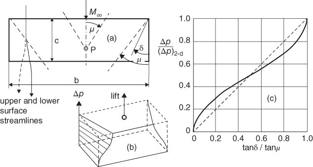
Figure 6.1 Pressure distribution and streamlines for a flat rectangular wing. (a) Conical flow regions and upper and lower surface streamline deflection at the tips. (b) Three‐dimensional pressure distribution. (c) Variation of the pressure difference inside the tip Mach cones.
From Equation (6.2) it can be derived that, relative to a two‐dimensional wing with the same incidence to the flow, the lift and the pressure drag due to lift ![]() of a rectangular wing are reduced by a factor
of a rectangular wing are reduced by a factor ![]() , where the aspect ratio is defined as
, where the aspect ratio is defined as ![]() . Alternatively, the lift gradient and the coefficient of pressure drag due to lift can be written as follows:
. Alternatively, the lift gradient and the coefficient of pressure drag due to lift can be written as follows:
Equation (6.3) suggests that the effect of varying the aspect ratio of a rectangular wing in supersonic flow is less essential compared to subsonic flow. It can also be shown that the center of pressure of a rectangular wing shifts forward from the mid‐chord point in two‐dimensional supersonic flow over a distance
Inspection of this result indicates that the effects of the finite aspect ratio on the aerodynamic properties of a rectangular wing are not negligible for slender wings that have an aspect ratio ![]() typically less than one. However, the following restrictions on the validity of the present theory must be taken into account:
typically less than one. However, the following restrictions on the validity of the present theory must be taken into account:
- Equations (6.2) through (6.4) are valid on the provision that the Mach cones emanated by the tips do not intersect at the wing plane, which appears to be case for
 . If this condition is not satisfied the analysis must be extended to the case that the tip cones are interacting. The pressure distribution in the region of overlap is then determined by adding the pressures inside each tip cone and subtracting their sum from the pressure field as determined by the two‐dimensional linearized theory.
 - Inside the tip Mach cones there is an exchange of pressure between the lower and the upper surfaces leading to an upward flow around the tips. Figure 6.1(a) shows that the streamlines are deflected inwards at the lea‐side surface and outwards at the lower surface. Inside the Mach cones the discontinuity of lateral flows behind the trailing edge causes a shear layer behind the outboard wing. The drag associated with this phenomenon may be treated with a non‐linear theory including viscosity, but its effect is insignificant unless the wing has a very small aspect ratio so that it must be treated as a slender wing. In that case a strong conical vortex will develop at the side edges. Such a wing is unlikely to be a candidate for application for an efficient SCV.
6.2.3 Constant‐chord Swept Wings
Since the lift/drag ratio of a rectangular wing at supersonic speeds appeared to be even worse than that of two‐dimensional wing sections, it was soon realized that application of leading‐edge sweep is required to obtain acceptable high‐speed flight performances. Consequently, swept wings became the subject of many investigations and applications to a generation of transonic military aircraft. The flow around a swept wing with constant chord length exhibits a pressure distribution that is highly dependent on the flight Mach number, as illustrated in Figure 6.2.
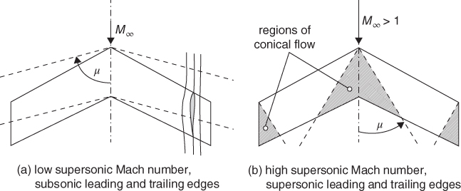
Figure 6.2 The flow around swept wings with constant chord.
- If the wing is sufficiently swept so that the leading and trailing edges are subsonic, the flow around the wing has everywhere a subsonic character. Even if the flight speed is supersonic, a wing with subsonic leading edges in the design (cruising) condition may feature acceptable aerodynamic design properties. For instance, the nose of a wing with subsonic leading edge can be smoothly rounded without generating a drag‐producing bow wave in front of a blunt nose in two‐dimensional flow (Figure 6.1).
- If the flow Mach number is high so that the leading and trailing edges are supersonic, Mach cones not only originate at the tip leading edges but also at the the wing apex. In this situation the center portion is covered by a Mach cone in which the trailing edges exhibit upward oblique shock waves and downward expansion waves. Compared to a rectangular wing with the same span and chord, the three regions with reduced pressure together are larger and their effects on the lift curve slope, wave drag due to lift, and pitching moment are more pronounced.
As the flight speed is increased to higher Mach numbers, the angle of sweep has to be increased in order to keep the leading edge subsonic and it becomes increasingly difficult to keep the flow perturbations small. Experiments have shown that the associated flow separation over the upper wing surface are highly non‐linear, with the effect that the theoretical benefits of sweep‐back are not always attained in practice. Elimination of separated flow in the design condition can be achieved by blending the effects of leading‐ and trailing‐edge sweep‐back angles, thickness distribution, leading‐edge nose radius, and camber and twist variation along the span. However, similar to the rectangular wing, the constant‐chord swept wing with supersonic leading edges has unfavorable aerodynamic properties for application to a supersonic cruise vehicle.
6.3 Slender Wings
Classical supersonic wing theory indicates that, in order to achieve low drag in cruising flight, the leading edge must have an angle of sweep greater than the Mach angle1. A wing is considered as slender if it has a small span compared to its length; in other words, slender wings have a low aspect ratio2. The first generations of (military) supersonic aircraft often used thin rectangular and low aspect ratio straight or swept‐back wings. One aim of their aerodynamic design has been to find shapes that would combine adequate flight performances as well as good flying qualities. This geometry ruled out airfoils with blunt leading edges resulting in poor supersonic performance, whereas wings with sharp leading edges cannot support the classical attached flow required to fly at low speeds, unless variable‐geometry devices such as leading‐edge flaps are applied. These requirements lead to the concept of a configuration with sufficiently swept and aerodynamically sharp leading edges where separation is fixed under all flight conditions. For application at cruise speeds higher than Mach 2 a delta wing is geometrically slender; that is, the aspect ratio should not be greater than approximately one. Moreover, the leading edges are attachment lines at one flight condition.
6.4 Delta Wing
A classical planform applied to supersonic airplanes is the delta wing, which allows application of a slender shape with acceptable aerodynamic properties at high Mach numbers as well as in subsonic flight. The delta wing concept was developed by German engineers during the second World War and has often been used for military applications, in particular because delta wings have excellent aerodynamic properties at transonic and supersonic speeds. The basic triangular delta wing shape depicted in Figure 6.3 has a low aspect ratio (typically ![]() ) with highly swept leading edges, zero trailing‐edge sweep and zero taper ratio3.
) with highly swept leading edges, zero trailing‐edge sweep and zero taper ratio3.
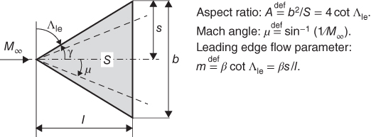
Figure 6.3 Basic delta wing geometry and definitions of flow parameters.
The character of the flow past a flat delta wing is characterized to a large extent by the leading edge flow parameter ![]() , with
, with ![]() denoting the complement of the leading edge sweep angle
denoting the complement of the leading edge sweep angle ![]() as depicted in Figure 6.3. For a sonic leading edge the flow parameter
as depicted in Figure 6.3. For a sonic leading edge the flow parameter ![]() , whereas for a supersonic leading edge
, whereas for a supersonic leading edge ![]() and for a subsonic leading edge
and for a subsonic leading edge ![]() . The relation between the wing area
. The relation between the wing area ![]() , the aspect ratio
, the aspect ratio ![]() , and the leading edge sweep angle
, and the leading edge sweep angle ![]() in Figure 6.3 holds for a pure delta wing and is not exactly valid for modified versions of the basic delta shape, treated in Section 6.6. Since the flow around slender wings in general is primarily determined by the leading edge sweep angle,
in Figure 6.3 holds for a pure delta wing and is not exactly valid for modified versions of the basic delta shape, treated in Section 6.6. Since the flow around slender wings in general is primarily determined by the leading edge sweep angle, ![]() is the preferred definition for the flow parameter. Moreover, it is also valid for arrow wings with straight leading and trailing edges for which the definition
is the preferred definition for the flow parameter. Moreover, it is also valid for arrow wings with straight leading and trailing edges for which the definition ![]() does not apply.
does not apply.

Figure 6.4 Geometry and pressure distribution of a flat delta wing with straight supersonic leading edges.
6.4.1 Supersonic Leading Edge
Figure 6.4 depicts a delta wing at an incidence ![]() to the oncoming flow with speed of such a magnitude that the component of the speed normal to the leading edge
to the oncoming flow with speed of such a magnitude that the component of the speed normal to the leading edge ![]() exceeds the sonic velocity; that is,
exceeds the sonic velocity; that is, ![]() . As explained in Section 6.2, a pressure disturbance generated on a supersonic leading edge only affects the region within the Mach cone emanating from the point where the disturbance is generated. Consequently, point P on the leading edge only experiences the influence of upstream pressure disturbances produced within the Mach cone mirrored forward from it. This cone extends within the zone of silence in front of the leading edge and hence no point on the wing produces a disturbance that influences the flow at any point located at the leading edge.
. As explained in Section 6.2, a pressure disturbance generated on a supersonic leading edge only affects the region within the Mach cone emanating from the point where the disturbance is generated. Consequently, point P on the leading edge only experiences the influence of upstream pressure disturbances produced within the Mach cone mirrored forward from it. This cone extends within the zone of silence in front of the leading edge and hence no point on the wing produces a disturbance that influences the flow at any point located at the leading edge.
A pure delta wing has straight leading edges and the only disturbance affecting its pressure distribution is located at the vertex A, which emanates a disturbed flow field inside the conical Mach wave. The flow in front of this flow field, sketched in the inset figure, is similar to a supersonic two‐dimensional flow, for which the constant pressure difference between the upper and lower surface follows from Ackeret's theory, when applied to ![]() . In this region, the constant lift per unit area proves to be larger than for a two‐dimensional wing with the same Mach number and incidence. Within the Mach cone emanating from A there is a conical‐flow field as defined in Section 6.2.2.
. In this region, the constant lift per unit area proves to be larger than for a two‐dimensional wing with the same Mach number and incidence. Within the Mach cone emanating from A there is a conical‐flow field as defined in Section 6.2.2.
Figure 6.4(b) indicates that in this region the pressure difference has a minimum in the plane of symmetry, and no points on the trailing edge experience the influence of adjacent points. The Kutta condition is not satisfied at the trailing edge and hence the pressure difference and the lift disappear abruptly, indicating the presence of shock waves and expansion regions as sketched. If the pressure distribution for the region within the Mach cone is computed with the conical‐flow method it is concluded that the integrated pressure force on the wing is less than that according to Ackeret's theory.
Instead of computing the flow with the conical‐flow method, the flow reversal theorem can be applied, with the implication that the normal pressure force of the delta wing with supersonic leading edges is equal to the pressure force on the same delta wing in reversed flow. Accordingly, the trailing edge then becomes a straight supersonic leading edge in the reverse flow, producing a constant normal pressure on the upper and lower wing surface and hence the flat delta wing with supersonic leading edges generates the same average lift per unit of area as a two‐dimensional flat plate at the same incidence to the flow approaching from behind,
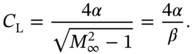
The lift gradient is thus obtained from ![]() , whereas the induced drag is obtained by using Figure 6.3 as follows:
, whereas the induced drag is obtained by using Figure 6.3 as follows:
The induced drag can also be written as ![]() , indicating that accepting a supersonic leading edge brings about a considerable induced drag penalty compared to the ideal minimum induced drag at subsonic speeds.
, indicating that accepting a supersonic leading edge brings about a considerable induced drag penalty compared to the ideal minimum induced drag at subsonic speeds.
6.4.2 Subsonic Leading Edge
When a delta wing is placed in a lower‐supersonic airflow, the Mach angle increases and the Mach waves emanating at the wing vertex rotate towards the leading edge. For the situation in Figure 6.5, the speed is low enough to make the Mach angle ![]() larger than the angle
larger than the angle ![]() and the flow parameter
and the flow parameter ![]() becomes less than one. The velocity component normal to the leading edge is now subsonic and the entire wing is inside the Mach cone emanating from the vertex. In this situation the wing has a subsonic leading edge and a supersonic trailing edge, whereas point P on the leading edge experiences the influence of pressure disturbances emanated by all points within its (mirrored) upstream Mach cone originating from the shaded area of the wing. Although the flow past the leading edge is supersonic, its character is determined by the subsonic component
becomes less than one. The velocity component normal to the leading edge is now subsonic and the entire wing is inside the Mach cone emanating from the vertex. In this situation the wing has a subsonic leading edge and a supersonic trailing edge, whereas point P on the leading edge experiences the influence of pressure disturbances emanated by all points within its (mirrored) upstream Mach cone originating from the shaded area of the wing. Although the flow past the leading edge is supersonic, its character is determined by the subsonic component ![]() and, similar to Figure 6.2(a), the leading edge of a delta wing is surrounded by flow from the stagnation point below the nose, generating a forward suction force the nose which effectively acts as a reduction of the drag4.
and, similar to Figure 6.2(a), the leading edge of a delta wing is surrounded by flow from the stagnation point below the nose, generating a forward suction force the nose which effectively acts as a reduction of the drag4.
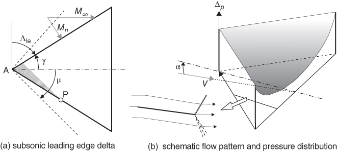
Figure 6.5 Geometry and pressure distribution of a delta wing with subsonic leading edges.
The lift gradient of a delta wing with subsonic leading edges ![]() is obtained from slender wing theory [5]:
is obtained from slender wing theory [5]:
where ![]() denotes the elliptic integral of the second kind with modulus
denotes the elliptic integral of the second kind with modulus ![]() , defined as follows:
, defined as follows:

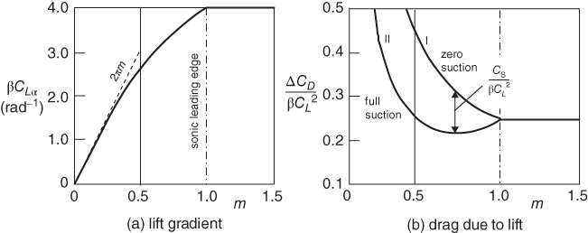
Figure 6.6 Lift gradient and induced drag flat delta wings according to linearized theory.
The following accurate approximation for ![]() is proposed in [19]:
is proposed in [19]:
Figure 6.6(a) suggests that for slender delta wings with ![]() the lift gradient approaches
the lift gradient approaches ![]() and it is worth noting that the lift gradient of a slender wing in subsonic flow is identical to its counterpart with the same aspect ratio in supersonic flow.
and it is worth noting that the lift gradient of a slender wing in subsonic flow is identical to its counterpart with the same aspect ratio in supersonic flow.
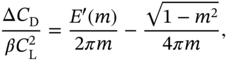
The induced drag due to lift for a subsonic leading edge with zero leading edge suction is derived from Equation (6.7),

Equation (6.10) is depicted in Figure 6.6(b) as curve I. If the full leading edge suction can be realized, the induced drag coefficient is reduced by the suction coefficient,

corresponding to the minimum obtainable induced drag
depicted in Figure 6.6(b) as curve II. As mentioned before, a flat‐plate delta wing is a theoretical concept that will not generate leading‐edge suction. Prediction of the obtainable leading‐edge thrust for practical wing shapes with finite thickness, rounded noses and/or camber is an essential part of aerodynamic design to be treated in Chapter 9.
In the present context reference is made to comprehensive publications such as [19] and [22], whereas the following provisional observations can be useful in the conceptual design stage.
- The favorable effect of suction increases with decreasing
 . However, if no leading‐edge suction is realized, the drag due to lift is doubled for
  .
. - In the design condition the leading edge flow parameter
 is usually in excess of 0.5 and Figure 6.6(b) shows that for
  the drag due to lift is significantly lower for a delta wing with full leading edge suction compared to one with supersonic leading edges. On the provision that the leading edge suction is fully realized, the minimum value of
  is obtained when
 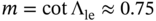 , corresponding to Mach 0.75 normal to the leading edge.
 - In subsonic airflow, the induced drag is inversely proportional to the wing aspect ratio, the essential reason why all subsonic airliners have a high‐aspect‐ratio wing. However, if the equations for linear theory are applied to delta wings with different aspect ratios it is observed that, for flight speeds between Mach 1.2 and 2.0, variation of the aspect ratio has little influence on the drag due to lift for delta wings with full leading edge thrust. This explains to some extent why supersonic cruising aircraft have a low aspect ratio5.
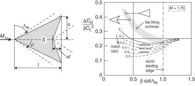
Figure 6.7 Geometry of the flat arrow wing and effect of the notch ratio on the induced drag of arrow wings (after [15]).
6.5 Arrow Wings
Derived from the delta shape, the arrow(head) wing was conceived during the 1970s in the framework of the SCAR research program. The arrow wing is created by a trailing edge cut‐out that deletes part of the delta wing where the generation of lift is less effective, as depicted in Figures 6.4 and 6.5. In the case of notched trailing edges shown in Figure 6.7 the wing geometry is defined by the notch ratio ![]() . For a planform area
. For a planform area ![]() the arrow shape enables the wing's length
the arrow shape enables the wing's length ![]() to be increased, resulting in a reduced pressure drag due to thickness. However, a more prominent advantage of the arrow wing is in the area of induced pressure drag. This is illustrated in Figure 6.7, although it is emphasized that most of the improvements relative to the delta wing are due to twist and camber. This important aspect is subject to treatment in Chapter 9.
to be increased, resulting in a reduced pressure drag due to thickness. However, a more prominent advantage of the arrow wing is in the area of induced pressure drag. This is illustrated in Figure 6.7, although it is emphasized that most of the improvements relative to the delta wing are due to twist and camber. This important aspect is subject to treatment in Chapter 9.
A comparison between delta and arrow wing configurations in [17] designed for cruising at Mach 2.5 shows that the arrow wing design has a lower zero‐lift drag than a delta wing design, which is attributed to a higher wave drag for the supersonic leading edge delta wing and a lower slenderness ratio of its equivalent body. Compared to a delta wing configuration with the same leading edge sweep, the drag reduction of a typical arrow wing amounts to 6.5% for the zero‐lift drag and 15% for the induced drag, resulting in 12% improvement of the aerodynamic efficiency. The overall mission impact for the configuration discussed in [15] is a range improvement of 1,000 km due to the ![]() advantages6.
advantages6.
6.6 Slender Delta and Arrow Wing Varieties
For subsonic as well as supersonic leading edges, two‐dimensional and conical flow regions have the property that the pressure is constant along straight lines through the wing vertex. The numerical analysis in [14] confirms that, independent of the flow parameter ![]() , the center of pressure of a pure delta wing coincides approximately with its center of area located at 2/3 of the root chord downstream from the vertex. For supersonic flow this point is also the aerodynamic center. The backward shift of the aerodynamic center of an airfoil in subsonic flow from 25% of the chord behind the leading edge to the more rearward location at supersonic speed has a significant effect on the stability and control of the aircraft. Accordingly, several modifications of the basic wing have been developed aiming at bringing the aerodynamic center at supersonic speeds more forward.
, the center of pressure of a pure delta wing coincides approximately with its center of area located at 2/3 of the root chord downstream from the vertex. For supersonic flow this point is also the aerodynamic center. The backward shift of the aerodynamic center of an airfoil in subsonic flow from 25% of the chord behind the leading edge to the more rearward location at supersonic speed has a significant effect on the stability and control of the aircraft. Accordingly, several modifications of the basic wing have been developed aiming at bringing the aerodynamic center at supersonic speeds more forward.
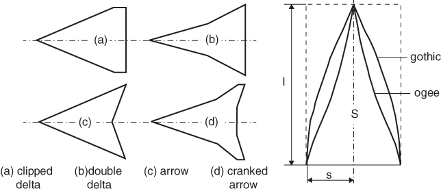
Figure 6.8 Varieties of delta and arrow wings with straight leading edges and delta wing modifications with curved leading edges.
Figure 6.8 illustrates a variety of modifications intended to improve the aerodynamic properties of the delta wing.
- The clipped delta wing has a (small) taper ratio in order to eliminate the inefficient narrow‐chord tip region of the pure delta wing.
- The cranked leading edge of the double delta wing is mainly used to reduce the aerodynamic center movement in the transition from subsonic to supersonic flight.
- The arrow wing with straight leading edges is described in Section 6.5.
- The cranked arrow wing is a further refinement, having an inboard wing with a subsonic leading edge and a (very thin) outboard wing with a supersonic leading edge.
The cranked arrow can profit from the attached flow at the highly swept leading edge. Leading‐edge flaps or a variable nose camber may be used for achieving high aerodynamic efficiency in the operational range of Mach numbers and incidences relative to the flow. This hybrid wing concept is considered to be a promising candidate for a future supersonic commercial transport.
The geometry of slender wings is not restricted to delta shapes with straight leading edges. Figure 6.8 depicts two classes of curved leading edges with streamline tips described in [2].
- The gothic wing has a curved leading edge that remains convex along its length. Its shape is defined as
 , where the local semi‐width is defined as
  .
. - The ogival delta has a leading edge with an inflection point and a shape defined as
 .
.
All slender wings have a pointed apex and the flow around the neighborhood of the apex is approximately conical. This maximizes the suction force on the nose and distributes the lift favorably in a lateral direction, thereby minimizing the drag due to lift.
Bibliography
- 1 Ashley, H., and Landahl M. Aerodynamics of Wings and Bodies. New York: Dover Publications, Inc.; 1965.
- 2 Küchemann, D. The Aerodynamic Design of Aircraft. Oxford: Pergamon Press; 1978.
- 3 Jones, R.T. Wing Theory. Princeton, NJ: Princeton University Press; 1990.
- 4 Anderson, Jr., J.D. Fundamentals of Aerodynamics. 5th ed. New York: McGraw‐Hill; 2010.
- 5 Jones, R.T. Properties of Low‐Aspect Ratio Wings at Speeds Below and Above the Speed of Sound. NACA Report 835; 1946. Available at: http://naca.central.cranfield.ac.uk/reports/1946/naca-report-835.pdf
- 6 Jones, R.T. Wing Plan Forms for High‐Speed Flight. NACA TN 863; 1947. Available at: https://ntrs.nasa.gov/archive/nasa/casi.ntrs.nasa.gov/19930091936.pdf
- 7 Jones, R.T. Estimated Lift‐Drag Ratios at Supersonic Speed. NACA TN 1350; 1947. Available at: https://digital.library.unt.edu/ark:/67531/metadc55497/
- 8 Bonney, E.A. Aerodynamic Characteristics of Rectangular Wings at Supersonic Speeds. J. Aeronautical Sci. 14(2):110–116; 1947.
- 9 Busemann, A. Infinitesimal Conical Supersonic Flow. NACA TM‐1100; 1947. Available at: http://naca.central.cranfield.ac.uk/reports/1947/naca-tm-1100.pdf
- 10 Jones, R.T. The Minimum Drag of Thin Wings in Frictionless Flow. J. Aeronautical Sci. 18(2):75–81; 1951.
- 11 Jones, R.T. Theoretical Determination of the Minimum Drag of Airfoils at Supersonic Speed. J. Aeronautical Sci. 19 (12):813–822; 1952.
- 12 Küchemann, D. Some Considerations of Aircraft Shapes and their Aerodynamics for Flight at Supersonic speeds. Advances in Aeronautical Sciences 3 London: Pergamom Press; 1961. p. 221.
- 13 Stanbrook, A., and Squire L.C. Possible Types of Flow at Swept Wing Leading Edges. The Aeronautical Quarterly, 15(1):72–82; 1964.
- 14 Middleton, W.D., and Carlson H.W. A Numerical Method for Calculating the Flat‐Plate Pressure Distributions on Supersonic Wings of Arbitrary Planform. NASA Technical Note D‐2750, January; 1965.
- 15 Baals, D.D., Robins A.W., and Harris R.V. Aerodynamic Design Integration of Supersonic Aircraft. J. Aircraft. 7(5); 1968.
- 16 Carlson, H.W., and Miller D.S. Numerical Methods for the Design and Analysis of Wings at Supersonic Speeds. NASA Technical Note D‐7713, December; 1974.
- 17 Wright, B.R., Bruckman F. and Radovcich N.A. Arrow Wings for Supersonic Cruise Aircraft. J. Aircraft, 15(12):829–836; 1978.
- 18 Kulfan, R.M., and Sigalla A. Real Flow Limitations in Supersonic Airplane Design AIAA Paper 78‐147, January; 1978. https://doi.org/10.2514/6.1978-147
- 19 Carlson, H.W., and Mack R.J. Estimation of the Leading‐Edge Thrust for Supersonic Wings of Arbitrary Planform. NASA Technical Paper 1270, October; 1978.
- 20 Squire, L.C. Experimental Work on the Aerodynamics of Integrated Slender Wings for Supersonic Flight. Progr. Aerospace Sci. 20(1);1–96; 1981.
- 21 Mattick, A.A., and Stollery J.L. Increasing the Lift: Drag Ratio of a Flat Plate Delta Wing. Aeronautical J. 85(848):379–386; 1981.
- 22 Wood, R.M., and Miller D.S. Impact of Airfoil Profile on the Supersonic Aerodynamics of Delta Wings. J. Aircraft 23(9):695–702; 1986.
- 23 Wood, R.M. Supersonic Aerodynamics of Delta Wings. NASA TP 2771, March; 1988.
Notes
- 1 In fact, it is a sensible aim to keep the whole aircraft well within the Mach cone from its nose.
- 2 The term slender wing can lead to misunderstanding: a slender wing has a low aspect ratio from the aerodynamic point of view, whereas a high aspect ratio wing is considered to have a slender structure.
- 3 The slender wing with near‐triangular planform and sharp leading edges was the most prominent aspect of Concorde's wing.
- 4 Strictly, if a flat wing has a sharp nose, the leading edge flow will separate and the suction force cannot develop, but practical (very thin) wings have some degree of roundness at which a fraction of the suction force may be realized.
- 5 The oblique wing aircraft configuration described in Chapter 10 forms an exception to this rule.
- 6 In principle, this result must be adjusted for the weight fraction differences between the delta and the arrow wing.