
The ability to visualize problems and data can be of great use when trying to understand difficult concepts and, hence, can be of great use to scientists. Perhaps the most obvious application of visualization in science is in the study of molecules, particularly biological molecules. However, a great many other problems can also be elucidated through the use of visualization, particularly real-time and interactive graphics which can go well beyond the capabilities of the previous generation of static, made-for-print graphics.
This chapter introduces two tools that are essential for the development of sophisticated graphical applications on the Windows platform:
Windows Forms for writing graphical user interfaces (GUIs).
Managed DirectX for generating high-performance, real-time and interactive graphics.
These tools are then used to develop a library that allows easy-to-use graphical applications to be spawned seamlessly from the F# interactive mode, and an example stand-alone graphical application for visualizing scientific data.
Several of the complete example programs presented in chapter 12 use the scene graph library developed in this chapter.
A great deal is expected of modern computer programs. They should provide a graphical user interface that presents the necessary information to the user in a clear and comprehensible way.
Fortunately, Windows Forms provides an easy way to create graphical user interfaces. Using Visual Studio, GUIs can be designed using drag and drop and the generated C# code can be edited to provide the necessary functions, responding to events such as button clicks in order to provide the required interface. In many cases, only a simple GUI is required and, in such cases, this can be achieved without the benefit of a GUI designer.
This section explains how simple GUIs can be created by writing only F# code. In particular, how GUIs can be spawned from the F# interactive mode in order to test and tweak them.
The most fundamental construct in Windows Forms is the form. Definitions provided by .NET that are related to Windows Forms are in the namespace:
> open System.Windows.Forms;;
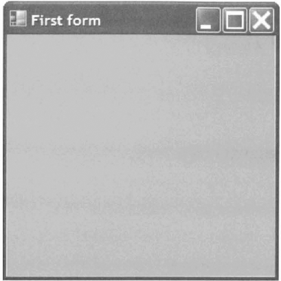
A blank form can be created by a single line of code, calling the constructor of the .NET Form class and setting some properties of the form to make it visible and give it a title:
> let form = new Form(Visible=true, Text="First form");;
val form : Form
The resulting form is shown in figure 7.1.
Setting the TopMost property ensures that the form stays as the top-most window:
> form.TopMost <- true;;
val it : unit = ()
This is useful when developing applications from the F# interactive mode, as the interactive session can be used to develop the form that is shown on top.
Graphical user interfaces inside forms are composed of controls, such as labels, text boxes and even web browsers. The layout of controls on a form is often a function of the size of the form. The size of a form is accessible in two different ways. The total size of the form including window decorations (the title bar, scroll bars and so on) can be obtained using:
> form.Size;;
val it : Size = {Width=300, Height=300} ...
The area available for controls is often a more important quantity and is called the client rectangle. The size of the client rectangle is slightly smaller than the size of the entire form:
> form.ClientSize;;
val it : Size = {Width=292, Height=260} ...
In order to make a useful GUI, controls must be added to the form.
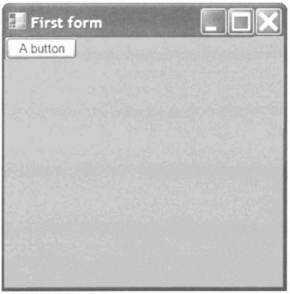
Creating and adding controls to forms is also easy. A control is created by calling the appropriate constructor, for example a button:
> let button = new Button(Text="A button");;
val button : Button
The control can then be added to the form using the form's Controls .Add member:
> form.Controls.Add(button);;
val it : unit = ()
The resulting form is shown in figure 7.2.
For a suite of controls laid out on a form to be useful, the controls must be connected to functions that are executed when events occur, such as the clicking of a button. This is achieved by adding functions as event handlers.
The button in the previous example does nothing when it is clicked. To make the button click perform an action, a function called an event handler must be added to the button.Click event. In F#, the event handler can be an anonymous function. For example, to close the form when the button is clicked:
> button.Click.Add(fun _ -> form.Close());;
val it : unit = ()
Constructing controls and registering event handlers in this style allows GUIs to be composed with relative ease and, in particular, to be developed from an F# interactive session.
Before delving into fully-fledged DirectX programming, it is worth taking a peek at the functionality provided by simple bitmaps rendered using Windows Forms. Bitmaps can be used to render a variety of simple, raster-based images. In this section we shall outline a simple programmatic bitmap renderer before using it to render a cellular automaton.
Many relevant definition are in the following namespaces:
> open System;;
> open Drawing;;
> open Windows.Forms;;
In this case, the bitmap will have 24 bits-per-pixel (bpp):
> let format = Imaging.PixelFormat.Format24bppRgb;;
val format : Imaging.pixelFormat
A bitmap can be created to cover the client area of a form and filled using the given function f:
> let bitmap_of f (r : Rectangle) =
    let bitmap = new Bitmap(r.Width, r.Height, format)
    f bitmap
    bitmap;;
val bitmap_of : (Bitmap -> unit) -> Rectangle -> Bitmap
An event handler can used used to replace the bitmap when the size of the form changes:
> let resize f (b : Bitmap ref) (w : #Form) _ =
    b := bitmap_of f
    w.ClientRectangle w.Invalidate ();;
val resize :
  (Bitmap -> unit) -> Bitmap ref -> #Form -> 'b -> unit
An event handler can be used to draw the bitmap into the window:
> let paint (b : Bitmap ref) (v : #Form)
      (e : PaintEventArgs) =
    let r = e.ClipRectangle
    e.Graphics.DrawImage(!b, r, r, GraphicsUnit.Pixel);;
val paint :
  Bitmap ref -> #Form -> PaintEventArgs -> unit
The following function creates a form, a bitmap and registers handlers for resizing, painting and key press (to close the form if the escape key is pressed):
> let make_raster f =
    let form = new Form(Visible=true)
    let bitmap = ref (bitmap_of f form.ClientRectangle)
    form.Resize.Add(resize f bitmap form)
    form.Paint.Add(paint bitmap form)
    form.KeyDown.Add(fun e ->
      if e.KeyCode = Keys.Escape then form.Close())
    form;;
val make_raster : string -> (Bitmap -> unit) -> Form
The make_raster function can be used as the basis of many programs that require simple bitmap output. Rendering is left entirely up to the user using the function f to draw into the bitmap as necessary.
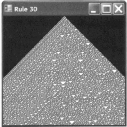
One application ideally suited to rendering into bitmaps is cellular automata. In Stephen Wolfram's seminal work "A New Kind of Science", he studies a simple but remarkably unpredictable 1D cellular automaton called rule 30 where each generation is a row of cells that are in one of two states.
The two states of a cell may be represented by a variant type:
> type cell = A | B;;
A rule computes the state of a cell in the next generation given the state of the cell and its two neighbours in the current generation. Rule 30 may be written:
> let rule30 a b c =
    match a, b, c with
    | B, B, _ | B, A, B | A, A, A -> A
    | _ - > B;;
val rule30 : cell -> cell -> cell -> cell
A generation may be evolved into the next generation by mapping a rule over triples of neighbouring cells in the current generation, assuming cells outside to be in the state A:
> let rec evolve_aux rule = function
    | a::(b::c::_ as t) ->
        rule a b c :: evolve_aux rule t
    | [a; b] -> [rule a b A; rule b A A]
    | [a] -> [rule A a A; rule a A A]
    | [] -> [rule A A A];;
val evolve_aux :
  (cell -> cell -> cell -> 'a) -> cell list -> 'a list
The auxiliary function evo1ve_aux that computes the next generation is finished by prepending the left-most cell and padding the previous generation with a cell in state A before passing it to the evolve_aux function:
> let evolve rule list =
    evolve_aux rule (A :: A :: list);;
val evolve :
  (cell -> cell -> cell -> 'a) -> cell list -> 'a list
Cells in state A will be drawn in white and cells in state B will be drawn in black:
> let color_of_cell = function
    | A -> Color.White
    | B -> Color.Black;;
val color_of_cell : cell -> Color
A single cell is drawn by shifting the x coordinate to "grow" the generations from the center of the bitmap and filling the pixel if it is visible:
> let set (bitmap : Bitmap) y x c =
    let x = bitmap.Width / 2 - y + x
    if 0 <= x && x < bitmap.Width then
      bitmap.SetPixel(x, y, color_of_cell c);;
val set : Bitmap -> int -> int -> cell -> unit
The whole bitmap is drawn by evolving a generation for each row and filling each cell in each row:
> let draw rule bitmap =
    let aux gen y =
      List.iteri (set bitmap y) gen
      evolve rule gen
    ignore (Seq.fold aux [B] {0 .. bitmap.Height - l});;
val draw :
  (cell -> cell -> cell -> cell) -> Bitmap -> unit
Finally, a form rendering this bitmap may be created using the make_raster function defined in the previous section:
> let form = make_raster (draw rule30);;
val form : Form
The resulting visualization is illustrated in figure 7.3.
if the above code is compiled into an application and run the program will quit immediately and close the window. To get the desired behaviour, the main thread of the program should block until the form is closed. This is achieved by calling the Application.Run function.
if a program spawns a single window, or if there is a clear master window in the GUI design, a compiled application may block until a specific form is closed by calling:
Application.Run(form)
where form is the master window.
Alternatively, the App lication.Exit function may be used to exit a program explicitly. Such a program can be run by supplying the value of type unit to the Run member, rather than a form:
Application.Run()
In many cases it is desirable to provide an F# program such that it can be executed either from an interactive session or compiled into a program and run. In such cases, the # if preprocessor directive can be used to select code depending upon the way in which the program is run by testing either COMPILED or INTERACTIVE:
#if COMPILED
Application.Run(form)
#endif
This allows identical code to be used both in the interactive mode and compiled to standalone executable.
More advanced applications require the ability run separate windows concurrently. This requires the use of threading and will be discussed in more detail later in this chapter, in the context of spawning visualizations from F# interactive sessions, in section 7.2.5.
The defacto standard for high-performance graphics on the Windows platform is DirectX. Microsoft provide a high-level interface to DirectX from .NET, known as Managed DirectX.
Despite being a high-level interface, programs using Managed DirectX must contain a significant amount of "boiler plate" code that is required to get anything working. This common code is presented here in the form of a reusable library written in F# that allows visualizations to be spawned from the F# interactive mode.
All programs that use DirectX must begin with declarations to include the appropriate directory:
> #I @"C:WINDOWSMicrosoft.NETDirectX for Managed
Codel.0.2902.0";;
and import the relevant DLLs:
> #r @"Microsoft.DirectX.dll";;
> #r @"Microsoft.DirectX.Direct3D.dll";;
> #r @"Microsoft.DirectX.Direct3DX.dll";;
Graphics-related functions make heavy use of several namespaces, which can be productively opened to improve clarity:"
> open System;;
> open Drawing;;
> open Windows.Forms;;
> open Microsoft.DirectX;;
> open Direct3D;;
The properties of a DirectX device are dictated by a set of present parameters[17]:
> let presentParams() =
    let p = new PresentParameters(Windowed=true)
    p.SwapEffect <- SwapEffeet.Discard
    p.EnableAutoDepthStencil <- true
    p.AutoDepthStencilFormat <- DepthFormat.D24S8
    [| P |];;
val presentParams : unit -> PresentParameters array
A DirectX device with these present parameters can be created by calling the constructor of the Device class:
> let make_device (form : #Form) =
    let dtype = DeviceType.Hardware
    let flags = CreateFlags.HardwareVertexProcessing
    new Device(0, dtype, form, flags, presentParams());;
val make_device : #Form -> Device
As .NET libraries such as DirectX are written in an object oriented style, this style can be adopted in the F# code that interfaces with these libraries. In this case, a minimal Viewer class is used to provide a form with no background using the implicit-constructor form of class declaration described in section 2.4.2.2:
> type Viewer() =
    inherit Form()
    override form.OnPaintBackground _ = ();;
In effect, we shall be specializing the Form class in order to implement the functionality of a DirectX viewer. However, rather than adopting the C# style of writing one large class, we shall instead opt to develop several small functions that can be retrofitted onto this minimal Viewer class to provide the desired functionality.
A higher-order paint callback can be used to perform mundane tasks including calling the render function to render the scene, which is passed as an argument to paint:
> let paint (form : #Form) render (device : Device) _ =
    try
      device.TestCooperativeLevel()
      device.BeginScene()
      render device
device.EndScene()
device.Present()
form.Invalidate()
with
| :? DeviceLostException -> ()
| :? DeviceNotResetException ->
device.Reset(presentParams()),-;;
val paint :
#Form -> (Device -> unit) -> Device -> 'b -> unitNote the use of the : ? construct to handle exceptions generated outside F#.
The complexity of this paint function is due to the fact that managed DirectX requires us to handle situations where the DirectX device is left corrupted by another application (a device reset) or lost entirely.
A Viewer object and DirectX device can be created and initialized using a higher-order make_viewer function:
> let make_viewer title render =
    let form = new Viewer(Text=title, Visible=true)
    form.MinimumSize <- form.Size
    let device = make_device form
    form.Paint.Add(paint form render device)
    form.Resize.Add(fun _ -> form.Invalidate())
    form.KeyDown.Add(fun e ->
      if e.KeyCode = Keys.Escape then form.Close())
    form.Invalidate()
    form;;
val make_viewer : string -> (Device -> unit) -> Viewer
This function is careful to constrain the minimum size of the window because managed DirectX will crash if a device is shrunk too much.
By default, the contents of a window are redrawn when the window is enlarged but not when it is shrunk. In order to redraw the window whenever it is resized, the Resize event is made to invalidate the form. The KeyDown event is used to close the form if the escape key is pressed.
A minimal DirectX Tenderer that simply clears the display to a specified color can now be run from only 3 lines of code. The render function clears the target buffer of the device to a given color:
> let render (device : Device) =
    let target = ClearFlags.Target
    device.Clear(target, Color.Coral, l.f, 0);;
val render : Device -> unit
The make_viewer function can then be used to create a blank form by providing the title and render function:
> let form = make_viewer "Blank" render;;
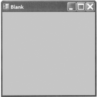
val form : Viewer
The resulting window is illustrated in figure 7.4.
DirectX is designed for programmatic rendering, where programs explicitly invoke the DirectX API to get a scene rendered. This section describes how the DirectX API can be invoked directly from F# code. Programmatic rendering has the advantage that all aspects of rendering can be completely controlled and, consequently, programs can be tweaked to improve performance. Later in this chapter, we shall introduce a simpler way to visualize data using declarative rendering from an F# interactive session.
In the simplest case, programmatic rendering can be broken down into per-pixel buffers, vectors, vertices, projections, views and the rendering of primitives. Each of these topics will now be discussed before moving onto more sophisticated subjects.
A DirectX device provides up to three different kinds of pixel buffer: the target buffer for pixel colors, the z-buffer to store depth values and the stencil buffer for per-pixel clipping. The paint event will almost always clear all three buffers and, consequently, it is useful to factor out a value representing all three buffers:
> let all_buffers =
    Enum.combine
      [ ClearFlags.Target;
        ClearFlags.ZBuffer;
        ClearFlags.Stencil];;
val all_buffers : ClearFlags
This value will be used in future functions.
The native 64-bit float type of F# is more accurate than the native 32-bit format of DirectX (f loat32). Trading performance for simplicity, the DirectX Vector3 type can be constructed using an F# function that handles float values:
> let vec (x, y, z) =
    let f = Float32.of_float
    new Vector3(f x, f y, f z);;
val vec : float * float * float -> Vector3
In the interests of simplicity, we shall use a single Vertex type that encapsulates the coordinate, normal vectorz and color information for every vertex:
> type Vertex = CustomVertex.PositionNormalColored;;
An F#-friendly constructor for the Vertex type may be written in curried form:
> let vertex (c : Color) (nx, ny, nz) (x, y, z) =
    let c = c.ToArgb()
    let f = Float32.of_float
    new Vertex(f x, f y, f z, f nx, f ny, f nz, c);;
val vertex :
  Color -> (float * float * float) ->
    (float * float * float) -> Vertex
The order of the parameters to the curried vertex function have been chosen such that partial application of this function is as useful as possible. Specifically, whole objects are likely to share a single color, which can be partially applied first. Individial faces may be composed of several triangles sharing a single normal vector, which can be partially applied next. Finally, the vertex coordinate is applied to obtain a Vertex value.
The following function creates a Vertex from two coordinates:
> let vertex2 color (x, y) =
    vertex color (0.0, 0.0, −1.0) (x, y, 0.0);;
val vertex2 : Color -> float -> float -> Vertex
These functions will be used to compose programs that render geometry using DirectX.
An orthographic projection can be used to visualize 2D scenes. The following show2d combinator initializes an orthographic projection before callingthe given render function:
> let show2d render (device : Device) =
    let near, far = -l.Of, l.Of
let vp = device.Viewport
let w, h = float32 vp.Width, float32 vp.Height
device.Transform.Projection <-
Matrix.OrthoLH(w, h, near, far)
device.Clear(ClearFlags.Target, Color.White, far, 0)
device.RenderState.Lighting <- false
device.RenderState.CullMode <- Cull.None
device.RenderState.ZBufferEnable <- false
render device;;
val show2d : (Device -> unit) -> Device -> unitThis combinator sets the near and far clipping planes to z = —1 and z = 1, respectively, in anticipation of vertex coordinates on the plane z = 0. The viewport is set to ±w/2 and ±h/2 where w and h are the width and height of the DirectX device (the whole of the client rectangle of the window), i.e. the coordinates in the scene are measured in pixels and the origin is the center of the window. The buffers are cleared and lighting and culling are disabled before the render function is called to render the current scene.
As DirectX is primarily used to render 3D scenes that often contain closed meshes of triangles, it provides the ability to neglect triangles that are back-facing as an optimization. A triangle is deemed to be back-facing or front-facing depending on whether its vertices are listed in clockwise or counter-clockwise order from the point of view of the camera. In the 2D case, this backface culling is not usually useful, so our show2d combinator disables this default behaviour.
Rendering graphics in 3D is only slightly more difficult than the 2D case but is often more useful. Setting up 3D visualization typically requires perspective projection and lighting. This section defines several functions that can be used to simplify the task of programming 3D graphics in F#.
The aspect ratio of the display must be determined in order to create a 3D perspective projection. This can be obtained via the viewport of the DirectX device using the following function:
> let aspect (device : Device) =
    let vp = device.Viewport
    float32 vp.Width / float32 vp.Height;;
val aspect : Device -> float32
A perspective projection is quantified by a field of view (FOV), the distances of near and far clipping planes from the camera and the positions of the camera, target (that the camera points at) and the up-direction of the camera:
> type perspective =
    {
      fov: float32;
      aspect: float32;
      near: float32;
far: float32;
camera: Vector3;
target: Vector3;
up: Vector3;
};;We shall use the following default values:
> let perspective_default =
    { fov = 0.8f; aspect = O.Of;
      near = O.Olf; far = 100.Of;
      camera = vec(-1.0, 2.0, −4.0);
      target = vec(0.0, 0.0, 0.0);
      up = vec(0.0, 1.0, 0.0) };;
val perspective_default : perspective
The following function sets a perspective projection and view in the DirectX device:
> let perspective p (t : Transforms) =
    t.Projection <-
      Matrix.PerspectiveFovLH(p.fov, p.aspect,
                              p.near, p.far)
    t.View <-
      Matrix.LookAtLH(p.camera, p.target, p.up);;
val perspective : perspective -> Transforms -> unit
The Projection and View matrices of the DirectX device are setup by the show3d combinator before it calls the given render function:
> let show3d render (device : Device) =
    let p = { perspective_default with
                aspect = aspect device }
    perspective p device.Transform
    device.Clear(all_buffers, Color.White, p.far, 0)
    device.Lights. [0] .Direction <- vec(1.0, −1.0, 2.0)
    device.Lights. [0].Enabled <- true
    render device;;
val show3d : (Device -> unit) -> Device -> unit
This function is suitable for displaying objects at the origin and of roughly unit radius. A single light is set. Note that culling defaults to backface culling, so triangles are only visible from one side.
In order to render a 2D or 3D scene it is necessary to provide the show2d or show3d functions with a render function that can render primitives onto the device.
Modern graphics hardware is capable of rendering a variety of primitives (see figure 7.5). All non-trivial objects, such as spheres and cylinders, must be approximated using these primitives.
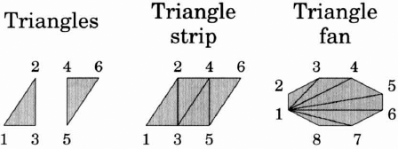
Figure 7.5. Abutting triangles can be amortised into triangle fans and strips to reduce the number of vertices required to describe a geometry.
Triangle strips and fans are used as more space efficient representations of abutting triangles, requiring n+2 vertices to describe n triangle rather than 3n vertices required when triangles are specified individually. Although this is a productive optimization, we shall restrict ourselves to the rendering of individual triangles in this chapter in the interests of simplicity.
Table 7.1. DirectX primitive drawing functions.
Direct from vertex array | Indirected through index array | |
|---|---|---|
Ordinary arrays |
|
|
Compiled arrays |
|
|
Primitives can be drawn by calling one of several members of the Device class:
DrawUserPrimitivesDrawIndexedUserPrimitivesDrawPrimitivesDrawIndexedPrimitives
These four functions have different properties (see Table 7.1).
The DrawUserPrimitives and DrawIndexedUserPrimitives functions render primitives from a vertex array specified as a native .NET (or F#) array. These functions are less efficient but easier to use.
The DrawPrimitives and DrawIndexedPrimitives functions render primitives from compiled vertex arrays. These functions are more efficient but more complicated and harder to use. Specifically, these functions require the vertex array to be in a compiled form and, in particular, the properties of the compiled form can be set such that the vertex data actually resides on the graphics card, dramatically increasing performance for static vertex data.
In the interests of simplicity, we shall use only the DrawUserPrimitives function in the remainder of this chapter.
The F# programming language can provide more compile-time assurances than the Managed DirectX API currently provides. Specifically, the vertex and index data passed to these functions is not statically typed. In order to catch errors at compile time, we shall wrap the DrawUserPrimitives function in a statically typed function to render individual triangles:
> let draw_triangles (device : Device)
      (vertex : Vertex array) =
    device.VertexFormat <- Vertex.Format
    let prim = PrimitiveType.TriangleList
    let n = Array.length vertex / 3
    device.DrawUserPrimitives(prim, n, vertex);;
val draw_triangles : Device -> Vertex array -> unit
This function expects a vertex array containing 3n vertices, 3 for each of n triangles.
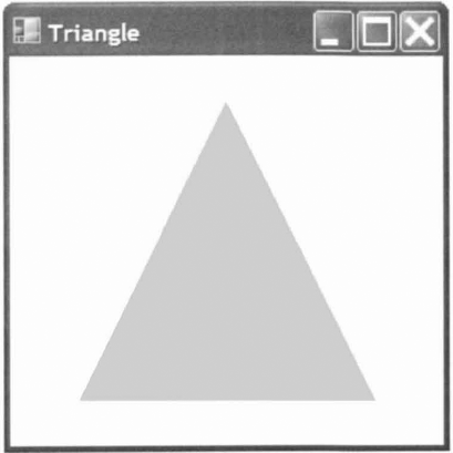
A window visualizing a triangle can be spawned from the F# interactive mode with:
> let form =
    let render device =
      [| −100.0, −100.0; 0.0, 100.0; 100.0, −100.0 |]
      |> Array.map (vertex2 Color.BurlyWood)
      |> draw_triangles device
    show2d render
    |> make_viewer "Triangle";;
val form : Form
The result is illustrated in figure 7.6.
The 12 vertices of an icosahedron are given by:
> let vertices =
    let r, y = sin(Math.PI / 3.0), cos(Math.PI / 3.0)
    let f g x = r * g(float x * Math.PI / 5.0)
    let aux n y i =
      vec(f sin (2*i + n), y, f cos (2*i + n)))
    Array.concat
      [ [|vec (0.0, 1.0, 0.0) |];
        Array.init 5 (aux 0 y);
        Array.init 5 (aux 1 (-y));
        [|vec(0.0, −1.0, 0.0)|]];;
val vertices : Vector3 array
The 20 triangular faces of an icosahedron are given in terms of those vertices by:
> let faces =
let r1 i = 1 + (1 + i) % 5
    let r2 i=6+ (1+i) % 5
    [for i in 0 .. 4 -> 0, rl i, rl(i + 1)] @
    [for i in 0 .. 4 -> rl(i + 1), rl i, r2 i] @
    [for i inO ..4->rl(i+l), r2 i, r2(i + 1)] @
    [for i in 0 .. 4 -> r2(i + 1), r2 i, 11];;
val faces : (int * int * int) list
The following tri_of _f ace function converts the color and vertices of a triangular face from the icosahedron into a vertex array ready for rendering:
> let tri_of_face (c : Color) (v : Vector3 array)
      (i, j. k) =
    let i, j, k = v. [i] , v. [j] , v. [k]
    let n = Vector3.Normalize(i + j + k)
    let v r = new Vertex(r, n, c.ToArgb())
    [| V i; V j; V k |];;
val tri_of_face :
  Color -> Vector3 array -> int * int * int ->
    Vertex list
A complete vertex array for the icosahedron may then be created by concatenating the result of mapping the tri_of _f ace function over the faces of the icosahedron:
> let triangles =
    faces
    |> List.map (tri_of_face Color.BurlyWood vertices)
    |> Array.concat;;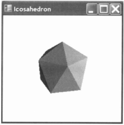
val triangle : Vertex array
This demo can be animated to make it more interesting. The simplest way to define an animation in a functional programming language is to make the scene a function of time. The elapsed time can be obtained from a running stopwatch:
> let timer = new System.Diagnostics.Stopwatch();;
val timer : Diagnostics.Stopwatch
> timer.Start();;
The rendering function simply sets the world transformation matrix to a rotation about the y -axis and then draws the triangles from the vertex array:
> let render_icosahedron (device : Device) =
    let t = float32 timer.ElapsedMilliseconds / le3f
    device.Transform.World <- Matrix.RotationY t
    draw_triangles device triangles;;
val render_icosahedron : Device -> unit
The make_viewer function and show3d combinator may then be used to visualize the icosahedron:
> let form =
    show3d render_icosahedron
    |> make__viewer "Icosahedron";;
val form : Viewer
The result is illustrated in figure 7.7.
As this example has demonstrated, animated 3D graphics can be visualized with little effort in F#. However, these examples used F# code to render a scene programmatically. Visualizations typically have so much in common that the only variable is the data itself. Consequently, declarative rendering is prolific in scientific computing.
A scene can be represented by a single value, a data structure, that conveys all of the necessary information about the positions and colors of triangles in the scene. This allows scenes to be visualized without any programming. In a functional language, the value representing a scene may contain functions and, in particular, may be a function of time to facilitate animation.
This section describes additional code that can be used to allow real-time, animated 2D and 3D graphics to be visualized as easily as possible from the F# interactive mode, by describing scenes as values. Although this is a comparatively small amount of library code, the functionality of the library actually exceeds the functionality provided by several expensive commercial packages.
The type of value used to represent a scene is known as a scene graph.
In F#, a variant type can be used to represent a scene:
> type scene =
    | Triangles of (Vector3 * Vector3 * Vector3) list
    | Color of Color * scene
    | Transform of Matrix * scene
    | Group of scene list;;
In this case, there are four different kinds of scene graph node. The Triangles constructor represents a set of triangles as a list of 3-tuples of 3D vectors. The Color constructor allows the color of triangles given in the child scene to be overriden. The Transform constructor allows a matrix transformation (such as a rotation or scaling) to be applied to the child scene. Finally, the Group constructor allows separate scenes to be composed.
A simple scene containing a single triangle can now be described very succinctly in terms of the scene variant type:
> Triangles
    [ vec(-1.0, 0.0, 0.0) ,
      vec (0.0, 1.0, 0.0),
      vec(1.0, 0.0, 0.0)];;
val it : scene = Triangles ...
As we shall see, the ability to visualize a scene defined in this way is extremely useful, particularly in the context of scientific computing.
In the interests of generality, we shall continue to use the Vert ex type that includes position, normal and color information for every vertex. However, the scene type does not allow normal vectors and colors to be defined per vertex.
The following function converts a triangle from the scene graph representation into a vertex array suitable for rendering:
> let triangle (c : Color) (pO, p1, p2) =
    let pOl, p02 = p1 - pO, p2 - pO
    let n = Vector3.Normalize(Vector3.Cross(pOl, p02))
    Array.map (vertex c n) [| p0; p1; p2|];;
val triangle :
  Color -> Vector3 * Vector3 * Vector3 -> Vertex array
A Trans form node of a scene can be rendered using a combinator that multiplies the current World transformation matrix by the transformation matrix m of the node, calls the given function k and restores the World matrix before returning:
> let transform (device : Device) color m k scene =
    let world = device.Transform.World
    device.Transform.World <- Matrix.Multiply(world, m)
    try k device color scene finally
    device.Transform.World <- world;;
val transform :
  Device -> 'a -> Matrix ->
    (Device -> 'a -> 'b -> unit) -> 'b -> unit
The draw_triangles and transform functions can be used to draw an arbitrary scene:
> let rec draw (device : Device) color = function
    | Triangles tris ->
        Array.concat (List.map (triangle color) tris)
        |> draw_triangles device
    | Color(color, scene) -> draw device color scene
    | Transform(m, scene) ->
        transform device color m draw scene
    | Group ts -> List.iter (draw device color) ts;;
val draw : Device -> Color -> scene -> unit
Note that the draw function passes itself to the trans form combinator in order to recurse through a Transform node in the scene graph.
In most cases, this library will be unnecessarily inefficient. However, modern graphics hardware is very fast and will be more than capable of rendering quite complicated scenes using this library.
Declarative scene graphs are most useful if the F# interactive mode is made to spawn a new window visualizing the scene whenever a computation results in a value of the type scene. This effect can be achieved by supplementing a running F# interactive session with pretty printers that spawn a separate thread to handle the visualization of a value. Threading is essential here to ensure that separate visualizations run concurrently. If visualizations are not spawned on separate threads then unwanted interactions between visualizations will occur, such as only the window in focus being refreshed. Threading is discussed in much more detail in section 9.3.
The following function spawns a window visualizing a scene:
> let printer scene =
    let thread =
      new System.Threading.Thread(fun () ->
        (fun device -> draw device Color.Black scene)
        |> show3d
        |> make__viewer "F# visualization"
        |> Application.Run)
    thread.SetApartmentState(ApartmentState.STA)
    thread.Start()
    "<scene>";;
val animated_printer : (unit -> scene) -> string
The first definition nested inside this printer function defines a variable thread that is an unstarted thread. When the thread is started (in the penultimate line), a new concurrent thread of execution will be created and the body of the anonymous function that was passed to the Thread constructor will be evaluated in that new thread of execution. This body creates a new Viewer object and uses the Run member to start a Windows Forms message loop and run the form as an application.
This formulation is absolutely essential for the correct working of the printer function because a Windows form must only be accessed directly from the thread on which it was created. If the form is accidentally created on the current thread but accessed on the new thread (including being passed to the Run member) then the program will not achieve the desired effect.
The next line requests that the new thread uses single-threaded apartment state, which is a requirement of a Windows form. The thread is then started and the " scene" string is returned for the interactive session to print.
The printer function can be registered with an F# interactive session using the AddPrinter method of the f si object:
> fsi.AddPrinter(printer);;
Any expressions entered into the F# interactive mode that evaluate to a value of the type scene such that the F# interactive mode tries to print the value now results in a new window being spawned that visualizes the value.
Entering a value of the type scene now spawns a new window visualizing the scene, such as the black triangle in the following example:
> Triangles
    [ vec(-1.0, −1.0, 0.0) ,
      vec(0.0, 1.0, −1.0),
      vec (1.0, −1.0, 0.0)];;
val it : scene = <scene>
Writing functions to generate and manipulate scene graphs is much easier than writing correct programmatic renderers. The remainder of this chapter demonstrates some of the many ways that this simple library can be leveraged to produce useful visualizations.
In the general case, mathematically-simple objects, such as spheres, are remarkably difficult to render on modern graphics hardware.
When visualizing a biological molecule, each atom might be represented by an individual sphere. There are likely to be tens of thousands of such spheres in a single image. Consequently, each sphere must be decomposed into only a few triangles, or the graphics system will be overwhelmed and the visualization will be too slow. A simple tesselation, such as an icosahedron may well suffice in this case.
In contrast, a cartographic application might use a single sphere to represent an entire planet. The single sphere must be decomposed into many triangles for the resulting tesselation to be accurate enough to give the illusion of being a sphere. However, the sphere cannot be uniformly subdivided, or the tesselation will contain too many triangles on the far side of the sphere and too few on the near side. Thus, this application requires an adaptive tesselation, where the sphere is decomposed into triangles as a function of the view of the sphere that is required.
In this book, we shall consider only simple, uniform tesselations that suffice for the required applications. Objects such as circles and spheres can be uniformly tesselated easily. Moreover, the task of subdividing coarse meshes to obtain more accurate meshes is ideally suited to recursive functions. As we shall see, many topics in computer graphics can be solved elegantly and succinctly in F#.
Spheres can be tesselated by recursively subdividing the triangular faces of an icosahedron and pushing new vertices out onto the surface of the sphere.
First, we extract the faces of an icosahedron as a list of 3-tuples of vectors:
> let triangles =
    [ for i, j, k in faces ->
        vertices.[i], vertices . [j] , vertices. [k]];;
val triangles : (Vector3 * Vector3 * Vector3) list
The following function splits an edge by averaging the end coordinates and normalizing the result to push the new vertex out onto the surface of the unit sphere:
> let split_edge(p, q) =
    Vector3.Normalize((p + q) * 0.5f);;
val split_edge : Vector3 * Vector3 -> Vector3
The following function splits a triangular face into four smaller triangles by splitting the three edges:
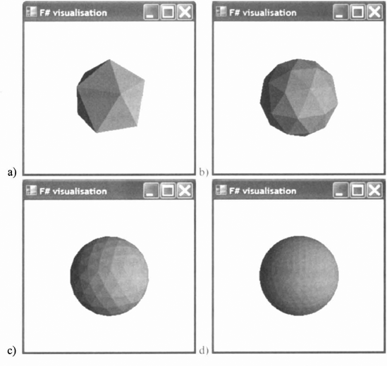
Figure 7.8. Progressively more refined uniform tesselations of a sphere, obtained by subdividing the triangular faces of an icosahedron and normalising the resulting vertex coordinate vectors to push them onto the surface of a sphere.
> let split_face t (a, b, c) =
    let d = split_edge(a, b)
    let e = split_edge(b, c)
    let f = split_edge(c, a)
    [a, d, f; d, b, e; e, c, f; d, e, f];;
val split_face :
  (Vector3 * Vector3 * Vector3) ->
    (Vector3 * Vector3 * Vector3) list
Mapping the split_face function over a sequence of triangles subdivides a coarse tesselation into a finer one:
> let subdivide triangles =
    List.flatten(List.map split_face triangles);;
val subdivide :
  (Vector3 * Vector3 * Vector3) list ->
    (Vector3 * Vector3 * Vector3) list
Finally, the following function returns the nth tesselation level of asphere as a list of triples of vertex coordinates using the nest combinator from section 6.1.1:
> let sphere n =
    nest n subdivide triangles;;
val sphere : int -> (Vector3 * Vector3 * Vector3) list
The following expression spawns four visualizations of progressively more refined tesselations of a sphere:
> [ for n in 0 .. 3 ->
      Color(Color.Salmon, Triangles(sphere n))];;
val it : (unit -> scene) list
  = [<scene>; <scene>; <scene>; <scene>]
The resulting visualizations are illustrated in figure 7.8.
A function of two variables can be tesselated into a 3D mesh of triangles using a variety of different techniques. The simplest approach is to uniformly sample the function over a grid and convert each grid square into a pair of triangles.
The following higher-order plot function samples a function f over a continuous range [x0, x1] and [z0, z1] to generate a scene graph ready for rendering:
> let plot n f xO xl zO zl =
    let g i j =
      let x = xO + (xl - xO) * float i / float n
      let z = zO + (zl - zO) * float j / float n
      vec (x, f x z, z)
    [for i in 0 .. n-1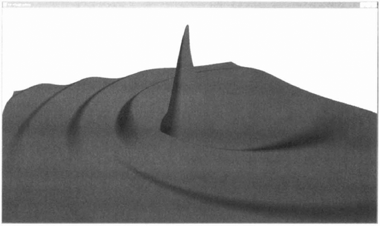
for j in 0 .. n-1 ->
          let h n m = g (i + n) (j + m)
          [h O O, h O l, h 1 l; h O O, h 1 l, h l O]]
    |> List.flatten
    |> Triangles;;
val plot :
  int -> (float -> float -> float) -> float -> float ->
    float -> float -> scene
The following example function represents
> let f x z =
    let r = 5.0 * sqrt(x * x + z * z)
    sin(r + 3.0 * x) / r;;
val f : float -> float -> float
This function f can be tesselated and visualized by applying it to the plot function with suitable parameters:
> Color(Color.Red, plot 255 f −3.0 3.0 −3.0 3.0);;
val it : unit -> scene = <scene>
The result is illustrated in figure 7.9.
The samples provided in this chapter illustrate the basic use of Windows Forms and Managed DirectX for visualization. This allows simple visualizations to be created and even spawned independently from F# interactive sessions. However, the construction of a library capable of abstracting away the complexity involved in optimizing scene graphs and all threading issues when simulations are to be performed concurrently with visualizations is substantially more difficult. Fortunately, this has already been done by the commercial "F# for Visualization" library from Flying Frog Consultancy. One of the complete examples with visualizations from chapter 12 will use this library.
[17] Note that the homonym "present" in the context of DirectX typically means "show" rather than "now".