REVIEWING THE BASICS
RESISTORS
Resistors limit the flow of electrical current. A resistor has a resistance (R) of 1 ohm if a current (I) of 1 ampere flows through it when a potential difference (E) of 1 volt is placed across it. In other words:
![]()
These handy formulas form Ohm’s law. Memorize them. You will use them often.
Resistors are identified by a color code:
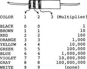
A fourth color band may be present. It specifies the tolerance of the resistor. Gold is ± 5% and silver is ± 10%. No fourth band means ± 20%.
Since no resistor has a perfect tolerance, it’s often okay to substitute resistors. For example, it’s almost always okay to use a 1.8K resistor in place of a 2K unit. Just try to stay within 10-20% of the specified value.
What does K mean? It’s short for 1,000. 20K means 20 × 1,000 or 20,000 ohms. M is short for meg-ohm or 1,000,000 ohms. Therefore a 2.2M resistor has a resistance of 2,200,000 ohms.
Resistors which resist lots of current must be able to dissipate the heat that’s produced. Always use resistors with the specified power rating. No power rating specified? Then it’s usually okay to use 1/4 or 1/2 watt units.
Almost every electronic circuit uses resistors. Here are three of the most important applications for resistors:
1. Limit current to LEDs, transistors, speakers, etc.
2. Voltage division. For instance:
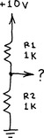
The voltage at ? is I × R2. I means the current through R1 and R2. So I = 10/(R1 + R2) or 0.005 amperes.
Therefore, ? = (0.005) × (1000) or 5 volts.
Note that the total resistance of R1 and R2 is simply R1 + R2. This rule provides a handy trick for making custom resistances.
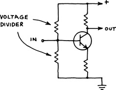
Voltage dividers are used to bias transistors:
They’re also a convenient source of variable voltage:

And they’re useful in voltage sensing circuits. See the comparator circuits in this notebook.
CAPACITORS
Capacitors store electrical energy and block the flow of direct current while passing alternating current. Capacitance is specified in farads. One farad represents a huge capacitance so most capacitors have values of small fractions of a farad:
The value of a capacitor is usually printed on the component. The µF and pF designations may not be present.
Small ones marked 1-1000 are rated in pF; larger ones marked .001-1000 are rated in µF.
Electrolytic capacitors provide high capacity in a small space. Their leads are polarized and must be connected into a circuit in the proper direction.
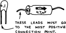
Capacitors have a voltage rating. It’s usually printed under the capacity marking. The voltage rating must be higher than the highest expected voltage (usually the power supply voltage).
Caution: A capacitor can store a charge for a considerable time after power is removed. This charge can be dangerous! A large electrolytic capacitor charged to only 5 or 10 volts can melt the tip of a screwdriver placed across its leads! High voltage capacitors can store a lethal charge! Discharge a capacitor by carefully placing a resistor (1K or more; use Ohm’s law) across its leads. Use only one hand to prevent touching both leads of the capacitor.
Important capacitor applications:
1. Remove power supply spikes. (Place 0.01-0.1 µF across power supply pins of digital ICs. Stops false triggering.)
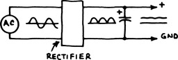
2. Smooth rectified AC voltage into steady DC voltage. (Place 100-10,000 µF across rectifier output.)
3. Block DC signal while passing AC signal.
4. Bypass AC signal around a circuit or to ground.
5. Filter out unwanted portions of a fluctuating signal.
6. Use with resistor to integrate a fluctuating signal:
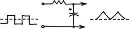
7. Or to differentiate a fluctuating signal:

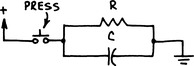
C will quickly charge… then slowly discharge through R.
9. Store a charge to keep a transistor turned off or on.
10. Store a charge to be dumped through a flashtube or LED in a fast and powerful pulse.
Can you substitute capacitors? In most cases changing the value of a capacitor 10% or even 100% will not cause a malfunction, but circuit operation may be affected. In a timing circuit, for example, increasing the value of the timing capacitor will increase the timing period. Changing the capacitors in a filter will change the filter’s frequency response. Be sure to use the proper voltage rating. And don’t worry about the difference between 0.47 and 0.5 µF.

LIGHT EMITTING DIODES
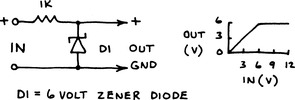
LEDs emit green, yellow, red or infrared when forward biased. A series resistor should be used to limit current to less than the maximum allowed:
![]()
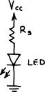
Example: VLED of red LED is 1.7 volts. For a forward current (LED1) of 20 mA at Vcc = 5 volts, R = 165 ohms. Don’t exceed LEDI!!
Infrared LEDs are much more powerful than visible LEDs, but their radiation is totally invisible. Use them for object detectors and communicators.
INTEGRATED CIRCUITS
Since an IC is a complete circuit on a silicon chip, you must observe all operating restrictions. Reversed polarity, excessive supply voltage and sourcing or sinking too much current can destroy an IC. Be sure to pay close attention to the location of the power supply pins! Most ICs are packaged in 8, 14 or 16 pin plastic DIPs (Dual In-line Packages).
A notch or circle is near pin 1:
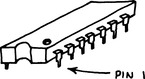
When the IC is right side up, pin 1 is at lower left:
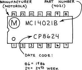
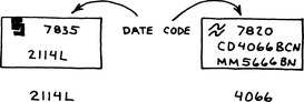
Incidentally, a date code may not be present, but other numbers may be…and the date code is not always below the device number:
Store ICs in a plastic cabinet if you can afford one. Or insert them in rows in a styrofoam tray (the kind used for meat in a grocery store). CAUTION: Never store MOS/CMOS ICs in ordinary non-conductive plastic.