
12
DATA COMMUNICATION AND NETWORKING
Chapter Outline
12.1 INTRODUCTION
The term communication in simple words means sending or receiving information. In ancient times, people used the beating of drums, smoke signals, mirrors reflecting sunlight, homing pigeons, and so on to send messages. Another way of long distance communication was the use of homing pigeons to carry messages. With the advancement in science and technology, various devices were invented for communication. Telegraph was one of the most prevalent ways of data communication in the 19th century. In 1870, Alexander Graham Bell invented the telephone, which revolutionised the way long distance communication used to take place. Voice communication became common after the invention of the telephone. In 1940s and 1950s, a major breakthrough was made in the development of computers and setting up a network of computers for electronic transfer of information or data communication. In fact, the first network was established in 1940, when George Stibitz and Samuel Williams, researchers at Bell Laboratories, developed Complex Number Generator – one of the earliest digital computers, they made it possible for users to operate the computer remotely from teletype machines. They also developed a system to allow users to communicate with the machine even more remotely, through telex machines. The advancement of computer networks and later the Internet acted as a boost for data communication.
Whenever more than one computer is used at the same location, networking them together facilitates exchange of data and information (data communication) between connected computers in a fast and efficient manner. Networking also helps sharing expensive resources like printers, backup tape drives, scanners, Internet connections, and so on. In this chapter, we will discuss how communication system works, various transmission medias and devices, different techniques of data communication, types of computer network, and various network topologies.
12.2 DATA COMMUNICATION
Data communication is the exchange of data between two devices using some form of wired or wireless transmission medium. It includes the transfer of data, the method of transfer and the preservation of the data during the transfer process. To initiate data communication, the communicating devices should be a part of an existing communication system. For data communication to be effective, the following three fundamental characteristics should be considered:
- Delivery: The system must deliver data to the correct or the intended destination.
- Accuracy: The system must deliver data accurately (error free).
- Timeliness: The system must deliver data in a timely manner without enough time lags.
THINGS TO REMEMBER
Communication System
A communication system can be defined as the collection of hardware and software that facilitates intersystem exchange of information between different devices. When we communicate, we are sharing information. This sharing can be local (face to face communication) or it may be remote (communication over distance).
12.2.1 COMPONENTS OF DATA COMMUNICATION
There are five basic components in data communication system.
- Message: It is the information that is to be communicated.
- Sender: The sender is the device that sends the message.
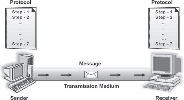
Figure 12.1 Data Communication Components
- Receiver: The receiver is the device that receives the message.
- Medium: The transmission medium is the physical path that communicates the message from sender to receiver.
- Protocol: Protocol refers to a set of rules that coordinates the exchange of information. Both sender and receiver should follow the same protocol to communicate data. Without the protocol, the sender and receiver cannot communicate with each other; just as a person speaking English cannot be understood by a person who speaks only Hindi.
Suppose you want to convey your final marks to your mother. You call her via telephone and inform her about your marks. Here your marks is the message, you are the sender, your mother is the receiver, the telephone line is the medium, and the language in which you are conversing is the protocol.
12.2.2 DATA TRANSMISSION MODE
Data transmission mode refers to the direction of signal flow between two linked devices. There are three types of transmission modes: simplex, half-duplex, and full-duplex.
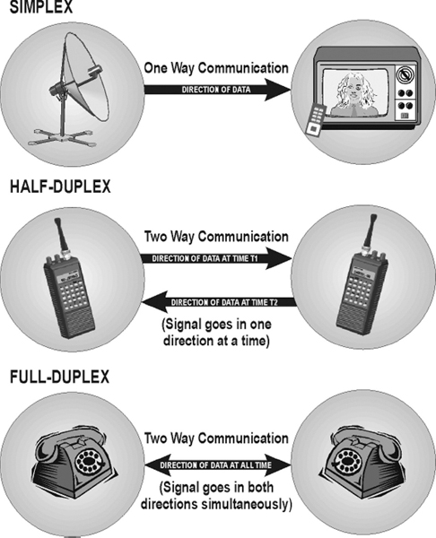
Figure 12.2 Data Transmission Modes
Simplex
Simplex transmission is unidirectional. The information flows in one direction across the circuit, with no capability to support response in the other direction. Only one of the communicating devices transmits information, the other can only receive it. Television transmission can be considered as an example of simplex mode of transmission where the satellite only transmits the data to the television, vice versa is not possible.
Half-duplex
In half-duplex mode, each communicating device can receive and transmit information, but not at the same time. When one device is sending, the other can only receive at that point of time. In half-duplex transmission mode, the entire capacity of the transmission medium is taken over by the device, which is transmitting at that moment. For example, two-way radio was the first to use half-duplex where one party spoke and the other party listened.
Full-duplex
Full-duplex transmission mode, also known as the duplex mode, allows both communicating devices to transmit and receive data simultaneously. A full-duplex mode can be compared to a two-way road with traffic flowing in both directions. A standard voice telephone call is a full-duplex call because both parties can talk at the same time and be heard.
12.2.3 ANALOG AND DIGITAL DATA TRANSMISSION
The major role of the physical medium is to move information from one communicating device to another. However, information to be transmitted should be first transformed into electromagnetic signals. For example, you cannot just write a letter on the piece of paper, insert it into a wire, and transmit it across town. Information over any medium is transmitted by two main methods: analog and digital.
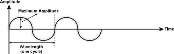
Analog Signals
An analog signal is a continuous waveform that changes smoothly over time. The sine wave is the most fundamental form of an analog signal. Sine waves can be described by three characteristics.
- Amplitude: It is the value of the signal at any point on the wave. The maximum amplitude of a sine wave is the highest value it reaches on the vertical axis. The unit for amplitude depends on the type of the signal. For electrical signals, the unit is normally volts and amperes.
- Frequency: It refers to the number of cycles a signal completes in one second. In other words, frequency means the number of times a signal wave goes up and down in a second and it is measured in Hertz (Hz). For example, if a signal wave completes one cycle in one second, its frequency is one Hz.
- Wavelength: It refers to the distance between successive similar points of a given wave, that is, one cycle of the waveform.
Analog signals are perfect for carrying data such as voice or sound. However, these signals are prone to errors or noise, which are caused from an outside source. Attenuation is another problem with analog signals because the amplitude of the wave naturally changes over distance.
Digital Signals
Digital signal is the data stored in the form of 0s and 1s. When the signal is at a high point, its value is 1 and when it is low, its value is 0. A signal in digital format has precise voltages that are not affected by noise or attenuation as compared to analog signals, which are very prone to noise. Digital signals can be represented by a graph similar to a bar graph. In Figure 12.4, 1 can be encoded as a positive voltage and 0 as zero voltage.
To transmit data over analog phone lines, a modem is required to convert the digital data signals to analog signals. When transmitted over long distances, analog signals require to be amplified, which can possibly distort the value of the data transmitted. When analog data is converted to digital data, it can be transmitted over digital signals faster and without distortion. Digital data is precise, but can never transmit the range of information available, which is possible in case of analog data transmission.
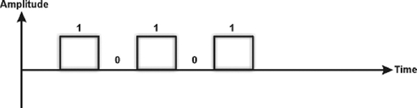
Figure 12.4 Digital Signal
12.2.4 DATA COMMUNICATION MEASUREMENT
The measurement of the quantity of data that can be passed down a communication link in a given time is done in terms of bandwidth. Fundamentally, bandwidth refers to the maximum volume of information that can be transferred over any communication medium. The more the information needed to transmit in a given period, the more the bandwidth required. On digital circuits, bandwidth is measured in bits per second (bps), which refers to the number of binary data bits transmitted per second. A thousand bps is one kilobit per second or Kbps.
In the popular digital context, the level of bandwidth falls into three categories.
- Narrowband: In narrowband, there is a single transmission channel of 64 Kbps or less. With advances in network technology, narrowband has come to be associated with any channel operating at less than 1.544 Mbps.
- Wideband: It is a medium capacity communication channel, which carries data at speeds between 1.544 Mbps to 45 Mbps.
- Broadband: It is a transmission medium, capable of supporting a wide range of frequencies. It can carry multiple signals by dividing the total capacity of the medium into multiple, independent bandwidth channels, where each channel operates only on a specific range of frequencies. The bandwidth capacity in broadband is equal to 45 Mbps. Broadcast television, cable television, microwave, and satellite are examples of broadband technologies. These technologies are capable of carrying a great deal of information in a short amount of time, but are more expensive to use than technologies like the telephone, which require less bandwidth.
12.3 TRANSMISSION MEDIA
Transmission media refers to the physical media through which communication signals (data and information) are transmitted. The information or a signal transmitted from one device to another is through electromagnetic signals. An electromagnetic signal is the combination of electric and magnetic fields, vibrating in conjugation with each other. Electromagnetic signals include power, voice, radio waves, infrared light, visible light, ultraviolet light, X-rays, and gamma rays. All these together constitute an electromagnetic spectrum. These signals can travel through vacuum, air or any other transmission medium. Voice signals are generally transmitted as current over metal cables. Radio frequencies are generally transmitted through air or space. Third type of electromagnetic energy is the visible light, which is currently being used for communication through fibre optic cable. Transmission media can be divided into two broad categories: guided media and unguided media.
12.3.1 GUIDED MEDIA
Guided transmission media use a cabling system that guide the data signals along a specific path. Cable is the medium through which information usually moves from one network device to another. It consists of a cable of various metals like copper, tin or silver. The data signal in guided medium is bound by the cabling system; hence, guided medium is also known as bound medium. There are three basic types of guided media—twisted pair, coaxial cable, and optical fibre.
Twisted Pair
The biggest network in the world, the telephone network, originally used only twisted-pair cabling and still does for most local connections. The name comes from the fact that each individually insulated conductor is part of a pair, making this a balanced medium, and that each pair is twisted together along its length, which helps to further protect it from interference from external sources. Each pair consists of a wire, used for receiving data signal, and a wire used for transmitting data signal. Twisted pairs are used in a short distance communication (less than 100 meters). It comes in two forms, namely, unshielded and shielded with a metal sheath or braid around it. The two are commonly known as Unshielded Twisted Pair (UTP) and Shielded Twisted Pair (STP).
- UTP Cable: It is the most common type of telecommunication medium in use today. It is most suited for both data and voice transmission, hence is commonly used in telephone systems. The cable has four pairs of wires inside the jacket. Each pair is twisted with a different number of twists per inch to help eliminate interference from adjacent pairs and other electrical devices. The tighter the twisting, the higher the supported transmission rate and the greater the cost per foot. Each twisted pair consists of two metal conductors (usually copper) that are insulated separately with their own coloured plastic insulation.
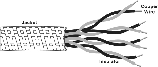
Figure 12.5 Unshielded Twisted Pair Cable
- STP Cable: This cable has a metal foil or braided-mesh covering that covers each pair of insulated conductors. The metal foil is used to prevent infiltration of electromagnetic noise. This shield also helps to eliminate crosstalk, a phenomenon that can be experienced during telephone conversation when one can hear another conversation in the background. A disadvantage of UTP is that it may be susceptible to radio and electrical frequency interference. Shielded twisted pair is suitable for environments with electrical interference; however, the extra shielding can make the cables quite bulky.
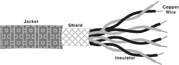
Figure 12.6 Shielded Twisted Pair Cable
Note: All signalling over twisted pair is of the baseband type. Baseband transmission use the entire media bandwidth for a single channel, that is, only one signal can be carried at a time, and all the systems take turns using it.
Coaxial Cable
Coaxial cables have a single central conductor, which is made up of solid wire (usually copper). This conductor is surrounded by an insulator over which a sleeve of metal mesh is woven to block any outside interference. This metal mesh is again shielded by an outer covering of a thick material (usually PVC) known as jacket.
Although coaxial cabling is difficult to install, it is highly resistant to signal interference. It can support greater cable lengths between network devices than twisted pair cable. In addition, as compared to twisted pairs, it also offers higher bandwidth. A coaxial cable is capable of transmitting data at a rate of 10 Mbps. It is more expensive per foot, but cheaper per bytes of data are transferred in a second. Coaxial cable is very robust and is commonly used in cable TV network.
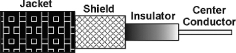
Figure 12.7 Coaxial Cable
Optical Fibre
Twisted pair and coaxial cable transmit data in the form of current. Optical fibre, on the other hand, consists of thin glass fibres that can carry information in the form of visible light. The typical optical fibre consists of a very narrow strand of glass called the core. Around the core is a concentric layer of glass called the cladding. A typical core diameter is 62.5 microns (1 micron = 10-6 metres). Cladding generally has a diameter of 125 microns. The cladding is covered by a protective coating of plastic, known as jacket. Optical fibre has the ability to transmit signals over much longer distances than coaxial and twisted pair. Light signal, unlike electrical signal does heat up the wire and is not susceptible to outside interference. It is extremely hard to tap into, making it desirable from the security point of view. Optical fibre also has the capability to carry information at vastly greater speeds. A single optical fibre can pack hundreds of fibres, where each fibre has the capacity equivalent to that of thousands of twisted pair wires. This capacity broadens communication possibilities to include services such as video conferencing and interactive services. However, fibre optics cable is by far the most expensive per foot. Moreover, it is more difficult to install and modify.
THINGS TO REMEMBER
Optical Fibres
Optical fibres work on the principle that the core refracts the light and the cladding reflects the light. The core refracts the light and guides the light along its path. The cladding reflects any light back into the core and stops it from escaping through the medium. These light pulses, which can be carried over long distances via optical fibre cable, carry information.
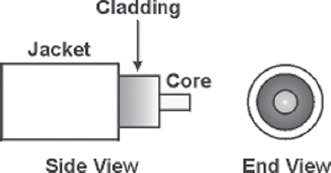
Figure 12.8 Optical Fibre
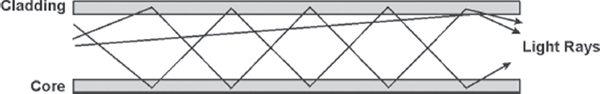
Figure 12.9 Signals Carried over an Optical Fibre
12.3.2 UNGUIDED MEDIA
Unguided transmission media is data signals that flow through the air. They are not guided or bound to a fixed channel to follow. One of the common unguided media of transmission is radio frequency propagation.
Radio Frequency Propagation
In radio frequency propagation, the signal is carried over carrier waves (waves which carry signals over them), which have frequencies in the range of radio frequency spectrum. There are three types of RF (radio frequency) propagation, namely, ground wave, ionospheric, and line of sight.
Ground wave propagation follows the curvature of the earth. They have carrier frequencies of up to 2 MHz. AM radio is an example of ground wave propagation. In ionospheric propagation, the signal wave bounces off the earth's ionosphere layer in the upper atmosphere. It operates in the frequency range of 30–85MHz. As this type of propagation depends on the earth's ionosphere, it changes with the day timings and weather.
Line of sight propagation transmits exactly in the line of sight. The receiving station must be in view of the transmitting station. It is sometimes called space waves or tropospheric propagation. It is limited by the curvature of the earth for ground-based stations (50 km). Examples of line of sight propagation are microwave and satellite.
- Microwave: Microwave transmission is line of sight transmission. The transmit station must be in visible contact with the receive station. This sets a limit on the distance between stations depending on the local geography. Typically, the line of sight due to the earth's curvature is only 50 km to the horizon. Therefore, repeater stations must be placed so the data signal can travel farther than the distance limit.
- Satellite: Satellite transmission is also a kind of line of sight transmission. Satellites are set in geostationary orbits directly over the equator, which rotates in synchronisation to earth, hence look stationary from any point on earth. These geostationary orbits are placed 36,000 km above the earth's surface. The communication is carried through uplinks and downlinks. The uplink transmits the data to the satellite and downlink receives the data from the satellite. Uplinks and downlinks are also called earth stations because they are located on the earth. The area shadowed by the satellite in which the information or data can be transmitted and received is called the footprint.
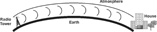
Figure 12.10 Ground Wave Propagation
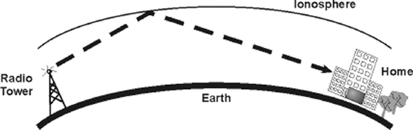
Figure 12.11 Ionospheric Propagation
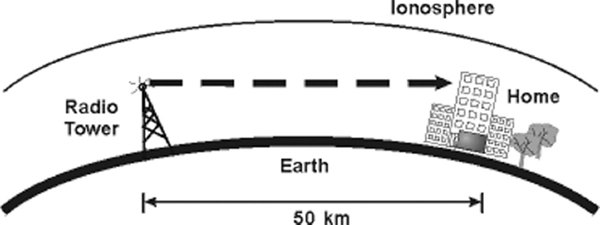
Figure 12.12 Line of Sight Propagation
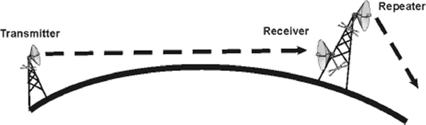
Figure 12.13 Microwave Transmission
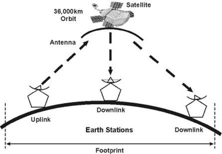
Figure 12.14 Satellite Transmission
12.4 MODULATION
Consider a scenario where a boy standing over the roof of his house has to deliver a paper to the boy standing over the roof of the house in front. Due to the distance between the two roofs, the first boy cannot just hand over the paper to the other. In addition, paper alone cannot travel the distance (if thrown) because it is lightweight. Therefore, the first boy wraps the paper onto a stone and throws it towards the other boy, who catches the stone wrapped in the paper. The boy takes off the paper from the stone, reads the message and discards the stone. In this manner, the first boy is able to deliver a message to the other boy. In the same way, before a signal is transmitted in a wide communication system, the signals (paper) are superimposed on a carrier signal (stone), which propagates by means of an electromagnetic wave. This process is called modulation. Modulation is the addition of information (or the signal) to a signal carrier wave. These carrier waves carry the signals to travel over long distances. Generally, there are three forms of modulation: amplitude, frequency, and phase.
12.4.1 AMPLITUDE MODULATION
In this modulation, the amplitude of a carrier wave is varied in accordance with a characteristic of the modulating signal. The frequency of the carrier remains the same, only the amplitude changes to follow variations in the signal. In simpler words, the two discrete binary digits (0 and 1) are represented by two different amplitudes of the carrier signal. Figure 12.15 depicts how the modulating signal is superimposed over the carrier signal that results in an amplitude-modulated signal.
12.4.2 FREQUENCY MODULATION
In this modulation, the instantaneous frequency of carrier wave is caused to depart from the centre frequency by an amount proportional to the instantaneous value of the modulating signal. In simple words, frequency modulation is the method of impressing modulating signal onto a carrier signal wave by varying its instantaneous frequency rather than its amplitude (see Figure 12.16). Frequency modulation is also known as Frequency Shift Keying (FSK).
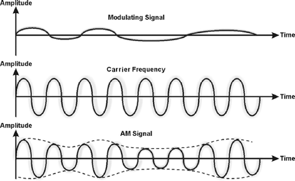
Figure 12.15 Amplitude Modulation
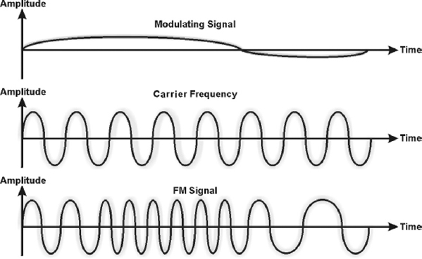
Figure 12.16 Frequency Modulation
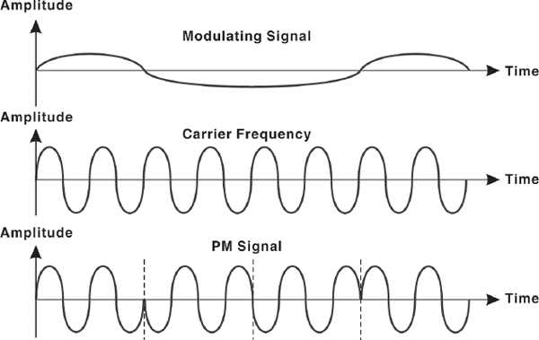
12.4.3 PHASE MODULATION
Phase modulation (PM) is the encoding of information into a carrier wave by variation of its phase in accordance with an input signal. In this modulation technique, the phase of sine wave carrier is modified according to the amplitude of the message to be transmitted (see Figure 12.17). This technique is also called Phase Shift Keying (PSK), which refers to the simple case of phase modulation by a simple signal with only two states.
12.5 MULTIPLEXING
In a network environment, it is common that the transmission capacity of a medium linking two devices is greater than the transmission needs of the connected devices. Hence, the medium can be shared so that it can be used fully. This can be done by multiplexing. Multiplexing is a technique used for sending several signals simultaneously over a common medium. An analogy of multiplexing can be made with a multilane highway. Just as a multilane highway can carry increased volumes of traffic in multiple lanes at higher speeds and at relatively low incremental cost per lane, higher-capacity circuit can carry multiple conversations in multiple channels at relatively low incremental cost per channel.
12.5.1 MULTIPLEXERS
In a multiplexed system, several devices share the capacity of one link called common medium. Figure 12.18 shows the three devices on the left communicating to the devices on the right through the common medium. The communication device that multiplexes (combines) several signals from the devices on the left for transmission over the common medium is called a multiplexer (MUX). At the receiving end, a demultiplexer (DEMUX) completes the communication process by separating multiplexed signals from a transmission line and distributing it to the intended receiver.
Signals are multiplexed using two basic techniques: Frequency Division Multiplexing (FDM) and Time Division Multiplexing (TDM).
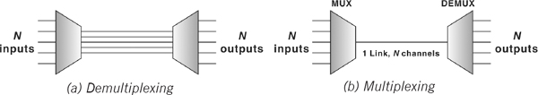
Figure 12.18 A Multiplexed System
Frequency Division Multiplexing
Frequency division multiplexing (FDM) is used when the bandwidth of the transmission medium between the multiplexer and demultiplexer is much greater than the requirements from any one stream being multiplexed. FDM is usually used for broadband analog transmissions. In this technique, signals from each sending device are modulated using carrier waves with different frequencies. These modulated signals are then combined into a single composite signal that is transported over the common medium. Each modulated signal acts as a channel. One of the most common examples of FDM is the transmission of radio stations. Figure 12.19 gives a conceptual view of FDM.
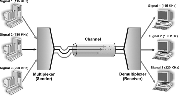
Figure 12.19 Frequency Division Multiplexing
Time Division Multiplexing
Time division multiplexing (TDM) divides the main signal into time-slots, with each time-slot carrying a separate signal. It is used for digital communication and can be applied when the data rate capacity of the transmission medium is greater than the data rate required by the sending and receiving devices. Time division multiplexer allocates each input channel a period of time or time-slot. Figure 12.20 gives a conceptual view of TDM. Each sending device is assigned the transmission path for a predefined time-slot. Three sending signals, Signal 1, Signal 2, and Signal 3, occupy the transmission sequentially. As shown in the figure, time slots A, B, P, Q, etc. follow one after the other to carry signals from the three sources, which upon reaching the demultiplexer, are sent to the intended receiver.
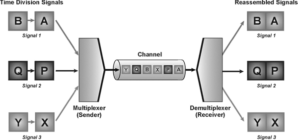
Figure 12.20 Time Division Multiplexing
12.5.2 ASYNCHRONOUS AND SYNCHRONOUS TRANSMISSION
The primary concern while considering the transmission of data from one device to another is to decide whether to send the data one bit at a time (serial mode) or to send a group of bits into a large group (parallel mode). In serial mode, one bit is sent at a given instant; hence, only one communicating channel is needed to transmit data. Since only one communication channel is required, the cost is largely reduced. On the other hand, in parallel mode, multiple bits are sent at any given instance; therefore, more than one channel is needed to transmit data. There is only one way of sending data in parallel mode, but there are two subclasses of serial transmission, namely, asynchronous and synchronous.
Asynchronous Transmission
Asynchronous transmission is so called because the timing of the signal is not important. The information that is received or transmitted follows a predefined pattern. As long as the patterns are followed, the receiving device can retrieve the information without any regard to the timing of the signal sent. However, a synchronising pulse is necessary for the receiver to know when the data is coming and when it is ending. Hence, each byte of information is preceded by a start bit (denoted by 0) and ended by a stop bit (denoted by 1). Therefore, the information in one byte, that is, eight bits becomes ten bits, increasing the overheads. In addition, the transmission of each byte may be followed by a gap of varying duration, which can further help in synchronising the information with the data stream or channel. As soon as receiver detects the stop bit, it ignores any received pulses until it detects the next start bit. The asynchronous transmission is slower than the other forms of transmission but at the same time is cheaper and an attractive choice for low-speed communication.
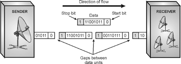
Figure 12.21 Asynchronous Transmission
Synchronous Transmission
Synchronous mode of transmission works on the same media as the asynchronous transmission but the transmitter does not send start and stop bits to the receiver. The receiver's clock is synchronised with the transmitter's clock. In other words, data is transmitted as an unbroken string of 1s and 0s, and the receiver, on the basis of clock timings, separate the string into bytes. Timing becomes very important in synchronous transmission because without start and stop bits, there is no in-built mechanism to help the receiving device accessing the incoming information. The advantage of synchronous transmission is speed. With no extra start and stop bits, overhead is lessened, increasing the speed of transmission. Therefore, synchronous transmission is useful for high-speed application like transfer of large data from one computer to another.
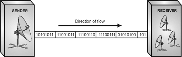
Figure 12.22 Synchronous Transmission
12.6 SWITCHING
Consider a scenario of a small office having four telephone sets used by the four employees for communication. If direct lines were to be used for all the people, 6 duplex lines are required n(n-1)/2 lines, where n is the number of telephone sets. This is called point-to-point connection.
This method, however, is impractical and wasteful when applied to very large networks. The number and length of the links require too much of infrastructure, in addition, majority of these links would remain idle and wasted most of the time. A better solution is switching. On a network, switching means routing traffic by setting up temporary connections between two or more network points. This is done by devices located at different locations on the network, called switches (or exchanges). In a switched network, some switches are directly connected to the communicating devices while others are used for routing or forwarding information.
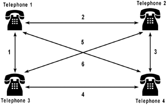
Figure 12.23 Point-to-point Connection
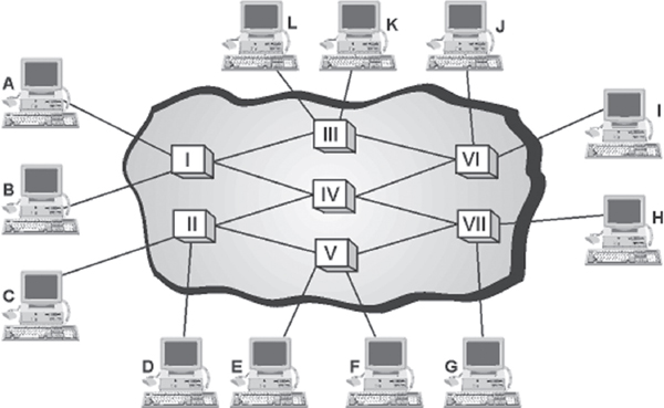
Figure 12.24 depicts a switched network in which communicating devices are labelled A, B, C, and so on and switches are labelled I, II, III, IV, and so on. Each switch is connected either to a communicating device or to any other switch for forwarding information. Notice that multiple switches are used to complete the connection between any two communicating devices at a time, hence saving the extra links required in case of a point-to-point connection.
Switching traditionally employs three methods: circuit switching, packet switching, and message switching. Out of these, only circuit and packet switching are in use nowadays, message switching has been phased out in general communications.
12.6.1 CIRCUIT SWITCHING
When a device wants to communicate with another device, circuit switching technique creates a fixed-bandwidth channel, called a circuit, between the source and the destination. This circuit is reserved exclusively for a particular information flow, and no other flow can use it. Other circuits are isolated from each other, and thus their environment is well controlled.
As illustrated in Figure 12.25, if device A wants to communicate with device D, sets of resources (switches I, II, and III) are allocated which act as a circuit for the communication to take place. The path taken by data between its source and destination is determined by the circuit on which it is flowing, and does not change during the lifetime of the connection. The circuit is terminated when the connection is closed. Therefore, this method is called circuit switching. A common example of a circuit switched network is Public Switched Telephone Network (PSTN).
THINGS TO REMEMBER
Circuit Switching
Circuit switching is plagued by many disadvantages. When there is no flow of data, the capacity of incurring link is wasted. Circuit switching is less suited to data communication, where the data comes in surges with idle gaps between them. It is inflexible as well, that is, once the circuit is established, that circuit is the only path taken by the flow of information whether or not it remains the most efficient and available.
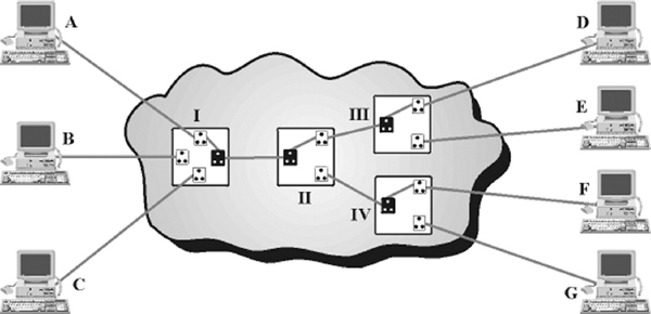
Figure 12.25 Circuit Switching
In circuit switching, data is transmitted with no delay (except for negligible propagation delay). This method is simple and requires no special facilities. Therefore, it is well suited for low speed data transmission.
12.6.2 PACKET SWITCHING
Circuit switching was designed for voice communication. For example, in voice communication such as a telephonic conversation, once a circuit is established it remains busy for the duration of the conversation session. However, circuit switching is marred with many limitations, such as in case of idle time (that is, if no data is communicated), the capacity of the link is wasted. This situation is addressed by packet switching.
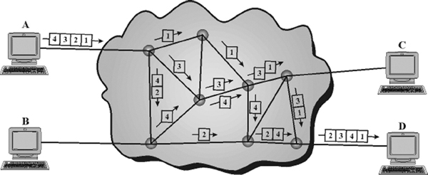
Packet switching introduces the idea of breaking data into packets, which are discrete units of potentially variable length blocks of data. Apart from data, these packets also contain a header with control information like the destination address, priority of the message, and so on. These packets are passed by the source point to its local Packet Switching Exchange (PSE). When the PSE receives a packet, it inspects the destination address contained in the packet. Each PSE contains a navigation directory specifying the outgoing links to be used for each network address. On receipt of each packet, the PSE examines the packet header information and then either removes the header or forwards the packet to another system. If the channel is not free, then the packet is placed in a queue until the channel becomes free. As each packet is received at each transitional PSE along the route, it is forwarded on the appropriate link mixed with other packets. At the destination PSE, the packet is finally passed to its destination. Note that not all packets travelling between the same two points, even those from a single message, will necessarily follow the same route. Therefore, after reaching their destination, each packet is put into order by a Packet Assembler and Disassembler (PAD). Figure 12.26 shows that four packets (1, 2, 3, and 4) once divided on machine A are transmitted via various routes, which arrive on the destination machine D out of order. The destination machine then assembles the arrived packets in order and retrieves the information.
The benefit of packet switching is that since packets are short, the communication links between the nodes are only allocated to transferring a single message for a short period while transmitting each packet. Longer messages require a series of packets to be sent, but do not require the link to be dedicated between the transmission of each packet. This also allows packets belonging to other messages to be sent between the packets of the original message. Hence, packet switching provides a much fairer and efficient sharing of the resources. In addition, if no data is available at the sender at some point during a communication, then no packet is transmitted over the network and no resources are wasted. Due to these characteristics, packet switching is widely used in data networks like the Internet.
12.6.3 MESSAGE SWITCHING
Message switching technique employs the ‘store and forward’ mechanism. In this mechanism, a special device (usually a computer system with large memory storage) in the network receives the message from a communicating device and stores it into its memory. Then it finds a free route and sends the stored information to the intended receiver. In this kind of switching, a message is always delivered to one device where it is stored and then rerouted to its destination.
Message switching is one of the earliest types of switching techniques, which was common in 1960s and 1970s. As the delays in such switching are inherent (time delay in storing and forwarding the message) and a large capacity of data storage is required, this technique has virtually become obsolete.
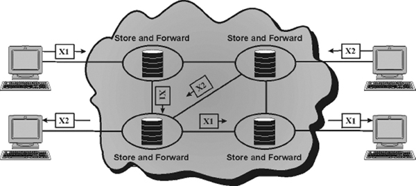
Figure 12.27 Message Switching
12.7 COMPUTER NETWORK
A computer network is a collection of two or more computers, which are connected together to share information and resources. The key word in the definition is ‘sharing’, the main purpose of computer networking. The ability to share information efficiently is what gives computer networking its power and its appeal. Envision a network as a project team. Through the efforts of all involved—the sharing of time, talent, and resources—a goal is accomplished or a project is completed.
Personal computers are powerful tools that can process and manipulate large amounts of data quickly, but they do not allow users to share that data efficiently. Before networks, users needed either to print documents or copy files to a disk for others to edit or use them. If others made changes to the document, there was no easy way to merge the changes. This is known as stand-alone environment. However, when two computers are linked together using a cable that allows them to share data, it is known as networked environment. Observe in Figure 12.28(b), the computers and other devices (like printers) are connected together through a cable. This is called a network and the concept of connected computers sharing resources is called networking. Note that computers in a network are interconnected by telephone lines, coaxial cables, satellite links, radio, and so on.
Technological advances in networking hardware and software have led to greater throughput on all scales and to increasingly tighter integration of networking with all aspects of computing. In tandem with these advances, the idea of networking has entered the common consciousness to an extent that would have been unimaginable a few years ago. This shift in perception has led to an expansion of networking beyond the workplace, which is already beginning to shape developments in networking technology.
Unlike operating system, such as DOS that is designed for single user to control one computer, network operating systems (NOS) is an interconnected system of computing devices that provide shared and economical access to computer services. Thus, network operating systems coordinate the activities of multiple computers across a network. NOS are broadly divided into two types namely, client/server and peer-to-peer networks.
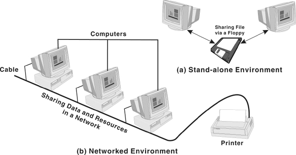
Figure 12.28 Stand-alone and Networked Environments
Client/server Network
In this network, each computer is either a client or a server. To complete a particular task, there exists a centralised host computer known as server and a user's individual workstation known as client. In simple words client requests a service from the server and the server responds by providing that service. Note that a client/server network centralises functions and applications in one or more dedicated file servers.
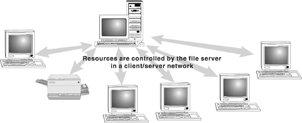
Figure 12.29 Client/server Network
The servers provide access to resources, while the clients have access to the resources available on the servers. A typical example of client-server is sending an email, where the email is first transmitted to the source server. After this, the email is transmitted to the destination server. Lastly, the destination server sends the email to the client at the other end. Other examples of client/server networks include a computer running DOS, requesting a file that is stored on a NetWare file server and a Windows application running on a user's PC that requests data from a computer running Lotus Notes.
Generally, the server software runs on a computer, dedicated solely for hosting that software and supporting its services. On the other hand, client software runs on common personal computers or workstations. In a client/server relationship, both the client and server carry out some of the data processing on their ends. In the example, discussed earlier (e-mail) servers are responsible for transmitting the message, while client is responsible for sending and receiving the message.
Peer-to-peer Network
A peer-to-peer (or P2P) computer network does not rely on dedicated servers for communication instead it uses direct connections between clients (peers). A pure peer-to-peer network does not have the notion of clients or servers, but only equal peer nodes that simultaneously function as both “clients” and “servers” to the other nodes on the network. That is, every node is able to initiate or complete any supported transaction (file transfer) with the other connected node.
The upper limit of the number of nodes that can function as both clients and servers on a peer- to-peer network is between 10 and 25. If there are more nodes, then a peer-to-peer machine can be used as a dedicated server with additional high-performance hardware. Note that the peer nodes involved in the network may differ in local configuration, processing speed, network bandwidth, and storage quantity.
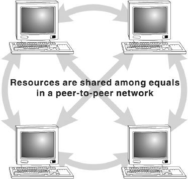
Figure 12.30 Peer-to-peer Networks
Peer-to-peer networks have been designed primarily for small to medium local area networks. These networks have gained widespread popularity on the Internet. Many file sharing services such as Morpheus and Kaaza are used extensively to find files (sound, images, videos) on the network. However, most of these file-sharing services actually integrate both peer-to-peer and client/server networking design. Therefore, these file-sharing applications are technically known as hybrid networks.
Note: P2P is often confused with Point-to-Point, as used in telecommunications.
Generations in Peer-to-peer Networks
Sometimes peer-to-peer file-sharing networks are classified according to their ‘generations’. These generations are based on the popular Internet based file-sharing networks, which are listed below:
- First Generation: This generation had a centralised file list, like Napster. In the United States of America, judiciary ruled that whoever controlled this centralised file list was responsible for any infringement of copyright, or any other illegal activities, which might occur while transferring files.
- Second Generation: This generation had decentralised file lists, such as Gnutella and FastTrack. This was a necessary step for network creators, as a central authority (creators) will be held liable for copyright infringement.
- Third Generation: This generation is an improvement upon previous generations. These networks have in-built features such as efficiency, reliability, and anonymity. Examples of anonymous networks are Freenet, I2P, GNUnet, Entropy. These networks allow only the known users (friends) to connect to your computer. After connecting, each node can forward requests and files anonymously between its own “friends” nodes.
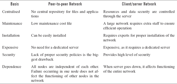
Difference between Peer-to-peer and Client/server Network
Both peer-to-peer and client/server networks have associated advantages and disadvantages. These advantages and disadvantages form a part of distinction between the two. These differences are listed in Table 12.1.
Table 12.1 Difference between Peer-to peer Network and Client/server Network
12.7.1 TYPES OF COMPUTER NETWORKS
A network can be as few as several personal computers on a small network or as large as the Internet, a worldwide network of computers. Today, when talking about networks, we are generally referring to three primary categories: Local Area Network (LAN), Metropolitan Area Network (MAN), and Wide Area Network (WAN). These categories are defined depending upon various factors like the size of the network, the distance it covers, and the type of link used in interconnection.
Local Area Network (LAN)
A LAN is a computer network that covers only a small geographical area (usually within a square mile or less), such as an office, home or building. In a local area network, computers connected have a network operating system installed onto them. One computer is designated as the file server, which stores all the software that controls the network. It also stores the software that can be shared by the computers attached to the network. Other computers connected to the file server are called workstations. The workstations can be less powerful than the file server, and they may have additional software on their hard drives. On most LANs, cables are used to connect the computers. Generally, LAN offers a bandwidth of 10 to 100 Mbps.
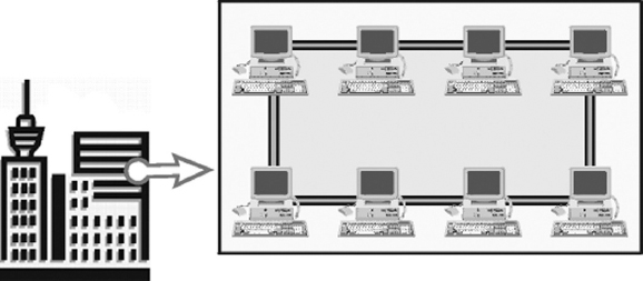
Figure 12.31 Local Area Network
Metropolitan Area Network (MAN)
A MAN, or Metropolitan Area Network, is a network of computers spread over a ‘metropolitan’ area such as a city and its suburbs. As the name suggests, this sort of network is usually reserved for metropolitan areas where the city bridges its local area networks with a series of backbones, making one large network for the entire city. It may be a single network such as a cable television network or it may be a means of connecting a number of LANs. Note that MAN may be operated by one organisation (a corporate with several offices in one city), or be shared resources used by several organisations in the same city.
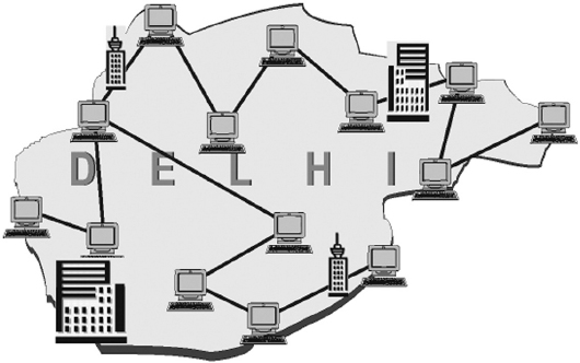
Figure 12.32 Metropolitan Area Network
Wide Area Network (WAN)
A WAN, or Wide Area Network, is a system of interconnecting many computers over a large geographical area such as cities, states, countries or even the whole world. These kinds of networks use telephone lines, satellite links, and other long-range communications technologies to connect. Such networks are designed to serve an area of hundreds or thousands of miles such as public and private packet switching networks and national telephone networks. For example, a company with offices in New Delhi, Chennai, and Mumbai may connect the LANs for each of those locations to each other through a WAN. Although a WAN may be owned or rented by private business, it is usually a public network designed to connect small and intermediate sized networks together. The largest WAN in existence is the Internet.
WAN offers many advantages to business organisations. Some of them are as follows:
- It offers flexibility of location because not all the people using the same data have to work at the same site.
- Communication between branch offices can be improved using e-mail and file sharing.
- It facilitates a centralised company wide data backup system.
- Companies located in a number of small, interrelated offices can store files centrally and access each other's information.
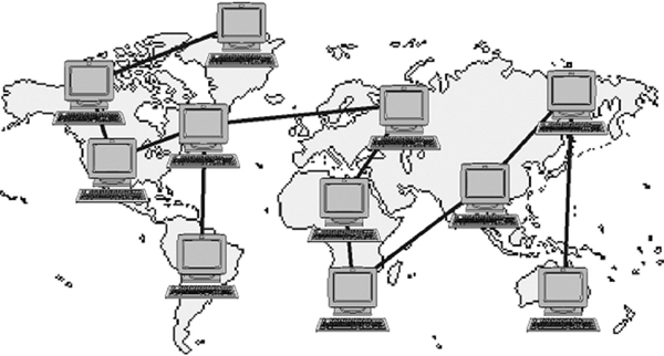
Figure 12.33 Wide Area Network
12.8 NETWORK TOPOLOGIES
The term topology refers to the way a network is laid out, either physically or logically. A topology can be considered as the network's shape. It is the geometric representation of the relationship of all the links. There are five basic topologies: Bus, Ring, Star, Tree, and Mesh.
12.8.1 BUS TOPOLOGY
Bus topology uses a common bus or backbone (a single cable) to connect all devices with terminators at both ends. The backbone acts as a shared communication medium and each node (file server, workstations, and peripherals) is attached to it with an interface connector. Whenever a message is to be transmitted on the network, it is passed back and forth along the cable, past the stations (computers) and between the two terminators, from one end of the network to the other. As the message passes each station, the station checks the message's destination address. If the address in the message matches the station's address, the station receives the message. If the addresses do not match, the bus carries the message to the next station, and so on. Figure 12.34 illustrates how devices such as file servers, workstations, and printers are connected to the linear cable or the backbone.
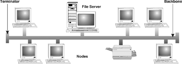
Figure 12.34 Bus Topology
Advantages of Bus Topology
The advantages of bus topology are:
- Connecting a computer or peripheral to a linear bus is easy.
- This topology requires least amount of cabling to connect the computers and, therefore, less expensive than other cabling arrangement.
- It is easy to extend a bus since two cables can be joined into one longer cable with a connector.
Disadvantages of Bus Topology
The disadvantages of bus topology are:
- Entire network shuts down if there is a failure in the backbone.
- Heavy traffic can slow down a bus because computers on such networks do not coordinate with each other to reserve time to transmit.
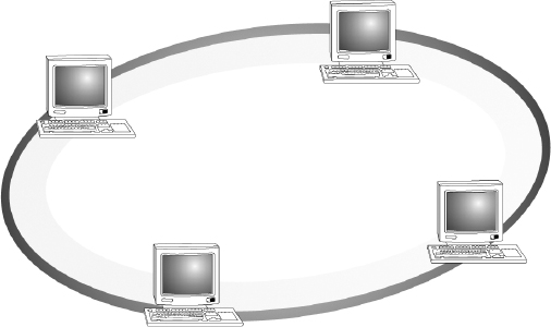
12.8.2 RING TOPOLOGY
In ring topology, computers are placed on a circle of cable without any terminated ends since there are no unconnected ends. Every node has exactly two neighbours for communication purposes. All messages travel through a ring in the same direction (clockwise or counter-clockwise) until it reaches its destination. Each node in the ring incorporates a repeater. When a node receives a signal intended for another device, its repeater regenerates the bits and passes them along the wire.
Advantages of Ring Topology
The advantages of ring topology are:
- Ring topology is easy to install and reconfigure.
- Every computer is given equal access to the ring. Hence, no single computer can monopolise the network.
Disadvantages of Ring Topology
The disadvantages of ring topology are:
- Failure in any cable or node breaks the loop and can take down the entire network.
- Maximum ring length and number of nodes are limited.
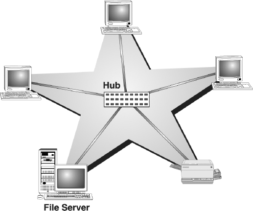
12.8.3 STAR TOPOLOGY
In star topology, devices are not directly linked to each other but they are connected via a centralised network component known as hub or concentrator. The hub acts as a central controller and if a node wants to send data to another node, it boosts up the message and sends the message to the intended node. This topology commonly uses twisted pair cable; however, coaxial cable or fibre optic cable can also be used.
Advantages of Star Topology
The advantages of star topology are:
- Star topology is easy to install and wire.
- The network is not disrupted even if a node fails or is removed from the network.
- Fault detection and removal of faulty parts is easier in star topology.
Disadvantages of Star Topology
The disadvantages of star topology are:
- It requires a longer length of cable.
- If the hub fails, nodes attached to it are disabled.
- The cost of the hub makes the network expensive as compared to bus and ring topology.
12.8.4 TREE TOPOLOGY
A tree topology combines characteristics of linear bus and star topologies. It consists of groups of star-configured workstations connected to a bus backbone cable. Not every node plugs directly to the central hub. The majority of nodes connect to a secondary hub that, in turn, is connected to the central hub. Each secondary hub in this topology functions as the originating point of a branch to which other nodes connect.
Advantages of Tree Topology
The advantages of tree topology are:
- The distance to which a signal can travel increases as the signal passes through a chain of hubs.
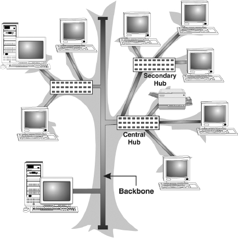
Figure 12.37 Tree Topology
- Tree topology allows isolating and prioritising communications from different nodes.
- Tree topology allows for easy expansion of an existing network, which enables organisations to configure a network to meet their needs.
Disadvantages of Tree Topology
The disadvantages of tree topology are:
- If the backbone line breaks, the entire segment goes down.
- It is more difficult to configure and wire than other topologies.
12.8.5 MESH TOPOLOGY
In a mesh topology, every node has a dedicated point-to-point link to every other node. Messages sent on a mesh network can take any of several possible paths from source to destination. A fully connected mesh network has n(n-1)/2 physical links to link n devices. For example, if an organisation has 5 nodes and wants to implement a mesh topology, 5(5-1)/2, that is, 10 links are required. In addition, to accommodate that many links, every device on the network must have n-1 communication (input/output) ports.
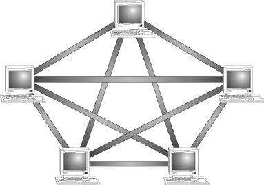
Figure 12.38 Mesh Topology
Advantages of Mesh Topology
The advantages of mesh topology are:
- The use of large number of links eliminates network congestion.
- If one link becomes unusable, it does not disable the entire system.
Disadvantages of Mesh Topology
The disadvantages of mesh topology are:
- The amount of required cabling is very large.
- As every node is connected to the other, installation and reconfiguration is very difficult.
- The amount of hardware required in this type of topology can make it expensive to implement.
12.9 COMMUNICATION PROTOCOL
Imagine yourself standing near a traffic crossing. You can notice that for smooth movement of the traffic, a functioning traffic light is essential. The red signal sends a message to stop, a yellow signal to wait, and a green signal to cross. This set of rules, which tells a driver when to move and when to stop, are traffic protocols. Similarly, computers adhere to certain protocols that define the manner in which communication takes place. A computer protocol is a set of rules that coordinates the exchange of information. If one computer is sending information to another and they both follow the same protocol, the message gets through; regardless of what types of machines they are and on what operating systems they are running. As long as machines have software that can manage the protocol, communication is possible.
12.9.1 THE OSI MODEL
Open Systems Interconnection (OSI) is a standard reference model for communication between two end users in a network. In 1983, International Organisation for Standardisation (ISO) published a document called ‘The Basic Reference Model for Open Systems Interconnection’, which visualises network protocols as a seven-layered model. The model lays a framework for the design of network systems that allow for communication across all types of computer systems. It consists of seven separate but related layers, namely, Physical, Data Link, Network, Transport, Session, Presentation, and Application.
A layer in the OSI model communicates with two other OSI layers, the layer directly above it and the layer directly below it. For example, the data link layer in System X communicates with the network layer and the physical layer. When a message is sent from one machine to another, it travels down the layers on one machine and then up the layers on the other machine. This route is illustrated in Figure 12.39. As the message travels down the first stack, each layer (except the physical layer) adds header information to it. These headers contain control information that are read and processed by the corresponding layer on the receiving stack. At the receiving stack, the process happens in reverse. As the message travels up the other machine, each layer strips off the header added by its peer layer.
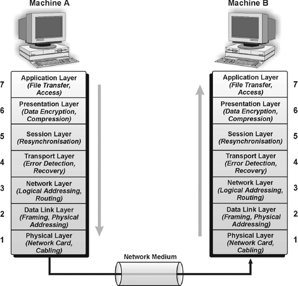
Figure 12.39 Message Transfer in Layered Architecture
Physical Layer
The physical layer defines the physical and electrical characteristics of the network. This layer acts as a conduit between computer's networking hardware and its networking software. It handles the transfer of bits (0s and 1s) from one computer to another. This is where the bits are actually converted into electrical signals that travel across the physical circuit. Physical layer communication media include various types of copper or fibre optic cable, as well as many different wireless solutions.
Data Link Layer
The function of the data link layer is to transform the data into a line that is free of transmission errors and is responsible for its delivery. The data link layer divides the stream of bits from the network layer into manageable form known as frames. These data frames are then transmitted sequentially to the receiver. On the receiver end, data link layer detects and corrects any errors in the transmitted data, which it gets from the physical layer.
Network Layer
The network layer is responsible for transporting traffic between devices that are not locally attached. For example, a router (a network layer device) provides the routing services in a network. When a packet is received on a router interface, the destination IP address is checked. If the packet is not destined for the router, then the router will look up the destination network address in the routing table. Once an exit interface is chosen, the packet will be sent to the interface to be framed and sent out on the local network. If the entry for the destination network is not found in the routing table, the router drops the packet.
Transport Layer
The basic function of the transport layer is to handle error recognition and recovery of the data packets. This layer establishes, maintains, and terminates communications between the sender and the receiver. At the receiving end, transport layer rebuilds packets into the original message, and to ensure that the packets arrived correctly, the receiving transport layer sends receipt acknowledgments.
Session Layer
The session layer comes into play primarily at the beginning and end of a transmission. At the beginning of the transmission, it makes known its intent to transmit. At the end of the transmission, the session layer determines if the transmission was successful. This layer also manages errors that occur in the upper layers, such as a shortage of memory or disk space necessary to complete an operation, or printer errors.
Presentation Layer
The function of presentation layer is to ensure that information sent from the application layer of one system would be readable by the application layer of another system. This is where application data is packed or unpacked, ready for use by the running application. This layer also manages security issues by providing services such as data encryption and compresses data so that fewer bits need to be transferred on the network.
Application Layer
The application layer is the entrance point that programs use to access the OSI model and utilise network resources. This layer represents the services that directly support applications. This OSI layer is closest to the end user. Application layer includes network software that directly serves the user, providing such things as the user interface and application features such as electronic mail, USENET newsreaders, etc.
12.10 NETWORK DEVICES
Networks are becoming more complicated and more pervasive everyday. Terms like switch, router, gateway, and hub have become part of our everyday language, yet many people do not fully understand the differences between these devices or how to choose the right one for their network. These devices interconnect individual computers and ensure that they communicate efficiently. This section provides some background information on how each device works and gives some guidance in picking the right solution.
Network Interface Card (NIC)
Network interface card (NIC) is the first contact between a machine and the network. It connects clients, servers, and peripherals to the network through a port. Most network interfaces come as small circuit board that can be inserted onto one of the computer motherboard's slots. Alternatively, modern computers sometimes include the network interface as part of their main circuit boards (motherboards). Each network interface is associated with a unique address called its Media Access Control (MAC) address. The MAC address helps in sending information to its intended destination.
Network interface cards are a major factor in determining the speed and performance of a network. It is a good idea to use the fastest network card available for the type of workstation one is using.
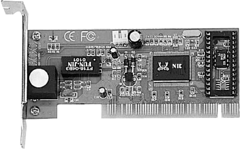
Figure 12.40 Network Interface Card
Repeater
A repeater is the most basic device on a network. Signals that carry information within a network can travel a fixed distance before attenuation endangers the integrity of the data. A repeater installed on the link receives signal, regenerates it, and sends the refreshed copy back to the link. Doing this means that the new signal is clean, free from any background noise introduced while travelling down the wire. In Figure 12.41, two sections in a network are connected by the repeater.
Repeaters are most commonly used to extend a network cable. All network cable standards have maximum cable length specification. If the distance between two network devices is longer than this specification, a repeater is needed to regenerate the signal. Without the repeater, the signal will be too weak for the computers on each end to reliably understand. A good example of the use of repeaters would be in a LAN using a star topology with unshielded twisted pair cabling. The length limit for unshielded twisted pair cable is 100 metres. The repeater amplifies all the signals that pass through it allowing for the total length of cable on the network to exceed the 100 metres limit. Nonetheless, repeaters have no intelligence built-in and do not look at the contents of the packet as they regenerate the signal. Thus, there is no processing overhead in sending a packet through a repeater. This also means that a repeater will repeat any errors in the original signal.
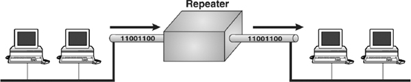
Figure 12.41 Repeater
Hub
A hub is a small box that connects individual devices on a network so that they can communicate with one another. The hub operates by gathering the signals from individual network devices, optionally amplifying the signals, and then sending them onto all other connected devices. Amplification of the signal ensures that devices on the network receive reliable information. A hub can be thought of as the centre of a bicycle wheel, where the spokes (individual computers) meet.
Nowadays, the terms repeater and hub are used synonymously, but they are actually not the same. Although at its very basic level, a hub can be thought of as a multi-port repeater. Typically, hubs have anywhere from 4 to over 400 ports. When a signal is received on one port of the hub it is regenerated out to all the other ports. It is most commonly used to connect multiple machines to the same LAN. Administrators connect a computer to each port on the hub, leaving one port free to connect to another hub or to a higher-level device like a bridge or router.
Since a hub is a multi-port repeater, it is bound by the same limitations. A single LAN segment can only have a certain number of hubs between any two devices before the time it takes a packet to travel from one to the other is too long. Moreover, there is no intelligence in a hub and thus like a repeater no processing overhead in sending information through the hub.
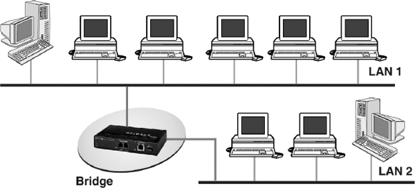
Bridge
A bridge is a device that allows division of a large network into two smaller, more efficient networks. It monitors the information traffic on both sides of the network so that it can pass packets of information to the correct location. Most bridges can ‘listen’ to the network and automatically figure out the address of each computer on both sides of the bridge. It examines each packet as it enters though one of the ports. A bridge first looks at the MAC address of the sender and creates a mapping between the port and the sender's MAC address. It then looks at the address of the recipient, comparing the MAC address to the list of all learned MAC addresses. If the address is in the list, the bridge looks up the port number and forwards the packet out the only the port where it thinks the recipient is connected. If the recipient's MAC address is not in the list, the bridge then does a flood; it sends the signal out all ports except for the one where it was received. As a result, a bridge reduces the amount of traffic on a LAN by dividing it into two segments. It inspects incoming traffic and decides whether to forward or discard it.
One might compare a bridge to a traffic cop at a busy intersection during rush hour. It keeps information flowing on both sides of the network, but it does not allow unnecessary traffic through. Bridges can be used to connect different types of cabling, or physical topologies. They must, however, be used between networks with the same protocol.
Since a bridge examines the packet to record the sender and lookup the recipient, there is overhead in sending a packet through a bridge. On a modern bridge, this overhead is miniscule and should not affect network performance.
Switch
A switch is a multi-port bridge. It connects individual devices on a network so that they can communicate with one another. The behaviour of a switch is the same as a bridge. It is capable of inspecting the data packets as they are received, determining the source and destination device of that packet, and forwarding that packet appropriately. The difference is that most switches implement these functions in hardware using a dedicated processor. This makes them much faster than traditional software based bridges.
Router
A router is an essential network device for interconnecting two or more networks. Router's sole aim is to trace the best route for information to travel. As network traffic changes during the day, routers can redirect information to take less congested routes. A router creates and/or maintains a table, called a routing table that stores the best routes to certain network destinations. While bridges know the addresses of all computers on each side of the network, routers know the addresses of computers, bridges, and other routers on the network. Routers can even ‘listen’ to the entire network to determine which sections are the busiest – they can then redirect data around those sections until they clear up.
Routers are generally expensive and difficult to configure and maintain. They are critical components of a network, if they fail, the network services will be significantly impaired. Most routers operate by examining incoming or outgoing signals for information at the network layer. In addition, they can permit or deny network communications with a particular network.
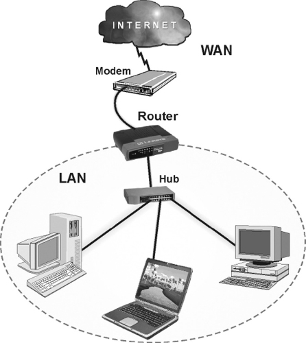
Figure 12.43 Router
Gateway
A gateway is an internetworking device, which joins two different network protocols together. It is also known as protocol converter. A gateway accepts the packet formatted for one protocol and converts the formatted packet into another protocol. It can be implemented completely in software, hardware, or as a combination of both. For example, a gateway can receive e-mail message in one format and convert them into another format. One can connect systems with different protocols, languages, and architecture using a gateway.
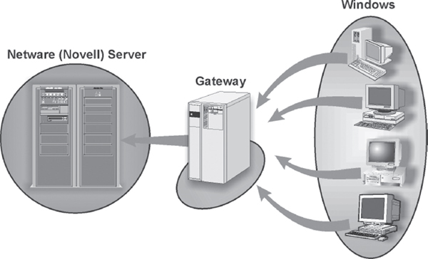
Figure 12.44 Gateway
LET US SUMMARISE
- Data communication is the exchange of data between two devices via some form of wired or wireless transmission medium. There are five basic components in data communication: message, sender, receiver, medium, and protocol.
- The direction of signal flow between two communicating devices is defined by the data transmission modes. There are three types of transmission modes: simplex (unidirectional data flow), half-duplex (bi-directional data flow, but one at a time), and full-duplex (simultaneous bi-directional data flow).
- Bandwidth refers to the maximum volume of information that can be transferred over any communication medium. The greater the amount of information needed to transmit in a given period, the more the bandwidth required.
- The physical or wireless medium through which two communicating devices communicate is known as transmission media. The wired (physical) transmission mediums are known as guided mediums and the wireless transmission mediums are known as unguided mediums.
- There are three basic types of guided media: twisted pair, coaxial cable, and optical fibre. Unguided transmission media is data signals that flow through the air. One of the common unguided media of transmission is radio frequency propagation (microwave and satellite).
- Information over any medium is transmitted by two main methods called analog and digital. An analog signal is a continuous waveform that changes smoothly over time. Digital data refers to the data stored in the form of 0s and 1s.
- Modulation refers to the process of impressing information on a carrier wave by changing some of the wave's characteristics (such as amplitude, frequency or phase) so that it is more suitable for transmission over the medium between transmitter and receiver. Generally, there are three forms of modulation: amplitude, frequency, and phase.
- Multiplexing refers to the process of transmitting more than one signal over a single link, route or channel. There are two basic multiplexing techniques: frequency-division multiplexing (FDM) and time-division multiplexing (TDM).
- Asynchronous transmission refers to the data transmission of one character at a time, with intervals of varying lengths between transmittals, and with start bits at the beginning and stop bits at the end of each character, to control the transmission.
- Synchronous transmission is a method of communication in which data is sent in blocks, without the need for start and stop bits between each byte. Synchronisation is achieved by sending a clock signal along with the data.
- Switching refers to routing traffic by setting up temporary connections between two or more network points. A temporary connection is achieved by devices located at different locations on the network, called switches. There are three methods of switching: circuit switching, packet switching, and message switching.
- Circuit switching is a type of communication in which a dedicated channel (or circuit) is established between two devices for the duration of transmission.
- Packet switching refers to the data transmission method whereby data is transmitted in packets. Each packet contains addresses for the machine sending it and the machine expected to receive it. At the destination, the packets are reassembled into the original message.
- In message switching, store and forward system is used where each message contains a destination address. It is passed from source to destination through intermediate nodes. At each transfer point in the connection, incoming data is stored in its entirety, and then forwarded to the next point. This process continues until the data reaches its destination.
- A computer network is a collection of two or more computers, which are connected together to share information and resources. A network can be classified into three categories: Local Area Network (LAN), Metropolitan Area Network (MAN), and Wide Area Network (WAN).
- Local area network spans only a small geographical area such as an office, home, or building.
- Metropolitan area network is a network of computers spread over a metropolitan area such as city and its suburbs.
- Wide area network is a system of interconnecting computers over a large geographical area such as cities, states, countries, or even the world.
- Topology refers to the way a network is laid out, either physically or logically. It is the geometric representation of the relationship of all the links. There are five basic topologies: bus, ring, star, tree, and mesh.
- Bus topology network uses a common backbone (a single cable) to connect all devices with terminators at both the ends.
- In ring topology, every node has exactly two neighbours connected to form a ring for communication purposes.
- In star topology, devices are not directly linked to each other but are connected through a hub forming the shape of a star.
- Tree topology consists of groups of star-configured workstations connected to a bus backbone cable.
- In mesh topology, every node has a dedicated point-to-point link to every other node.
- Open systems interconnection (OSI) is a standard reference model for communication between two end users in a network. It consists of seven separate but related layers, namely, physical, data link, network, transport, session, presentation, and application.
- To communicate over a network, a particular set of network devices such as network interface card (NIC), repeater, hub, bridge, switch, router, and gateway are used. These devices interconnect individual computers and ensure that they communicate efficiently.
EXERCISES
Fill in the Blanks
- The sharing of information, which includes transfer and preservation of data, is called ____________
- The three types of data transmission modes are ____________, ____________, and ____________
- The maximum capacity of a channel to carry data is known as ____________
- In ____________ modulation, the amplitude of a carrier wave is varied in accordance with a characteristic of the modulating signal.
- The communication technique, which combines several signals from different devices and transmits over a common medium, is called ____________
- The switching technique where messages are stored and then forwarded to the nearby communicating device is ____________
- A network spread around Los Angeles and its suburbs can be termed as ____________ network.
- A tree topology combines characteristics of ____________ and ____________ topologies.
- The device, which joins two network protocols together, is ____________
- The device, fitted onto the computer's motherboard, which enables computer to communicate over the network, is ____________
Multiple Choice Questions
- The transmission mode which allow both communicating devices to transmit and receive data simultaneously is:
- (a) Simplex
- (b) Full-duplex
- (c) Half-duplex
- (d) None of the above
- Which media does not come under the guided media?
- (a) Optical fibres
- (b) Coaxial cable
- (c) Microwave
- (d) Twisted Pair
- LAN stands for:
- (a) Long area network
- (b) Local area network
- (c) Local audible network
- (d) Limited area network
- A public switched telephone network (PSTN) uses……………………. switching technique.
- (a) Packet
- (b) Message
- (c) Circuit
- (d) None of the above
- The network topology in which devices are not linked to each other and where hub acts as a central controller is:
- (a) Mesh topology
- (b) Star topology
- (c) Ring topology
- (d) Tree topology
- In a ring topology each:
- (a) Terminal is connected to two others, via a communications channel, forming a closed loop.
- (b) Device is connected to a control unit; communication between one device and another must go through the central unit.
- (c) Devices connected to a single common communication device.
- (d) Both (a) and (c).
- The internetworking device that connects two networks together and whose sole aim is to trace the best possible route in the given network for transmitting the information is:
- (a) Hub
- (b) Gateway
- (c) Switch
- (d) Router
- Which of the following cables support the highest bandwidth and faster transmission rate?
- (a) Twisted pair cable
- (b) Coaxial cable
- (c) UTP cable
- (d) Fibre optic cable
- A computer network which provides long distance transmission of data, images, and sound over a large distance is:
- (a) MAN
- (b) WAN
- (c) LAN
- (d) VAN
- Identify the odd term out:
- (a) Router
- (b) PC
- (c) Switch
- (d) NIC
State True or False
- LANs operate within a wide area network.
- A telephone line can only send analog waves.
- In a bus topology, the communications channel consists of only one path for a message to travel to the server.
- Twisted-pair cable uses unguided media for data communication.
- Hub is also called as protocol converter.
- Phase modulation is the encoding of information into a carrier wave by variation of its phase in accordance with an input signal.
- Coaxial cable can be easily tapped.
- Mesh topology involves minimum cabling.
- Optical fibre use copper wires for data transmission.
- In full-duplex communication, both parties can communicate at the same time.
Descriptive Questions
- Write down the advantages and disadvantages of optical fibre.
- Differentiate:
- (a) Time-division multiplexing and frequency-division multiplexing
- (b) Guided and unguided media
- (c) Asynchronous and synchronous transmission
- What is modulation? List its types.
- Explain any three guided and unguided data transmission media.
- What do you mean by computer network? Explain various types of computer networks.
- Explain three basic switching techniques used in the computer network.
- With the help of a diagram, explain various network topologies present in the computer networks.
- Describe the following networking devices:
- (a) Router
- (b) Hub
- (c) Gateway
- (d) Bridge
ANSWERS
Fill in the Blanks
- Data communication
- Simplex, half-duplex, full-duplex
- Bandwidth
- Amplitude modulation
- Multiplexing
- Message switching
- Metropolitan
- Linear bus, Star
- Gateway
- Network interface card (NIC)
Multiple Choice Questions
- (b)
- (c)
- (b)
- (c)
- (b)
- (d)
- (d)
- (d)
- (b)
- (b)
State True or False
- False
- True
- True
- False
- False
- True
- True
- False
- False
- True