
Chapter 32. Real-Time Speed-Limit-Sign Recognition on an Embedded System Using a GPU
Pinar Muyan-Özçelik, Vladimir Glavtchev, Jeffrey M. Ota and John D. Owens
We address the challenging problem of detecting and classifying speed-limit signs in a real-time video stream using an embedded, low-end GPU. We implement three pipelines to address this problem. The first is a detection-only feature-based method that finds objects with radial symmetry (suitable for circular EU-speed-limit signs). In this implementation, we leverage the graphics part of the GPU pipeline to perform the radial-symmetry voting step. The second is a template-based method that searches for image templates in the frequency domain using Fast Fourier Transform (FFT) correlations, suitable for both EU and US speed-limit signs. This method performs recognition (both detection and classification); it incorporates contrast-enhancement, composite filters, frequency-domain detection and classification, and temporal integration to aggregate results over many frames in its implementation. The third is the classic GPU-based SIFT approach that provides a basis for evaluation of recognition results of the template-based approach. We show 88% detection accuracy using the feature-based pipeline on an embedded system (Intel Atom CPU + NVIDIA GeForce 9200 M GS GPU) running at 33 fps. In addition, we show 90% recognition accuracy using the template-based pipeline on an Intel Core2 Duo P8600 2.4 GHz CPU and an NVIDIA GeForce 9600 M GT GPU (a low-end GPU that can be used in an embedded automotive system) running at 18 fps, superior in both accuracy and frame rate to the SIFT-based approach.
32.1. Introduction
Graphics processing units (GPUs) have been increasingly used for applications beyond traditional graphics that are well suited for their capabilities
[11]
. One of these fields is automotive computing. Today's cars provide many features with significant compute requirements and upcoming automotive tasks need even more compute. GPUs are a good fit for performing most of these applications. One group of the automotive tasks well suited for GPU's data-parallel architecture are computer vision-related applications, such as speed-limit-sign recognition.
In this chapter, we present different GPU-based techniques for performing real-time speed-limit-sign recognition on a resource-constrained system with a low-end GPU that can be embedded in a car. The input to our system is a video sequence of EU or US roads taken from a moving vehicle. We process this video in real time to detect and classify speed-limit signs as depicted in
Figure 32.1
.
The main challenge of our study is achieving real-time performance while adhering to the resource constraints imposed by an embedded system. To address this challenge we need efficient use of the available resources. Exploiting parallelism is a great method for providing this efficiency. Hence, in our study, we leverage the inherent parallelism in the recognition process by working with algorithms that are data parallel or can easily be modified to be suitable for the GPU architecture.
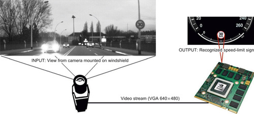 |
| Figure 32.1
Embedded speed-limit-sign recognition system using the GPU.
|
We pursue three different approaches and indicate how we map them to the GPU architecture. We highlight their weaknesses and strengths and compare them in terms of their success rate and runtime. To provide better insight to our comparisons and results, we present example scenes where our pipelines have failed or succeeded. In addition, we indicate how we can tune our parameters to obtain optimum performance, if we are given less/more compute power. Finally, we present scalability results of our approaches by running them on different GPUs with varying compute power.
By performing GPU-based speed-limit-sign recognition, this study serves as a proof of concept for the use of GPU computing in automotive tasks. Today's cars use a combination of digital systems for performing many automotive tasks that are a possible fit for the GPU architecture. Using GPUs instead of these technologies has the following advantages: (1) GPUs allow consolidation that simplifies vehicle design, (2) because of economies of scale, adding a GPU to the production line is cheap, and (3) with their programmability, GPUs offer the ability to rapidly prototype and improve functionality with software updates.
Finally, this study contributes to the field of computer vision by providing different GPU implementations of real-time object recognition on embedded systems. Although we present an application from the automotive computing domain, our approach can also be used to perform similar real-time recognition tasks in different embedded vision domains, such as cell phones and robotics.
In order to investigate the full potential of the GPU for performing speed-limit-sign recognition and to evaluate our results, we pursue three different implementations: (1) a symmetry-focused feature-based approach (referred to as a feature-based approach in the rest of the chapter) that utilizes the fast radial symmetry algorithm
[8]
for detecting circular signs in the scene, (2) a template-based approach that performs FFT correlation between the scene and composite filters generated from the speed-limit-sign templates, and (3) an approach based on the Scale Invariant Feature Transform (SIFT)
[6]
that performs matching of SIFT features extracted from speed-limit-sign templates and the scene.
Currently, we use the feature-based approach to detect only circular shapes. However, as demonstrated by Loy and Barnes
[7]
, fast radial symmetry can be extended to recognize other symmetric shapes, such as octagonal stop signs, diamond-shaped warning signs, and rectangular traffic information signs. On the other hand, the template-based and SIFT-based pipelines are applicable for recognition of planar objects with any shape and text. In addition, the feature-based approach only detects the location of candidate signs, whereas the other two approaches perform recognition of the signs by implementing classification as well as detection. It is possible to combine different stages of these approaches and generate hybrid pipelines. For instance, EU sign detection can be performed by the feature-based pipeline, and then to recognize the sign, the classification stage of the template-based pipelines can be utilized, as shown in
Figure 32.2
.
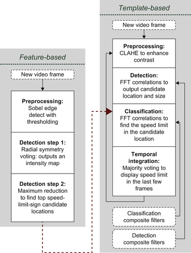 |
| Figure 32.2
Stages of feature-based and template-based approaches. The hybrid pipeline can be constructed by combining the approaches as shown by the dashed line.
|
32.2.1. Feature-Based Pipeline
We have designed a feature-based pipeline to detect circular EU speed-limit signs. Hence, to find locations of these signs, this pipeline finds circular shapes in the scene. Barnes and Zelinsky propose using the fast radial symmetry algorithm to detect circular Australian signs
[1]
. In collaboration with NVIDIA engineers James Fung and Joe Stam, we develop a hardware-accelerated version of this algorithm in this pipeline.
The pipeline consists of three main stages, as shown in
Figure 32.2
. In the first stage, we perform Sobel edge detection with thresholding to extract the edges in the scene. In the next stage, for each edge pixel we perform radial-symmetry voting that outputs an intensity map. Finally, in the last stage, we perform a reduction operation to find maximum intensity values that indicate candidate locations of speed-limit signs. Stages of the feature-based pipeline applied to an example scene are shown in
Figure 32.3
.
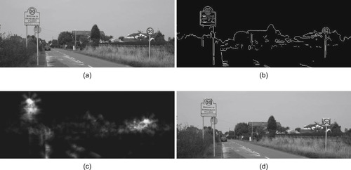 |
| Figure 32.3
Feature-based pipeline stages. (a) An input image from a camera is mounted in a vehicle. (b) An edge map is extracted using a 3 × 3 Sobel filter. (c) Voting results of the radial-symmetry detector. (d) Detected speed-limit signs.
|
Sobel edge detection involves a convolution operation to approximate the absolute gradient magnitude at each pixel. Because convolution is performed for each pixel, this algorithm is data parallel and very suitable to be implemented on the GPU. We use a modified version of the Sobel implementation found in the CUDA Vision Workbench
[2]
to perform edge detection. Likewise, the radial-symmetry algorithm requires a given computation to be performed per edge pixel. In addition to using GPU for performing data-parallel operations of radial-symmetry voting, we also use it to provide hardware acceleration using graphics operations as we will further discuss in
Section 32.3.1
. Finally, reduction can be performed in parallel, as shown in the NVIDIA CUDA SDK, and therefore, we also use the GPU for this operation.
32.2.2. Template-Based Pipeline
To recognize a speed-limit sign, we look for specific images (i.e., speed-limit signs) in the scenes. A natural thing to do is to use these images as templates and match them with the scene. This is our motivation for pursuing a template-based approach. Template matching can be done in the spatial domain with convolution-type operations or in the frequency domain with FFT correlation. In our
approach, we have chosen to perform matching in the frequency space because it provides a faster runtime. This is because performing one multiplication required by FFT correlation is less expensive than computing many match values required by a convolution operation. In addition, we can perform some operations in the frequency domain to improve the performance (i.e.,
k
th-Law nonlinearity, which will be explained later in this section), which is not applicable in the spatial domain.
We further reduce our matching runtime by using composite filters instead of individual templates. Composite filters are generated from several templates and can be thought of as a “combination template.” Using composite filters reduces the number of correlations we need to perform. For instance, we would like to recognize objects when they are seen from different viewpoints. We can search for the object by performing several correlations between the scene and templates that are generated by viewing the object from different viewpoints. However, if we generate a composite filter from these templates, we would need to perform only one correlation instead of performing a correlation for each template. We generate our filters using
k
th-Law nonlinear extension
[4]
of the minimum average correlation energy (MACE)
[9]
filter synthesis algorithm. Using these filters, Javidi
et al
.
[3]
performed the offline recognition of US speed-limit signs with an approach that is similar in spirit to our implementation.
The template-based pipeline has four main stages: preprocessing, detection, classification, and temporal integration, as shown in
Figure 32.2
. We generate composite filters off-line and input them to the detection and classification stages of the system.
Composite filters used in the detection stage are more general than the ones used in the classification stage. They are generated from multiple templates. For instance, to detect EU speed-limit signs,
we use templates 00 and 100, which helps with detecting two-digit and three-digit signs, respectively. The detection composite filter used on EU roads is shown in
Figure 32.5(b)
. On the other hand, each classification composite filter is generated from one specific speed-limit-sign template. The classification composite filter generated for EU speed-limit 60 km/h is shown in
Figure 32.5(c)
. We generate a different group of classification composite filters for each speed-limit sign we would like to recognize. Composite filters in each group have different sizes and in-plane rotations. For each size, we have composite filters with different in-plane rotations. Detection composite filters consist of only one group because all of them are generated from the same templates. This group consists of different sizes of detection composite filters. Both detection and classification composite filters integrate different out-of-plane rotations of the templates, as shown in
Figure 32.4
.
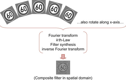 |
| Figure 32.4
Overview of
k
th-Law MACE composite filter generation that integrates different out-of-plane rotations of the template.
|
 |
| Figure 32.5
FFT correlation between scene and
k
th-Law MACE detection composite filter produces a sharp peak in correlation plane.
|
Performing an FFT correlation between the scene and the
k
-Law MACE filter produces a sharp, distinct peak in the correlation plane where the candidate speed-limit sign is located as depicted in
Figure 32.5
. To measure the goodness of the match returned by this correlation, we use peak-to-sidelobe ratio (PSR)
[12]
.
The preprocessing stage enhances the contrast of the scene, and hence, improves the visibility of the signs, by applying Contrast Limited Adaptive Histogram Equalization (CLAHE)
[14]
, as shown in
Figure 32.6
. In the detection stage, we find the location and the size of the candidate sign. We achieve this by performing FFT correlations between the scene and the detection composite filters and then determining the detection filter that returns the maximum PSR. In the classification stage, we perform FFT correlations between the classification composite filters and the part of the scene that includes the candidate sign. We use only the classification filters that have the same size as the candidate sign. If the maximum PSR value is below a certain threshold, we conclude that there are no speed-limit signs in the scene and start processing the next frame. If not, the classification filter with maximum PSR indicates the number displayed by the speed-limit sign in the current scene. An overview of these stages is depicted in
Figure 32.7
.
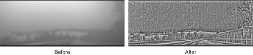 |
| Figure 32.6
After CLAHE is applied, the EU speed-limit 40 km/h becomes more visible.
|
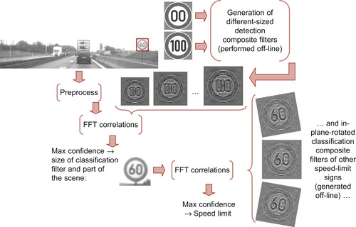 |
| Figure 32.7
Overview of preprocessing, detection, and classification stages of the template-based pipeline for performing EU speed-limit-sign recognition.
|
In the temporal integration stage, we increase the reliability of our results by accumulating the findings from the sequence of frames. For this purpose, we employ a majority-voting technique similar to the one used by Keller
et al
.
[5]
. Each frame votes for the speed-limit number indicated by its classification stage. The maximum PSR determined at this stage is used as the base vote value. If the previous frame also voted for the same number, the vote is increased by multiplying the base value with a constant factor, when one or both of the following conditions are met: (1) the size of the sign is not decreasing or (2) in-plane rotation of the sign remains the same. After all the frames in the sequence are processed, we display the speed-limit number that collected the most votes over a given threshold as the final result. The example in
Figure 32.8
shows how the temporal integration stage helps us display the correct results (i.e., 80 km/h) when some frames return misclassifications (i.e., 30 km/h).
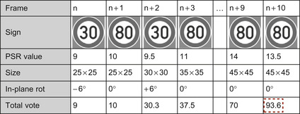 |
| Figure 32.8
An example that shows how the temporal-integration stage of the template-based pipeline works. The results are determined as 80 km/h because it collected the maximum total vote as indicated by the thick-dashed box.
|
Currently, we use optimized C code to apply CLAHE. However, this operation has several data-parallel parts and could be mapped to the GPU to improve runtime. Performing FFT correlations between the scene and
k
th-Law MACE filters also involve data-parallel computations; hence, they are a very good fit for the GPU architecture as will be further discussed in
Section 32.3.2
. In addition, we use the GPU to find the peak in the correlation plane by performing a reduction operation.
Although we present recognition of speed-limit signs with our template-based approach, this pipeline can easily be modified to recognize planar objects with different shapes or text (e.g., other road signs, gas station logos, etc.) as long as we have a template for it. Recognition techniques, which look for particular features of the object, such as shape or color, lack this ability. Hence, we contribute to the computer vision literature by providing a GPU-based implementation of template-based object recognition, which can also be utilized in other application domains.
32.2.3. SIFT-Based Pipeline
In the computer vision literature, Scale Invariant Feature Transform (SIFT) is a commonly used method for performing object recognition. Hence, in order to evaluate our approach, we also implement a SIFT-based speed-limit-sign recognition system on the GPU and compare it with our pipeline.
The SIFT-based pipeline has three main stages: SIFT feature extraction, SIFT matching, and temporal integration. We perform feature extraction and matching by utilizing SiftGPU
[13]
, an open source GPU-based SIFT project. In addition to performing the last stage of this pipeline, we employ a similar technique used in the temporal integration stage of the template-based pipeline. We provide details of the SIFT-based pipeline in a different publication
[10]
.
32.3. Implementation
In this section, we present implementation details of important parts of the feature-based and template-based pipelines. We explain the computation performed in these parts and indicate how we map them to the GPU architecture.
32.3.1. GPU-Accelerated Fast Radial Symmetry
In the feature-based pipeline, both preprocessing and detection are highly parallel processes. Each algorithm operates on a per-pixel basis with no data or control dependencies. Thus, we map both of these algorithms entirely on the GPU in order to take advantage of its many processing cores.
The incoming image is copied over to the GPU's video memory and is mapped as a texture. The first stage, Sobel filter, is a CUDA kernel that runs per pixel. Each pixel samples its immediate neighbors (3 × 3 pixel border) using fast texture sampling. The input image remains as a texture and is unmodified, as it might be needed for classification after successful detection. The result of the Sobel filter is an edge map containing gradient angles and is saved to global video memory. Then, a per-pixel radial symmetry kernel runs using the gradient angle image as its input. Each nonzero element uses the gradient angle stored in the input location to calculate its voting areas. The values calculated at this stage are (x
,
y
) coordinate pairs for the vertices of the voting triangles. Each pixel stores its result in an OpenGL vertex buffer object (VBO). Once the radial-symmetry kernel finishes, OpenGL uses this VBO to draw triangles defined by the (x
,
y
) pairs. When the CUDA-OpenGL interoperability is used, there are no memory transfers between these two stages.
OpenGL binds a pixel buffer object to a texture. The pixel buffer is chosen as the rendering target. With blending enabled, each triangle is rendered with a high-transparency (lowest nonzero alpha) value onto the pixel buffer. The graphics hardware blends together all overlapping triangles, causing these areas to appear brighter. The result here is an intensity map with the accumulated votes of the radial symmetry stage. A large gain here comes from the drawing and blending hardware of the GPU. A high
number of overlapping incremental votes causes contention and serialization in most architectures, but the GPU hardware is optimized for this operation. In this stage, our technique takes full advantage of the present resources in a highly efficient voting strategy. We diagram radial-symmetry voting in
Figure 32.9
.
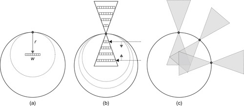 |
| Figure 32.9
Radial symmetry voting. (a) Each pixel votes a distance
r
away with a width
w
. (b) Voting is performed throughout a range of radii. (c) The overall voting pattern of several edge pixels. Note the accumulating votes in the overlapping regions.
|
For the final stage (maxima detection), we use a block maximum reduction where the cumulative voting image
V
is divided into blocks. The reduction is performed per block and returns the index and value of the element with the highest vote total within each block. This process is also parallelized where possible, but becomes serial in its final stages. First, each thread finds the maximum element among its elements in serial. This process occurs concurrently among the
b
blocks covering the entire voting image
V
. This process is applied iteratively until the output is reduced to a desired number of speed-sign candidates. The results are candidate centroids (in
x
,
y
pairs) and are copied back to the host processor. On the host, a reduction is performed to locate the block with the maximum value. That block is then marked as used and is further invalid. The maximum reduction that is performed on the CPU is only an 80 × 60 pixel block and executes fast enough on the host processor as to not affect the overall runtime of the detection process.
The main gain in performance here is the hardware acceleration achieved during the voting stage — calculating voting areas and accumulating the results. The first stage is accelerated by fast texture lookups that do not exhibit many of the common memory drawbacks, such as expensive uncoalesced accesses and boundary condition checking. In the second stage of the voting process, the graphics pipeline performs all interpolating and accumulating calculations. The need for sine and cosine calculations throughout the triangular voting process is completely eliminated and is handled seamlessly by the native rendering hardware of the GPU. This voting process is similar to the Hough Transform calculations performed using the rendering hardware in the OpenVIDIA project
[2]
.
In the detection and classification stages of the template-based pipeline, we perform FFT correlations.
Equation 32.1
shows the formula for computing FFT correlation between a scene and an individual template, where
 indicates the complex conjugate of complex number
C
,
FFT
/
invFFT
denotes forward/inverse Fast Fourier Transforms, × indicate complex multiplication, and
norm
is the FFT normalization.
indicates the complex conjugate of complex number
C
,
FFT
/
invFFT
denotes forward/inverse Fast Fourier Transforms, × indicate complex multiplication, and
norm
is the FFT normalization.

(32.1)
Instead of using individual templates, we use
k
th-Law nonlinear MACE composite filters as explained in
Section 32.2.2
. Using
k
th-Law nonlinearity in our system improves correlation-peak sharpness, illumination invariance, and discrimination ability against impostor objects that look similar to speed-limit signs. In order to compute an FFT correlation between the scene and a
k
th-Law composite filter, we apply a
k
th-Law nonlinear operation to the FFT of the scene before it is multiplied with the complex conjugate of the filter. The nonlinear operation raises the magnitude of the Fourier transform to the power of
k
, while keeping its original phase, as shown in
Equation 32.2
, where complex number
C
is represented in its trigonometric form. In this equation
 and
arg
(C
) indicate magnitude and phase of
C
, respectively.
and
arg
(C
) indicate magnitude and phase of
C
, respectively.

(32.2)
Hence, combining
(32.1)
and
(32.2)
, in order to perform FFT correlation between scene and
k
th-Law nonlinear MACE composite filters, we need to perform the computation shown in
Equation 32.3
.

(32.3)
Computation shown in
Equation 32.3
is a good fit for a GPU architecture because all operations can be done in a data-parallel fashion. To implement this computation on the GPU, we use NVIDIA's CUFFT library to take inverse and forward FFTs. In addition, we use CUDA kernels to apply
k
th-Law nonlinearity to the FFT of the scene, take the complex conjugate of the composite filter in the frequency domain, multiply these two FFTs, and normalize the result of this product; all these processes involve per-pixel operations.
32.4. Results and Discussion
This section consists of several parts. First, we present success rates and runtimes of all pipelines on the footage captured on EU roads. We also provide our initial recognition results of the template-based pipeline on US roads. Next, drawing on the EU speed-limit-sign recognition results, we compare the pipelines by highlighting their strengths and weaknesses. We present interesting scenes from EU roads where both template-based and SIFT-based pipelines performed well/poorly or one of the pipelines outperformed the other. We provide additional interesting scenes from US roads to provide better evaluation of the template-based pipeline. We also explain why template-based and/or SIFT-based approaches failed or succeeded in these particular cases and what kinds of improvements are done to overcome these challenges. Then, we talk about parameters we use in feature-based and template-based
pipelines and how we would tune our parameters if we are given less or more compute power. This is followed by a discussion of scalability results that presents runtimes of the feature-based and template-based pipelines on different GPUs, while performing EU-speed-limit-sign recognition.
32.4.1. Recognition Results
Both EU and US videos we used to report our results are grayscale and filmed under a variety of weather conditions (e.g., rainy, snowy, foggy) and on different road types (country road, highway, city).
The feature-based pipeline returned an 88% detection rate for the footage captured on EU roads. The footage is 43 minutes, includes 164 signs, and consists of 80 clips shot in both daylight and nighttime. The video resolution is 640 × 480. Our detection runtime is 33 fps on an embedded system with an Intel Atom 230 @ 1.67 GHz CPU and an NVIDIA GeForce 9200M GS GPU. Both of these processors are found in low-end laptops and owing to their ultra-low power requirements, are an ideal match for an embedded automotive system.
We have collected results of template-based and SIFT-based pipelines on footage captured from 45 minutes of driving that consists of 69 clips and includes 120 EU speed-limit signs. The video size is 640 × 240. In this dataset we have included only daytime videos (e.g., early morning, noon, late afternoon) in our test set. However, we can also recognize speed-limit signs in nighttime videos if the parameters of the pipelines are properly tuned. We process the footage on a laptop equipped with an Intel Core2 Duo P8600 2.4 GHz CPU and an NVIDIA GeForce 9600M GT GPU, a laptop graphics card comparable in performance to next-generation embedded GPUs. With the template-based approach, we achieved a runtime of 18.5 fps. Our success rate is 90% with no misclassification and false positives. The runtime for the SIFT-based pipeline increases with the number of keypoints extracted from an image. For a frame with moderate complexity, the runtime is around 8 fps. Because the camera capture rate was faster than the runtime of the SIFT-based pipeline, we could not achieve a real-time performance with this approach. An off-line run of the SIFT-based pipeline provided a 75% success rate and returned four misclassifications and nine false positives. A summary of these results is presented in
Table 32.1
.
| Pipeline | Runtime | Success Rate | Misclassifications | False Positives |
|---|---|---|---|---|
| Template-based | 18.5 fps | 90% | 0 | 0 |
| SIFT-based | 8 fps | 75% | 4 | 9 |
In order to demonstrate that the template-based pipeline can be used to recognize different road signs other than EU speed-limit signs, we have also performed recognition of US speed-limit signs. Unlike circular EU speed-limit signs that include only numbers, US ones are rectangular and also include text, as shown in
Figure 32.11(e)
. We have collected our initial results from 54 clips captured on US roads, which include 41 US speed-limit signs. Our success rate is 88% with one misclassification and no false positives. As expected, these results are very similar to the template-based pipeline results collected on EU roads.
32.4.2. Evaluation of Pipelines
Although it can be used only to detect symmetric shapes, the feature-based approach has an advantage of providing a very fast detection rate. The SIFT-based pipeline has the slowest runtime because
it consists of different stages that are computationally intensive. In addition, the SIFT-based approach has a lower success rate mainly for two reasons: (1) SIFT recognition works best when objects have some complexity. However, speed-limit signs have simple shapes and constant color regions. They also mostly appear small in videos. Thus, usually few features can be extracted from these signs, and often the same number of feature matches are returned by different templates, which makes the recognition hard. (2) Because the test videos have low contrast, in the template-based pipeline we employ a preprocessing stage and apply CLAHE to the scene. Applying CLAHE on the template-based pipeline improved our success rate from 65% to 90% and eliminated all misclassifications and false positives. However, we could not use CLAHE in SIFT-based pipelines because CLAHE creates noise that the SIFT-based approach could not handle.
We gain insight on the relative advantages and disadvantages of the template-based and SIFT-based pipelines by comparing their performances on a variety of scenes. On some scenes, both pipelines perform well:
The template-based pipeline recognizes several scenes where the SIFT-based pipeline fails:
However, the SIFT-based method succeeds and the template-based pipeline fails in the following cases:
Finally, some cases cause both pipelines to fail:
• Both methods reject signs with a dominant difference. For instance, in
Figure 32.10(a)
, the thick line that crosses over the whole sign differentiates the end-of-50 sign from a speed-limit sign. Hence, both pipelines reject this sign.
• Both methods also recognize signs with insignificant modifications. For example, in
Figure 32.10(b)
, the small stain in the digit “0” does not affect its recognition.
• The template-based approach is better at recognizing small signs (Figure 32.10(c)
). Many of our tests begin with a small sign that becomes a larger sign as it approaches. However, as the sign
gets closer in succeeding frames, we see increasing viewpoint change, making recognition more difficult. The SIFT-based pipeline suffers in this scenario because it does not benefit from an initial recognition of the sign at small sizes. Although doubling the image size and reducing the initial Gaussian blur in the SIFT-based pipeline helps recognize moderately small signs, these improvements are not effective enough to succeed in smaller signs that can be recognized by the template-based approach.
• Noisy images, caused by effects such as motion blur (Figure 32.10(d)
) and partial shade (Figure 32.10(e)
), are a challenge for vision algorithms. The template-based pipeline is better at handling these different types of noise. Tolerance to noise also allows the template-based approach to use CLAHE as mentioned earlier in this chapter. Applying CLAHE allows the template-based pipeline to succeed in hard cases with very low contrast, such as the sun behind the sign (Figure 32.10(f)
) or a light beam effect (Figure 32.10(g)
). The SIFT-based pipeline benefits from decreasing the threshold used to select potential keypoints in low-contrast cases, but the template-based approach still has superior performance, particularly in very low-contrast scenes.
• The template-based approach also wins in recognizing signs as a whole. The SIFT-based pipeline uses local features to recognize objects; thus, if part of the sign looks like a speed-limit sign, SIFT may misclassify it.
Figure 32.10(h)
shows a 2-meter-width-limit sign that SIFT misclassifies as a 20 km/h speed-limit sign, because of the similarity between the digit “2” in both signs.
• Although concentrating on local features causes the SIFT-based approach to miss global features and fail in the preceding case, local features are beneficial for recognizing partially occluded signs.
Figure 32.10(i)
shows a partially occluded sign because of snow where the SIFT-based pipeline succeeds and the template-based pipeline fails.
• The “SI” in “SIFT” stands for scale invariance: indeed, the SIFT-based pipeline better recognizes signs that initially appear large in the videos as well as the ones with large rotations. To match its performance, the template-based pipeline must be augmented with bigger sizes and larger rotations in our composite filters, which in turn would increase our runtime.
• Although the template-based pipeline is better at recognizing small signs, very small signs perform equally poorly on both pipelines. We tried introducing additional composite filters with smaller sizes in the template-based pipeline, but we found this was counterproductive as it introduced misclassifications and false positives.
• Both pipelines perform poorly when a significant part of the sign is missing. Bright sunshine in
Figure 32.10(j)
results in failure for both approaches.
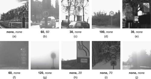 |
| Figure 32.10
Template-based and SIFT-based pipeline results shown in
bold
and italic, respectively.
|
To provide a better evaluation of the template-based pipeline, we show interesting scenes captured from US roads in
Figure 32.11
. There are several hard cases where the template-based pipeline succeeds. For instance, our system performs well even if the shape of the sign is slightly deformed, as in
Figure 32.11(a)
where the sign is bent along the horizontal axis. It also succeeds in recognizing signs that have large rotations, as in
Figure 32.11(b)
. In addition,
Figure 32.11(c)
demonstrates that our system can recognize signs located in different parts of the scene.
On the other hand, there are some hard scenes where our template-based approach fails. Because in some cases, US speed-limit signs have nonuniform shapes and fonts, our system cannot successfully
recognize them. For instance, our system uses filters generated from standard templates (like the one shown in
Figure 32.11(e)
) to recognize
Figure 32.11(d)
. However, in order to successfully recognize a sign like this, we need to include templates with wider text and smaller numbers. Our system also fails in
Figure 32.11(f)
because the sign has a very small size.
Figure 32.11(g)
shows another scene where our system is not successful. In order to recognize this sign, we need to expand the range of in-plane rotations we cover with our filters.
Finally, in some US scenes (Figure 32.11(h–j)
) speed limits are indicated with several different special signs. In order to make our system applicable to these cases, we can easily add filters generated from templates of these signs. This flexibility of the template-based pipeline makes our approach a good fit for speed-limit-sign recognition on US roads involving several different sign types.
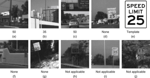 |
| Figure 32.11
Template-based pipeline results of example scenes on US roads.
|
32.4.3. Parameters and Tuning for Less/More Compute Power
We can make the best use of the limited resources of underlying hardware by fine-tuning the parameters of our pipelines based on the trade-off between the runtime and success rate. If given a GPU with less or more compute power, we can contract or extend parameters of the pipelines to achieve the optimum real-time performance.
To leverage the fast detection rate of the feature-based pipeline, we can use a hybrid pipeline for the recognition of EU speed-limit signs, as shown in
Figure 32.2
. In this pipeline, the detection is performed by the feature-based approach, and classification is performed by the classification stage of the template-based pipeline. In such an approach, increasing the number of examined candidates improves the recognition rate. Because of the parallel implementation of the maximum reduction stage, the runtime of the feature-based detection is invariant to the number of candidates detected. However, there is an increase in the overall execution time because the classification stage needs to process an
increasing number of candidates. Thus, in the hybrid pipeline, if we are given less/more compute power, we can adjust the number of candidates detected to make the best use of hardware resources.
The template-based pipeline consists of modular components and the parameters of these components can be adjusted to achieve the optimum performance. In this pipeline, we compute FFT correlations between the scene and composite filters that have different sizes and in-plane rotations. We used five different sizes and three different in-plane rotations while performing EU speed-limit-sign recognition. Additionally, in the generation of composite filters, we used three different out-of-plane rotations along the X axis and seven different rotations along the Y axis. We include more rotations along the Y axis because signs usually have larger rotations along the vertical axis than the horizontal one.
There are few differences between the template-based pipeline parameters that we used for US and EU roads. US signs are rectangular, and therefore, we have noticed that in-plane rotations produce bigger energy changes in US signs than they do in circular EU signs. Hence, for US roads we have reduced in-plane rotations of our classification filters. To further improve accuracy, we could expand the range of in-plane rotations that we cover by generating in-plane rotations of detection filters. Another difference is that we used different templates for generating EU and US detection filters. This is because EU signs have two and three digits that always end with 0, whereas US signs always have two digits that end with 0 or 5. As on EU roads, we also have used five different filter sizes on US roads.
In the template-based approach, if we are given less compute power, it is better to reduce our runtime by dropping bigger sizes from the parameter list than to decrease the number of frames we process per second. We prefer to drop bigger sizes than the smaller ones because signs in the videos usually appear small and get bigger as we get closer. Hence, if we can successfully classify the signs while they are small, we may not need the bigger sizes to correctly recognize most of them. If we are given more compute power to pursue the template-based approach, we can achieve a higher success rate in the following ways: (1) increase the processing frame rate, (2) add larger sizes of signs to our parameter list, (3) generate additional composite filters that cover larger OOP rotations that current filters do not cover, and (4) strengthen the statistical model of the temporal integration stage by employing techniques like a hidden Markov model. We would add bigger sizes rather than smaller ones because the ones that are smaller than what we currently have in our parameter list are too small to successfully discriminate the signs, and they introduce misclassifications and false positives. In addition, we would not add larger OOP rotations to current filters because it also hurts the discrimination capability of the filters by introducing high-energy changes.
32.4.4. Scalability of Feature-Based and Template-Based Pipelines
We perform EU speed-limit-sign recognition on different GPUs with varying compute power to measure the scalability of our approaches.
Performance of the feature-based pipeline scales close to ideal, as shown in
Table 32.2
. We do not achieve an ideal speedup (i.e., 4x speedup in runtime for a 4x increase in the number of processing cores) because there are several overheads and bottlenecks introduced in a larger device. First, there is a larger overhead for scheduling threads across four streaming-multiprocessors (SMs), as opposed to just a single SM. Second, distributing operands to the threads awaiting them involves a more complicated on-chip network. Third, with more threads executing at once, there is higher memory contention and certain reads or writes could end up being serialized if the memory controller cannot service all requests simultaneously.
| GPU | SMs | Speedup |
|---|---|---|
| 9200M GS | 1 | – |
| 9400M G | 2 | 1.8x |
| 9600M GS | 4 | 3.2x |
We also measure the effect of changing the number of SMs on the GPU runtime and performance of the template-based pipeline, as shown in
Table 32.3
. Our base configuration runs on a GeForce
9600M GT, a GPU with four SMs. Our GPU runtime is 3 × lower when we run our code on a GeForce 8400M GS GPU that has two SMs. Even though we have 2 × fewer SMs, we are getting more than 2 × slowdown because we replaced the GT model of the 4-SM GPU with the GS model of the 2-SM GPU. The extra slowdown can be explained by the fact that GS models have slower clock rates and memory. The overall runtime on the GeForce 8400M GS is 8 fps. With this speed we can process only 60% of the frames in real time. Because we process fewer frames, we lower the threshold that we use in the temporal integration stage to get an accurate performance measure. Even though we cannot process 40% of the frames, the success rate is decreased by only 6.67%. In addition, only one misclassification and one false positive are introduced. These results show that our system can still return reliable and high performance, even if we have a 2-SM GPU.
To measure the effect of having more SMs on the GPU runtime, we run our code on a GeForce 8800 GTX GPU, which has 16 SMs. Even though we have 4x more SMs in this architecture, our runtime is only 2.3x faster. The reason for not getting a speedup closer to 4x is that in the classification stage, we cannot utilize the full power of the 16-SM GPU. In this stage we perform many small FFT correlations between different classification filters, and the small part of the scene that has the potential sign. Running the kernels on this small amount of data does not create enough work to fill the 16-SM GPU. Hence, in order to get a higher speedup on this architecture, we can perform a batch computation in the classification stage. We can achieve this by gathering the small amounts of data into one big chunk and performing one big FFT correlation instead of many small ones.
32.5. Conclusion and Future Work
We performed real-time speed-limit-sign recognition on a resource-constrained embedded system with a low-end GPU as the main processing unit. To provide fast runtimes and make efficient use of the
underlying limited hardware resources, we exploited the inherent parallelism in the recognition process using data-parallel algorithms that are suitable for the GPU architecture. We pursued three different pipelines in order to evaluate our results and investigate the full potential of the GPU for performing speed-limit-sign recognition. The feature-based and template-based pipelines returned real-time performance using a low-end GPU, which could not be achieved by their CPU-based implementations. The SIFT-based pipeline provided a basis for evaluation of recognition results of our template-based approach, which achieved a higher success rate with a faster runtime. By providing results of US speed-limit-sign recognition, in addition to the results collected from EU roads, we demonstrated that the template-based approach can easily be adapted to recognize road signs with different shapes and the inclusion or exclusion of text. We contributed to the computer vision literature by presenting a novel GPU-accelerated implementation of the fast radial-symmetry algorithm and GPU-based implementation of template matching in the frequency domain that utilizes nonlinear composite filters.
This study serves as a proof of concept for the use of GPU computing in automotive tasks. However, in order to make the best use of an embedded GPU in the cars, we should be able to simultaneously run multiple other automotive tasks that are a good fit for the GPU architecture. Examples of such tasks include other computer vision applications, such as performing optical flow for pedestrian detection; signal processing applications, such as speech recognition; and graphics applications, such as infotainment systems. Using the GPU over the digital systems that currently perform these tasks has several advantages, as explained in
Section 32.1
. Hence, in the future, we would like to work on developing software support for our data-parallel embedded system that can run multiple tasks simultaneously while delivering real-time throughput and/or latency guarantees, which we believe is an understudied research area in the field of GPU computing.
References
[1]
N. Barnes, A. Zelinsky,
Real-time radial symmetry for speed sign detection
,
In:
Proceedings of the 2004 IEEE Intelligent Vehicles Symposium
Parma, Italy, IEEE, Los Alamitos, CA
. (2004
), pp.
566
–
571
.
[2]
J. Fung, S. Mann, C. Aimone,
OpenVIDIA: parallel GPU computer vision
,
In:
Proceedings of the 13th Annual ACM International Conference on Multimedia
Singapore
. (2005
)
ACM
,
New York
, pp.
849
–
852
.
[3]
B. Javidi, M.-A. Castro, S. Kishk, E. Perez, Automated detection and analysis of speed limit signs, Technical Report, University of Connecticut, Storrs, CT, JHR 02 (2002) 285.
[4]
B. Javidi, D. Tarjan,
Distortion-invariant pattern recognition with fourier-plane nonlinear filters
,
Appl. Opt.
35
(2
) (1996
)
318
–
331
.
[5]
C.G. Keller, C. Sprunk, C. Bahlmann, J. Giebel, G. Baratoff,
Real-time recognition of U.S. speed signs
,
In:
Proceedings of the 2008 IEEE Intelligent Vehicles Symposium, IEEE
Los Alamitos, CA
. (2008
), pp.
518
–
523
.
[6]
D.G. Lowe,
Distinctive image features from scale-invariant keypoints
,
Int. J. Comput. Vision
60
(2
) (2004
)
91
–
110
.
[7]
G. Loy, N. Barnes,
Fast shape-based road sign detection for a driver assistance system
,
In:
Proceedings of the 2004 IEEE/RSJ International Conference on Intelligent Robots and Systems (IROS), IEEE
Los Alamitos, CA
. (2004
), pp.
70
–
75
.
[8]
G. Loy, A. Tarjan,
Fast radial symmetry for detecting points of interest
,
Trans. Pattern Anal. Mach. Intell.
25
(8
) (2003
)
959
–
973
.
[9]
A. Mahalanobis, B.V.K. Vijaya Kumar, D. Casasent,
Minimum average correlation energy filters
,
Appl. Opt.
26
(17
) (1987
)
3633
–
3640
.
[10]
P. Muyan-özçelik, V. Glavtchev, J.M. Ota, J.D. Owens,
A template-based approach for real-time speed-limit-sign recognition on an embedded system using GPU computing
,
In:
Proceedings of the 32nd Annual German Association for Pattern Recognition (DAGM) Symposium
(2010
)
Springer-Verlag
,
Berlin, Heidelberg, Germany
, pp.
162
–
171
;
LNCS 6376
.
[11]
J.D. Owens, D. Luebke, N. Govindaraju, M. Harris, J. Krüger, A.E. Lefohn,
et al.
,
A survey of general-purpose computation on graphics hardware
,
Comput. Graph. Forum
26
(1
) (2007
)
80
–
113
.
[12]
M. Savvides, B.V.K. Vijaya Kumar, P. Khosla,
Face verification using correlation filters
,
In:
Proceedings of the Third IEEE Conference on Automatic Identification Advanced Technologies (AutoID), IEEE
Los Alamitos, CA
. (2002
), pp.
56
–
61
.
[13]
C. Wu, ,
SiftGPU
,
A GPU Implementation of Scale Invariant Feature Transform (SIFT)
. (2007
)
University of North Carolina at Chapel Hill
,
Chapel Hill, NC
;
http://cs.unc.edu/~ccwu/siftgpu
.
[14]
K. Zuiderveld,
Contrast limited adaptive histogram equalization
,
In:
Graphics Gems IV
(1994
)
Academic Press
,
Boston, MA
, pp.
474
–
485
.
..................Content has been hidden....................
You can't read the all page of ebook, please click here login for view all page.