
Chapter 40. GPU Acceleration of Iterative Digital Breast Tomosynthesis
Dana Schaa, Benjamin Brown, Byunghyun Jang, Perhaad Mistry, Rodrigo Dominguez, David Kaeli, Richard Moore and Daniel B. Kopans
Iterative digital breast tomosynthesis (DBT) is a technology that mitigates many of the shortcomings associated with traditional mammography. Using multiple low-dose X-ray projections with an iterative maximum likelihood estimation method, DBT is able to create a high-quality, three-dimensional reconstruction of the breast. However, the usability of DBT depends largely on making the time for computation acceptable within a clinical setting.
In this work we accelerate our DBT algorithm on multiple CUDA-enabled GPUs, reducing the execution time to under 20 seconds for eight iterations (the number usually required to obtain an acceptable quality reconstructed image). The algorithm studied in this work is representative of a general class of image reconstruction problems, as are the thread-mapping strategies, multi-GPU considerations, and optimizations employed in this work.
40.1. Introduction
In 2005, breast cancer claimed the lives of 41,116 women in the United States; it trailed only lung cancer as the leading cause of cancer mortality among US women
[3]
. However, this statistic belies the high five-year survival rate for patients treated for early-stage breast cancer
[5]
. This disparity illustrates the continuing need to improve breast cancer screening techniques.
Screening mammography has been shown by randomized-controlled trials to reduce breast cancer mortality rates in the range of 30–50% since 1985. In spite of its successes, mammography has been criticized for high false positives and imperfect sensitivity. Both of these can be largely attributed to structural noise (i.e., the superimposition of normal breast tissue), which can hide lesions. Although steps have been taken to improve the efficacy of conventional screening methods, the emotional, physical, and financial burdens caused by the low positive predictive value for biopsies, unnecessary callbacks, and undetected cancers remain high
[7]
.
Digital breast tomosynthesis (DBT) is a technology that takes a series of X-ray projections to acquire information about the breast structure. A reconstruction method is required to combine these projections into a three-dimensional image.
Figure 40.1
shows the data acquisition process used for DBT. Although clinical trials on DBT have shown promising results, the primary obstacle to using DBT in a clinical setting is implementing a reconstruction process that is both accurate and fast. Note that this trade-off is not unique to DBT, but must be considered in many different medical imaging algorithms and domains
[4]
and
[6]
.
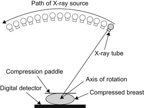 |
| Figure 40.1
Setup of data acquisition for DBT. An X-ray source covers a (40°) arc emitting low-dose X-rays at 15 locations. Fifteen corresponding projections are acquired by a high-resolution digital detector.
|
Traditionally, filtered backprojection (FBP) and its variants have been used for tomographic reconstruction. These methods have become standard reconstruction techniques owing to their ability to produce acceptable images and employ analytical models that simplify reconstructions by approximating the scanner geometry. In contrast, iterative methods use much more precise geometric models and iterate on error correction until they produce projections of high similarity to the original scans. As such, iterative techniques produce higher-quality images, but are much more computationally intensive. For DBT, a maximum-likelihood-based iterative method has been shown to be very effective at suppressing artifacts
[2]
. An overview of the algorithm is provided in
Section 40.2
.
Despite the advantages of iterative techniques for reconstruction, clinical acceptance has been slow owing to the high computational overhead associated with iterative reconstruction. Initial reconstructions performed at Massachusetts General Hospital took 48 hours on Pentium IV workstations. To overcome this barrier to clinical feasibility, parallel computing approaches were developed and implemented on Beowulf clusters
[8]
.
Although the cluster-based parallel approach reduced reconstruction time, this speedup was achieved only through significant hardware cost, energy consumption, and hardware/software maintenance expense. In contrast to traditional parallel computing platforms, graphics processing units (GPUs) have gained acceptance owing to their low start-up cost, lower power demands, and low maintenance costs (versus a cluster of systems). GPUs are very well suited for data-parallel applications such as DBT. Advances in GPU hardware have been coupled with the development of software frameworks that have reduced the parallel programming effort associated with GPU computing. In this work, we highlight the benefits and trade-offs associated with migrating an iterative DBT reconstruction algorithm used in medical clinics to a GPU. We also explore the benefits obtained on different GPU platforms, as well as on systems equipped with multiple GPUs.
The next section describes the algorithm used for image reconstruction in DBT.
Section 40.3
discusses issues related to porting and optimizing the code for single-GPU and multi-GPU acceleration and presents performance results, and
Section 40.4
concludes this chapter.
40.2. Digital Breast Tomosynthesis
The iterative digital breast tomosynthesis (DBT) algorithm used in our work is an IRT that uses an iterative maximum likelihood estimation method (MLEM)
[1]
. The MLEM is a statistical method that continually corrects a guess of a 3-D image (representing patient tissue) until it produces simulated X-ray projections that highly correlate with the original X-ray projections that were received by the detector. The 3-D image consists of volumetric pixels (voxels) of attenuation coefficients that determine how that portion of the image affects X-ray intensity. The reconstruction has two phases, a forward projection and a backward projection, that are iteratively executed until the error level is below a quality threshold (typically requiring on the order of eight iterations).
Figure 40.2
shows a flowchart of the iterative DBT algorithm used in this work.
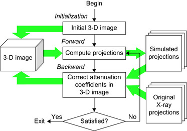 |
| Figure 40.2
A high-level description of iterative digital breast tomosynthesis algorithm and data usage.
|
The forward projection phase takes an initial guess of the 3-D image and uses it to generate simulated X-ray projections that would be obtained if this were the object actually being irradiated. The backward projection phase then uses the projected data from the forward phase to correct the guess of the image
[7]
.
In the backward projection phase, the MLEM algorithm solves the likelihood function:
 for the probability (P
) of producing the projections (Y
) received by the digital detector with the attenuation coefficients (u
) for the reconstructed 3-D image. The maximized solution of
Equation 40.1
defines an adjustment to the guess of the 3-D image whose projection data is the most similar to the projections obtained by the digital detector. The full details of the likelihood function can be found in
[2]
.
for the probability (P
) of producing the projections (Y
) received by the digital detector with the attenuation coefficients (u
) for the reconstructed 3-D image. The maximized solution of
Equation 40.1
defines an adjustment to the guess of the 3-D image whose projection data is the most similar to the projections obtained by the digital detector. The full details of the likelihood function can be found in
[2]
.
(40.1)
After the desired error threshold is reached, the resulting 3-D image is then viewable by a physician, who can step through each cross-sectional region in search of tumorous tissue.
Figure 40.3
compares a 2-D image obtained using traditional single-angle mammography with the 45 cross-sectional slices of the reconstructed image obtained using the iterative DBT algorithm that removes superimposed structures to permit detection.
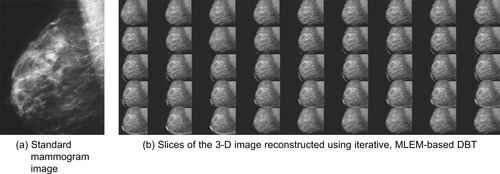 |
| Figure 40.3
A comparison of iterative DBT to traditional mammography. Although traditional mammography produces a 2-D composite of the breast tissue that introduces structural noise and can hide tumors, iterative DBT produces a 3-D image that enables the visualization of cross-sectional areas of the tissue.
|
40.3. Accelerating Iterative DBT using GPUs
40.3.1. Experimental Setup
NVIDIA's most popular computing framework is CUDA C, a general-purpose programming API that allows a programmer to utilize the GPU using an extension of the C programming language. The programming model is based on a massively multithreaded paradigm, where thousands or more threads are created, divided into groups, and run on single instruction multiple data (SIMD) hardware. The term
single instruction multiple thread
(SIMT) is used when referring to the fusion of the multithreaded execution model and SIMD hardware.
The test bed for our reconstruction algorithm is the Medusa GPU Cluster at Northeastern University. Each node of the cluster contains two quad-core Intel Xeon CPUs running at 2.27GHz and has 24GB of DDR3 RAM. A compute node is connected to two NVIDIA Tesla S1070 GPU units, allowing access to eight GPUs from a single node. Each of the four GPUs in the S1070 has 240 streaming processor cores divided among 30 streaming multiprocessors (SMs), and 4GB of graphics memory.
40.3.2. Thread Mapping for GPU Execution
In GPU computing, thread mapping is a crucial decision point for hardware utilization, and therefore, performance. In the forward projection phase, we map threads to the dimensions of the detector cells of the X-ray detector. There is a one-to-one correspondence between detector regions and projection data; thus, roughly 3 million threads are created for each of the 15 forward projections. For GPUs with smaller amounts of memory (less than 2GB), the data for the entire set of projections cannot fit into the GPU memory at once, so segmenting of the computation is required — this is naturally accomplished by computing each of the 15 projections one at a time and swapping them off of the GPU after computation is complete. This is not an issue for GPUs with larger memory capacities.
During the backward projection phase we map threads to image voxels, where a single thread computes the contributions of all X-ray source positions to the attenuation coefficient of a voxel. For the backward phase, creating one thread per voxel has a number of advantages over the detector-based mapping used in forward projection. If the detector-based mapping were used in the backward phase, each thread would compute a portion of the attenuation coefficient for all voxels it encountered on its path between source and detector. Doing so would require the use of atomic updates, which degrade performance, or require multiple 3-D images to be kept (one per projection) that would have to be merged to obtain the final image. Merging the data requires both extra calculation and larger data transfers. Further, because multiple rays from the same projection can impact a voxel, synchronization would still be required to ensure coherent updates. Using a voxel-based mapping avoids these limitations. Using the voxel-based approach also allows segmenting of the 3-D image into 2-D slices for GPUs with smaller memories and for multi-GPU execution.
Other data segmentation techniques are indeed possible (as shown in
[8]
for distributed environments), though the most effective require dynamically determining the boundaries of segments at runtime based on the geometry of the X-ray sources, or otherwise, suffer from blurred reconstruction at segment boundaries. Instead, the mappings presented here have proven to be very effective when targeting GPU and multi-GPU environments.
40.3.3. Optimizing with Texture Memory
When data on the GPU is accessed through the texture unit, additional data with spatial locality are automatically cached on chip in the texture cache. If cached data are accessed by a thread from the same SM, it can be retrieved from the cache without putting any pressure on the global memory bus.
In the backward projection algorithm used by DBT, when the path from the source to the detector cell falls between multiple vertices of the Cartesian grid, data from each vertex contribute to the calculation (as shown in
Figure 40.4
). Depending on the proximity to each vertex, the values retrieved are given a weight to determine their influence on the final value. Because the weights of the values vary per thread and are determined live, we cannot take advantage of hardware interpolation that would otherwise reduce the number of accesses. However, if threads with spatial locality are grouped on the same SM, then multiple threads will end up accessing data from the same region, and using texture memory will serve to decrease pressure on the global memory bus.
 |
| Figure 40.4
Calculating the intensity of X-rays from source to detector requires considering multiple voxel values in each cross-sectional slice of the image.
|
Another benefit of texture memory is that boundary conditions can be handled automatically by hardware. For example, if an out-of-bounds index is accessed through the texture unit, the unit can be programmed to return the edge-pixel value, to return zero (using the CUDA C construct called
surfaces
), or to cause the kernel to fail. Aside from the obvious reduction of code complexity, removing conditional statements is generally an important optimization on current GPU SIMD hardware because conditionals cause thread divergence and prevent the processing units from performing meaningful work. Algorithms
1
and
2
show the code for bounds checking in DBT when global memory is used and the removal of conditionals when texture memory is used, respectively.
// When accessing global memory, bounds must be checked before data can be retrieved.
// The pixels are weighted using the values w1, w2, w3, and w4, respectively.
if
x
1 ≥ 0
AND
x
2 <
imageWidth
AND
y
1 ≥ 0
AND
y
2 <
imageHeight
then
tmp
=
image
(x
1,
y
1) *
w
1 +
image
(x
1,
y
2) *
w
2 +
image
(x
2,
y
1) *
w
3 +
image
(x
2,
y
2) *
w
4
else if
x
1 ≥ 0
AND
x
2 <
imageWidth
AND
y
2 ==
imageHeight
then
tmp
=
image
(x
1,
y
1) *
w
1 +
image
(x
1,
y
2) *
w
2
else if
x
1 ≥ 0
AND
x
2 <
imageWidth
AND
y
2 == 0
then
tmp
=
image
(x
2,
y
1) *
w
3 +
image
(x
2,
y
2) *
w
4
else if
x
2 ==
imageWidth
AND
y
1 ≥ 0
AND
y
2 <
imageHeight
then
tmp
=
image
(x
1,
y
1) *
w
1 +
image
(x
2,
y
1) *
w
3
else if
x
2 == 0
AND
y
1 ≥ 0
AND
y
2 <
imageHeight
then
tmp
=
image
(x
1,
y
2) *
w
2 +
image
(x
2,
y
2) *
w
4
end if
Algorithm 2.
Snippet of code from a kernel accessing data in texture memory. The use of texture memory allows removal of bounds-checking code.
// using CUDA
surfaces
and the
cudaBoundaryModeZero
parameter.
// The pixels are weighted using the values w1, w2, w3, and w4, respectively.
val
1 =
surf
2
Dread
(image
,
x
1,
y
1,
cudaBoundaryModeZero
) *
w
1
val
2 =
surf
2
Dread
(image
,
x
1,
y
2,
cudaBoundaryModeZero
) *
w
2
val
3 =
surf
2
Dread
(image
,
x
2,
y
1,
cudaBoundaryModeZero
) *
w
3
val
4 =
surf
2
Dread
(image
,
x
2,
y
2,
cudaBoundaryModeZero
) *
w
4
tmp
=
val
1 +
val
2 +
val
3 +
val
4;
In the case of DBT, using texture memory provided a very large performance gain on a CUDA architecture of compute capability 1.3 (Tesla S1070), and a significant (although much smaller) benefit on a Fermi architecture of compute capability 2.0 (GTX 480). The GTX 480 memory system features automatic caching for global memory that stores accessed data in a shared L2 cache and also in an on-chip, low-latency L1 cache. Because the automatic caching takes advantage of some spatial locality, it has an effect similar to the texture cache, and we see less benefit from using the texture unit on the GTX 480 than on the Tesla S1070 architecture.
Using the texture unit to handle boundary conditions, we were able to remove many of the conditional statements for the DBT kernel. Interestingly, removing these conditional statements actually showed a slight decrease in performance compared with the texture approach with conditionals in place. The reason for the decrease in performance is the memory-bound execution profile of the DBT application. Relative to the texture cache access time, the time to compute conditional outcomes is small because the texture cache is not a low-latency cache. Leaving the conditionals in place could possibly save up to two texture accesses for many threads, and although accesses to texture cache decreases off-chip memory traffic, the time to access the cache is still on the order of an off-chip memory access.
Figure 40.5
shows the performance benefits for the algorithm before and after mapping the forward and backward projections to texture memory on the S1070 and GTX 480 GPUs.
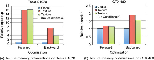 |
| Figure 40.5
A performance comparison across optimizations and hardware. The baseline algorithm (Global
) reads data from global memory, the
Texture
optimization reads data from texture memory, and
Texture
(No Conditionals
) uses the bounds-checking feature of the texture unit to remove conditional statements from the algorithm.
|
40.3.4. Acceleration with Multiple GPUs
Computing with multiple GPUs allows the computation to be split based on the properties of the thread mappings discussed previously, in which projections and image slices are treated as units (i.e., in forward projection, projections are split between GPUs, and in backward projection, slices of image voxels are split between GPUs).
Figure 40.6
shows the distribution of slices on up to eight GPUs. If all GPUs are not fed the same number of slices, then we are concerned only with the GPU with the largest number of slices because it will take the longest to execute. In addition to the number of slices per GPU,
Figure 40.6
also shows the speedup for the computation of the algorithm when communication is not considered (this becomes relevant as the GPU moves on chip with the CPU and shares the same memory space). Notice that the forward projections per GPU line in
Figure 40.6
show that for five to seven GPUs, at least one GPU must compute three projections. In these cases, we see no speedup for forward projection, and in fact, performance actually suffers slightly owing to the overhead of the extra devices.
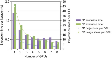 |
| Figure 40.6
The distribution of two-dimensional data and computational speedup in a multi-GPU environment.
|
In order for the thread mappings to work in multi-GPU execution, the results from both the forward and backward projection phases must be sent to the CPU for synchronization after the phase completes. Once the results are synchronized, they must then be broadcast to all GPUs to be used in the next phase. After the forward projection, locally computed projections along with corresponding absorption values (associated with each detector cell) must be synchronized and broadcast, and after the backward projection, the same must happen with the reconstructed image.
Equations 40.2
and
40.3
describe the amount of data (S
) that must be communicated based on the number of GPUs (N
) in each algorithm phase, respectively. The first term in each equation is data that must be synchronized on the CPU (each GPU contributes a part), and the second term is the synchronized data that must be sent to each of
N
GPUs involved in the computation.
Figure 40.7
represents these values graphically for up to eight GPUs.

(40.2)
(40.3)
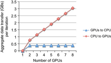 |
| Figure 40.7
The amount of data that must be communicated in the iterative DBT algorithm as the number of GPU scales.
|
Figure 40.8
shows a flowchart of the parallel DBT algorithm. This charts where computation can be parallelized between GPUs and when communication must occur.
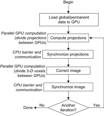 |
| Figure 40.8
Diagram of the iterative multi-GPU DBT algorithm annotated with parallel computation and communication phases.
|
There is the potential that the communication overhead may lead to performance degradation as more GPUs are added. For the DBT algorithm, the amount of data that needs to be communicated increases in a linear fashion as more GPUs are added (see
Figure 40.7
). However, after four GPUs are used, the communication overhead from this algorithm plateaus owing to the system configuration. The NVIDIA compute node of the Medusa cluster has two Tesla S1070s (four GPUs each) each on a dedicated x16 PCIe 2.0 slot. Because the S1070s are on separate PCIe lanes, using GPUs on the second S1070 does not contribute any additional communication overhead.
Figure 40.9
shows the overall iteration time broken down into computation and communication for the algorithm as more GPUs are added.
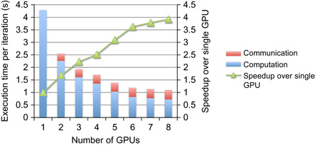 |
| Figure 40.9
The execution time and speedup of iterative DBT on Tesla S1070s for up to eight GPUs.
|
40.4. Conclusions
DBT has demonstrated advantages over traditional mammography. Using roughly the same radiation dose as a 2-D mammogram (the current imaging standard), we can analyze breast tissue structure in three dimensions. This allows the radiologist to “peel away” layers of structural noise, reducing the likelihood of both false positives and false negatives. Through GPU acceleration, we have been able to reduce both the resources and time required to perform high-quality DBT reconstructions.
The performance gains obtained from using GPUs to accelerate iterative MLEM-based DBT reconstruction have been so impressive that time is no longer the dominant concern for clinical application. This work has demonstrated that DBT reconstruction can be less costly and more accurate, while also completing reconstruction in a reasonable amount of time. Given that we have been successful in addressing the computational demands of IRT for DBT, we can focus on additional ways to improve the quality of care for patients, such as consolidating the imaging and follow-up visits, enabling new technologies (such as computer-aided biopsies), or using redundant GPU execution to prevent errors.
Acknowledgments
This work was supported in part by an NSF ERC Innovation Award EEC-0909990, the Institute for Complex Scientific Software, NVIDIA for hardware donations, and The Bernard M. Gordon Center for Subsurface Sensing and Imaging Systems, under the Engineering Research Centers Program of the National Science Foundation (Award Number EEC-9986821). The authors would also like to thank Nicholas Moore at Northeastern University for his contributions and the editors for their constructive comments. The authors also acknowledge Volodymyr Kindratenko from the NCSA for providing access to the the Fermi-based system used in this work.
References
[1]
L. Le Cam,
Maximum likelihood — an introduction
,
ISI Rev.
58
(2
) (1990
)
152
–
171
.
[2]
T. Wu, A. Stewart, M. Stanton, T. McCauley, W. Phillips, D.B. Kopans,
et al.
,
Tomographic mammography using a limited number of low-dose cone-beam projection images
,
Med. Phys.
30
(2003
)
365
.
[3]
Centers for Disease Control and Prevention
,
1999–2005 Cancer incidence and mortality data
,
http://apps.nccd.cdc.gov/uscs/
(2009
)
.
[4]
B. Jang, D. Kaeli, S. Do, H. Pien,
Multi-GPU implementation of iterative tomographic reconstruction algorithms
,
In:
ISBI'09: Proceedings of the Sixth IEEE International Conference on Symposium on Biomedical Imaging
(2009
)
IEEE Press
,
Piscataway, NJ
, pp.
185
–
188
.
[5]
D.B. Kopans,
Breast imaging
.
third ed.
(2007
)
Lippincott, Williams & Wilkins
,
Philadelphia, PA
.
[6]
J.-B. Thibault, K.D. Sauer, C.A. Bouman, J. Hsieh,
A three-dimensional statistical approach to improved image quality for multislice helical CT
,
Med. Phys.
34
(11
) (2007
)
4526
–
4544
.
[7]
T. Wu, R. Moore, E. Rafferty, D. Kopans,
A comparison of reconstruction algorithms for breast tomosyn-thesis
,
Med. Phys.
31
(9
) (2004
)
2636
–
2647
.
[8]
J. Zhang, W. Meleis, D. Kaeli, T. Wu,
Acceleration of maximum likelihood estimation for tomosynthesis mammography
,
In:
International Conference on Parallel and Distributed Systems (ICPAD'06), IEEE Computer Society
Minneapolis, MN
. (2006
), pp.
291
–
299
.
..................Content has been hidden....................
You can't read the all page of ebook, please click here login for view all page.