
The Anatomy of the Landing Gear
Abstract
The chapter presents important information required to properly select wheels, tires, and brakes for aircraft. Methodologies to allow the designer to better size and select these landing gear components are introduced. Additionally, a number of important concepts regarding fixed and retractable landing gear design are presented, in order to ensure reader familiarity before beginning the layout of the landing gear. Then, a cookbook methods to place the nose, main, and tail wheels of the airplane, for a conventional, taildragger, and monowheel configurations is presented. Finally, methods to calculate the reaction loads for the landing gear and to evaluate the airspeed required to rotate the airplane during T-O are presented as well.
Keywords
Tricycle; taildragger; monowheel; tandem; outriggers; wheel; tire; brake; caliper; fixed; retractable; tire inflation pressure; wheel track; wheel base; main landing gear; nose landing gear; tail wheel; castering; shimmy damper; leaf-spring; oleo-strut; ground-loop; dynamic stability
Outline
13.1.1 The Content of this Chapter
13.1.2 Landing Gear Arrangement
13.1.3 Landing Gear Design Checklist
Landing Gear Component Vendors
Tires and Tire Inflation Pressure
13.2 Tires, Wheels, and Brakes
13.2.1 Important Dimensions and Concepts for Landing Gear Design
Castering Nose and Tail Wheels
13.2.2 Retractable Landing Gear
13.2.3 Types and Sizes of Tires, Wheels and Brakes
13.2.4 Types of Landing Gear Legs
Oleo-pneumatic Landing Gear (B, C, D)
Oleo-pneumatic Trailing-link Landing Gear (C)
Various Landing Gear Issues – Shimmy
Various Landing Gear Issues – Whistling
Various Landing Gear Issues – Non-linear Loads During Retraction and Deployment
13.2.5 Reaction of Landing Gear Forces
13.2.6 Comparing the Ground Characteristics of Taildragger and Tricycle Landing Gear
13.3 Geometric Layout of the Landing Gear
13.3.1 Geometric Layout of the Tricycle Landing Gear
13.3.2 Geometric Layout of the Taildragger Landing Gear
13.3.3 Geometric Layout of the Monowheel Landing Gear with Outriggers
13.3.4 Tricycle Landing Gear Reaction Loads
Definition of Aerodynamic Loads
13.3.5 Taildragger Landing Gear Reaction Loads
13.1 Introduction
The purpose of the landing gear is obvious – to allow the aircraft to return to the ground without causing damage to the structure. To accomplish this, the landing gear must not only react substantial forces and moments, but also provide a means to deliver the load safely into the airframe. In addition to this primary function, the landing gear must also permit the secondary functions listed below:
(1) It must allow the airplane to maneuver easily on the ground, and during taxi, take-off, and landing (steering).
(2) It must provide a means to slow down after touch-down or when maneuvering on the ground (braking).
(3) Large aircraft must feature a means for being towed and pushed by airport vehicles.
(4) It must feature enough wheels to allow the weight of the airplane to be distributed so that damage will not be inflicted on taxi- and runways.
Designing the landing gear is not a trivial task and this is further compounded when the gear must be retractable as well. The challenges are in terms of both the kinematics of the landing gear mechanism and space-claims inside the affected airframe (wing or fuselage).
Generally, the following issues must be resolved before it is possible to begin the layout of the landing gear.
(1) Desired landing gear configuration:
a. What is the landing gear arrangement (tricycle, taildragger, etc.)?
b. What is the location of the wheels and tires?
c. What is the wheelbase and wheel track?
d. What is the number and size of wheels and tires?
(2) Should the landing gear be fixed or retractable?
a. If retractable, should there be hydraulic or electric actuation?
b. If retractable, will doors cover landing gear fully or partially?
a. What kind of shock absorption (leaf-spring, oleo-pneumatic, trailing link, etc.)?
b. What kind of braking system (calipers, drogue chute)?
c. What kind of floatation (ability of the airplane to operate on soft airfields)?
13.1.1 The Content of this Chapter
• Section 13.2 presents important information about wheels, tires, and brakes used for aircraft, allowing the reader to size and select these landing gear components. Additionally, a number of important concepts regarding fixed and retractable landing gear are presented. It is recommended that the reader is familiar with these before beginning the layout of the landing gear.
• Section 13.3 presents cookbook methods to place the nose, main, and tail wheels of the airplane, for conventional, taildragger, and monowheel configurations. Additionally, methods of calculating the reaction loads for the landing gear and to evaluate the airspeed required to rotate the airplane during T-O are presented.
13.1.2 Landing Gear Arrangement
The first decision of the designer regarding the development of the landing gear is the arrangement. A large number of different types of landing gear have been employed in the history of aviation. Figure 13-1 shows the four most common arrangements of a large number of possible options. Of those, the most common are the tricycle and taildragger by a large margin. While it may be necessary to consider alternative options for specific projects, the designer is well advised to consider these four carefully – before seeking alternative solutions. There is a reason why the tricycle and taildragger configurations are used in 99.5% of all aircraft, and the four arrangements cover perhaps 99.9% of all aircraft ever built.
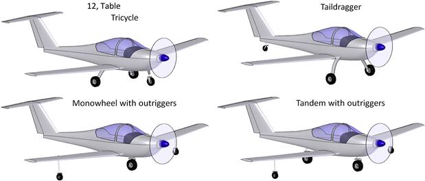
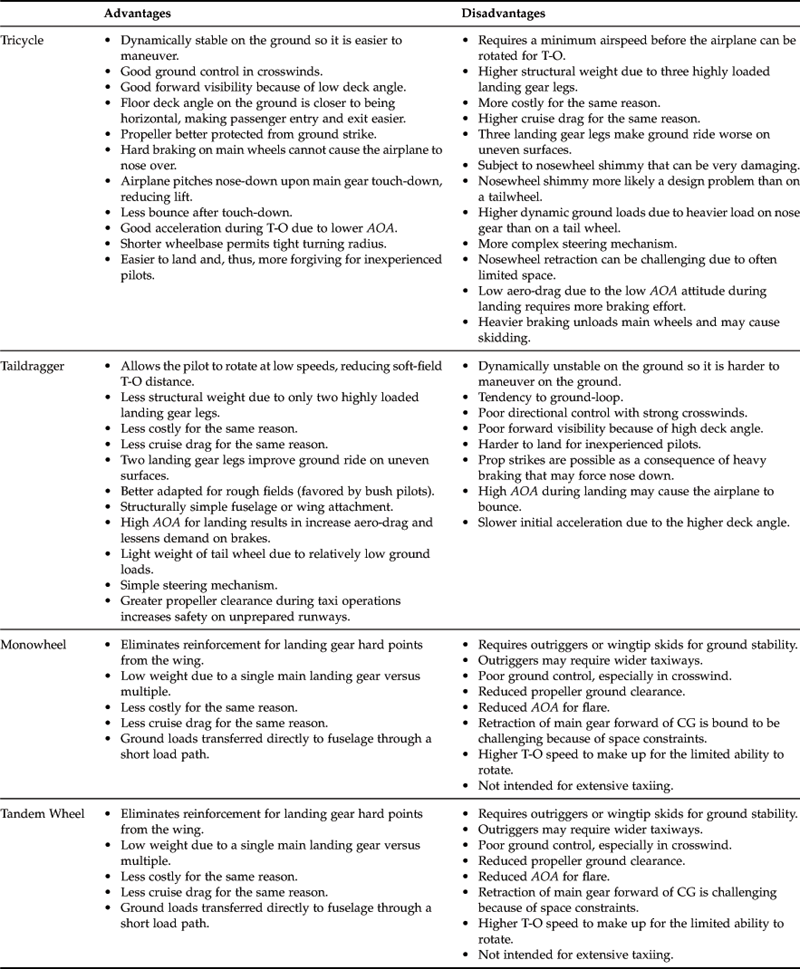
To help with the decision let’s consider the advantages and disadvantages of the above landing gear arrangements. Pazmany [1, p. 21] presents a number of pros and cons that apply to the configurations, some of which are presented in Table 13-1.
13.1.3 Landing Gear Design Checklist
Since the function of the landing gear is one of the most important in the entire aircraft, it is reasonable to list a number of features that the designer should be aware of and that influence a well-designed system.
Positioning
The main and auxiliary landing gears (nosewheel, tail wheel, etc.) must be properly positioned with respect to the CG to reduce the risk of ground looping, overturning, crosswind canting, tail angle, and to allow the airplane to be maneuvered as needed during the T-O and landing ground run. Methods that address this are presented in the following sections:
Section 13.3.1, Geometric layout of the tricycle landing gear
Section 13.3.2, Geometric layout of the taildragger landing gear
Section 13.3.3, Geometric layout of the monowheel landing gear with outriggers
The designer should keep in mind that an efficient structure places stout structural elements near the hardpoints for the landing gear so extra support structure will not be called for.
Ground Clearance
A well-designed landing gear provides adequate clearance between the ground and all other parts of the airplane, even in the worst combination of flat tire and deflated oleo-pneumatic shock absorber. This means propeller tips, nacelles, wingtips, deflected flaps, and so on. A tailskid or bumper should be installed to prevent damage to the airplane from a tail strike.
Landing Gear Component Vendors
Table 13-2 lists a few companies that manufacture and sell components for landing gear.

Tires and Tire Inflation Pressure
The inflation pressure should be selected based on the weight of the aircraft, number of tires, and the bearing capability of the airfield from which the airplane will be operated.
Nosewheel tire pressure should be based on allowable dynamic loads as follows:
Main gear tire should allow for 25% growth in aircraft gross weight. The main gear tire load rating should be based on maximum gross weight and adverse CG location. Forged aluminum-alloy wheels are recommended.
Landing Impact and Braking
The landing gear is required by applicable regulations to react a number of landing scenarios. For GA aircraft, the applicable landing gear loads are stipulated by 14 CFR 23.471 to 23.511. For seaplanes, the hull landing loads are stipulated in 14 CFR 23.521 to 23.562. For land planes, there are individual requirements for landing on the main gear only, three-point landing, and side impact loads. The magnitude of these loads is very high and they are reacted as point loads in the airframe. In addition to the impact forces, the landing gear should provide good damping characteristics and should permit the aircraft to taxi over uneven ground without transmitting excessive shocks to the airframe. The airplane should possess a good, reliable, and safe braking system so that it can handle all braking conditions. It should offer a parking brake that can hold the airplane at gross weight on a 1:10 gradient slope or on a level runway with maximum T-O power applied on one engine. Anti-skid brakes are recommended.
13.2 Tires, Wheels, and Brakes
This section presents some important concepts to keep in mind when designing the layout of the landing gear. Concepts to be cognizant of include landing gear configuration, wheelbase, wheel track, and turning radius.
13.2.1 Important Dimensions and Concepts for Landing Gear Design
Figure 13-2 shows important concepts and dimensions used when discussing landing gear arrangement. The tail wheel spindle axis angle, ϕ, should be inclined forward by some 5°. The tail wheel trail should be 1/10th of the wheel’s diameter. When deflected, the tail wheel shock absorber should place the wheel axle inside the shaded area.
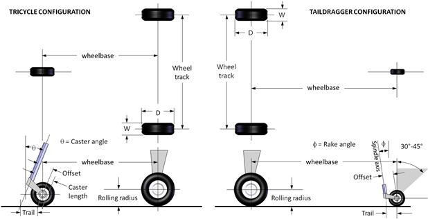
FIGURE 13-2 Important geometric definitions for a tricycle landing gear arrangement. (Based on Ref. [1])
Turning Radius
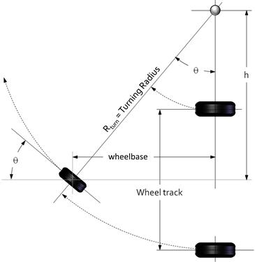
For maneuvering on the ground, in particular when turning into position on a narrow runway, the turning radius is a very important feature in aircraft ground operation. Figure 13-3 shows how the turning radius for a given rotation of the nose landing gear can be determined. The distance h denotes the location of the center of turn and can be calculated using:
Equation (13-2) below allows the turning radius to be calculated, knowing only the wheelbase and the turning angle of the nose gear.
Some aircraft are capable of turning on a dime, literally, by enabling a large enough nose gear turning angle. This requires the nose gear to be capable of turning at least:
![]() (13-3)
(13-3)
Tire Footprint
A tire in contact with the ground will flatten slightly on the bottom so its contact area resembles that of an ellipse (see Figure 13-4). The weight, F, supported by the tire is distributed over this area, generating an average pressure, P, on the area which amounts to:
![]() (13-4)
(13-4)
The higher the pressure inside the tire, the less are the values of a and b. High-pressure tires supporting large loads may cause rutting damage to the runway. On soft enough ground, the tire may sink, which explains why high-floatation tires (so-called “Tundra tires”) have both a large diameter and low internal pressure. Note that the dimension a is usually taken to be 85% of the distance c.
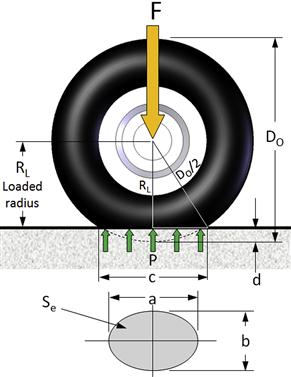
FIGURE 13-4 Tire footprint. (Based on Ref. [1])
Note that the compression of the tire increases the internal pressure due to the reduction of internal volume. The unloaded pressure is therefore always lower than the loaded one. Inflation pressure reported by manufacturers refers to the unloaded tire at standard S-L temperature. Typically, when the tire is loaded to the rated load, the pressure will be approximately 4% higher than the rated pressure. Tires should always be allowed to cool for at least an hour before checking the pressure.
Equation (13-4) can be used to estimate the required internal pressure for a tire if the allowable ground pressure limits are known for a particular runway or taxiways. Effectively, P equals the internal tire pressure.
Manufacturers’ data, such as that of Ref. 2, tabulates the loaded radius, RL, enabling the estimation of the dimension a in Figure 13-4. The first step is relating it to the distance c as shown below:
![]()
The value of a is usually about 85% of c. Therefore, the dimension can be calculated as follows:
![]() (13-5)
(13-5)
Castering Nose and Tail Wheels
The use of castering nose landing gear and tail wheels in taildragger aircraft is a common solution for steerable landing gear in many light GA aircraft. The steering is usually implemented using differential braking, i.e. the pilot steps on the left or right rudder pedals to generate braking in the corresponding main wheel, which turns the aircraft on the ground.
The most common problem with castering landing gear is shimmy, which is a violent oscillation that is a function of speed and the inertia characteristics of the landing gear. Shimmy can begin when the aircraft moves over uneven ground, and even due to worn tires or landing gear parts. It ranges from a simple wobble to an oscillation so violent it literally breaks the landing gear off the airplane. For this reason, castering landing gear is sometimes equipped with a small device called a shimmy damper, which most often is a small cylinder filled with hydraulic fluid that has a piston inside that connects to the movable (rotational) part of the landing gear.
Several configurations are shown in Figure 13-5. Their properties are shown in Table 13-3.

FIGURE 13-5 Five common styles of castering-wheel configurations used for nose and tail wheels. NLG = nose landing gear, TAIL = taildragger, tM = mechanical trail. (Based on Ref. [1])

13.2.2 Retractable Landing Gear
The advent of retractable landing gear was an important element in the evolution of aircraft. It allowed substantial reduction in drag and increase in cruising speed, making it a very attractive option for increasingly efficient aircraft. However, there were drawbacks, although not compelling enough to suppress its use. Not only were there challenges in functionality and failure mechanism, a new type of accident reared its ugly head: landings with perfectly operational landing gear retracted.
There are many elements that make the retraction and extension of retractable landing gear the most critical phase in its operation. Among them is the reliability of locking and unlocking of the extended gear mechanism, as well as the up-locking and release when retracted. This is compounded by the fact that the landing gear is often operated in severe environments, where it gets exposed to mud and ice. It is generally recommended that the actuation mechanism, doors, and support structure should be designed to allow actuation at gross weight and 1.6VS1 or higher. Some aircraft, like the high-flying Learjet business jets, allow the landing gear to be partially extended at even high airspeeds to provide additional drag in an emergency descent [3]. Actuation air loads remain one of the most serious challenges to retraction or extension and can easily exceed the capacity of the actuation mechanism. As mentioned before, partially extended retractable landing gear for fast and high-flying aircraft should be designed to also act as an emergency speed brake. If not possible, the landing gear mechanism should be designed to withstand at least 0.67VC. The time to retract and extend should be less than 10 and 15 seconds respectively [4].
In order to reap the benefit of retractable landing gear it should be stowed under aerodynamically smooth fairings. It also requires an emergency actuation system to allow the pilot to deploy it manually, should the normal actuation mechanism fail. The design is further complicated by the installation of a braking system on the main landing gear or steering mechanism for the nose gear. The design of retractable landing gear should be left to experts, as there are a number of pitfalls for the novice designer. For instance, retraction and deployment loads during transit are hard to predict accurately. These can be surprisingly large, making it impossible for the specified hydraulic mechanism to perform its duty. One possible consequence is the inability to extend the landing gear fully after a successful retraction. This explains why maiden flights are generally made with the landing gear locked in its extended position. Not much needs to be said about the consequences for a development program if the landing gear cannot be extended and the pilot must opt for a belly landing during the first flight.
The kinematics of landing gear retraction and extension is a challenging task, which is best understood by considering the massive landing loads that must be reacted by a compact frame that must repeatedly and effortlessly fold into and out of a small container (the wheel well). The complexity of the system becomes evident in the design of some aircraft, which feature landing gear doors that open temporarily, just to allow the landing gear to pass through, and then close again – not once, but tens of thousands of times. It takes foresight and engineering experience to design a reliable system like that. While this section presents methods to allow the most important geometric details of the landing gear to be designed, the various retraction kinematics are beyond the scope of this text. References 1, 4, and 5 are good resources for general design of landing gear.
Additionally, the size of the internal volume required to house the retracted gear must be kept in mind when sizing the OML. A potential mistake is to find out after substantial analysis has been completed that the wheel wells penetrate the cabin or engine compartment, requiring time-consuming revisions.1 The retraction system should feature an emergency extension system that is independent of the primary system and should not use hand-pumping or cranking by the pilot. The up-locking of retractable landing gear should not use gear door locks and allow an override emergency release. Failure of electric locking systems should never prevent the emergency deployment of the landing gear. Mechanical sequencing (e.g. special landing gear door opening before the landing gear is retracted and the closing after retraction) should be minimized. Niu [5] provides a number of other requirements essential for the detailed design of retractable landing gear.
Figure 13-6 shows a number of so-called ‘stick’ diagrams. These are helpful when visualizing the kinematics of retractable landing gear. The images show the landing gear in its unloaded configuration (in the air) and do not reveal ground deflection. Black nodes represent immovable joints, while white ones are movable. An immovable joint only allows rotation about a fixed point. A movable joint allows rotation and translation. Note that an immovable joint that appears on top of a retracted wheel simply implies an offset hard point.

13.2.3 Types and Sizes of Tires, Wheels and Brakes
The selection of tires for the airplane involves the determination of the type of tire, tire size, wheel, and brakes. This section presents information to help the designer in this matter.
Tire Types
Of the number of standard tire designations used for aircraft, the ones presented in this book are based on definition by the Tire and Rim Association (TRA), which is the technical standardizing body of tires and rims in the USA. TRA designations for common tires are shown in Table 13-4. Note that the Three Part Type designation is the modern system. The designer of certified GA aircraft will pick the Three Part Type designation, whereas the designer of homebuilt aircraft can resort to other types of tires.
TABLE 13-4
Contemporary Types of Tires for Aircraft [2]

KGS stands for knots ground speed. See Chapter 16, Performance – introduction for more details. Note that the ground speeds shown refer to the maximums – the tire can always be used at a lower ground speed.
Inflation Pressure
The tire maintains its shape as a consequence of the inflation pressure. Tires are very flexible in bending but have very limited extension (or stretch). As the tire reacts loads its cross-section flexes and a side force will be generated on the flange of the rim. The tire is designed to operate at an approximately 32–35% deflection under static load, but this means it will bottom out at around 3× the static load. Shock absorbers are designed to bottom out at 3× the static load as well, and are intended to do so before the tire1. Table 13-5 shows ranges of pressure for various applications.
TABLE 13-5
Range of Inflation Pressures for Typical Aircraft
| Pressure, psi | Comment |
| <40 | Recommended for unimproved, low-strength and uneven runways. A high-AR tire and low pressure offers great impact cushioning, minimizes surface rutting, and improves the durability of the treads and tire in general. This is the pressure range for the typical automobile tire. |
| 40–75 | Used for tires expected to operate off improved runways. |
| 75–125 | Intended for high-performance aircraft operating off asphalt and concrete runways only. The higher pressure allows for a smaller and lighter tire, which is helpful for reduced aerodynamic drag and stowing volume. |
| >125 | Generally not used for GA aircraft. |
Tire Geometry
The following parameters are important when discussing tires (refer to Figure 13-7):
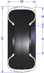
Ensure there is no confusion with the AR of a wing. A low tire AR means it is wider than it is high. Such tires are intended for high speeds on smooth surfaces. High-AR tires are meant for rough field operations that call for improved floatation.
| Type III have AR ranging from: | 0.85 to 1.00 |
| Type VII have AR ranging from: | 0.77 to 0.90 |
| Type VIII have AR ranging from: | 0.65–0.77 |
| Three Part Type have AR ranging from: | 0.73 to 0.92 |
An LR of 1.5 to 2.0 is considered low, while 2.0 to 2.5 is desirable [1].
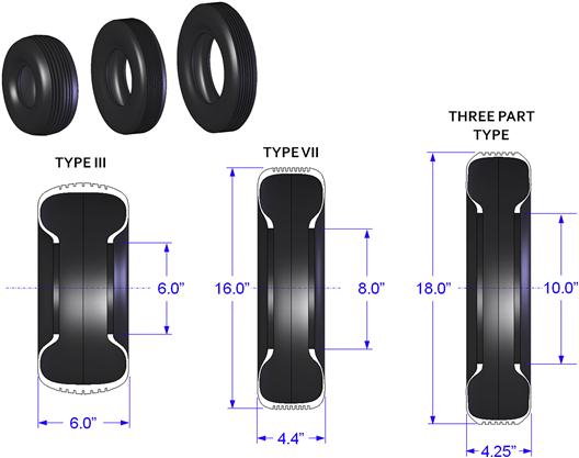
Tire Sizes
Unfortunately, when it comes to specifying tire sizes there is no one standard, but rather several that have evolved since the inception of tire standardization in 1903. This results in several choices at the disposal of the designer, although focusing on the Three Part Type is recommended for modern aircraft design. The TRA type tires shown in Table 13-4 have the sizing designation shown in Table 13-6. Figure 13-8 shows schematics of the three most common types, Type III, VII, and the Three Part Type.
TABLE 13-6
Examples of Dimension Designation for Various Types of Tires for Aircraft
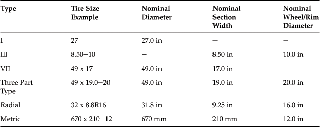
(Based on Ref. [2].)
Selection of Tire Sizes
The first step is to download a document like Ref. [2], which features an excellent selection guide in Section 4 – Data Section – Tires. The document lists tires by type and rated speed, load, inflation pressure, braking load, and bottoming load. It is an ideal resource to pick a potential tire during the conceptual and preliminary design phase. It can be downloaded free of charge from: www.goodyearaviation.com/resources/. Also, note that for the certification of GA aircraft, the tire selection is bound by 14 CFR 23.733 Tires.
It is problematic that Type III do not explicitly specify the nominal diameter of the tire. For specific dimensions refer to Ref. 2.
Main wheel tires: select main landing gear tires in accordance with the following guidelines:
(1) Account for a growth in the weight of the airplane (assuming it is intended to become a successful production). It is customary to assume a weight 25% greater than the initial gross weight. History shows that airplanes almost always increase their weight as new models are introduced in response to the desire for added capabilities. For this reason, selecting a larger tire now can avoid costly re-engineering later.
(2) Selection should be based on the load caused by the aft-most CG location for tricycle, and most-forward CG location for taildraggers.
(3) Assume the most severe load-speed-time history during normal operation. This means determining the most adverse combination of high elevation and high ambient temperature take-off or landing. Low-density atmospheric conditions lead to higher ground speeds and this is critical to the tire selection process.
Nosewheel tires: select nose landing gear tires in accordance with the following guidelines:
(1) As with the main landing gear tire, account for a growth in the weight of the airplane by assuming a 25% weight growth.
(2) Estimate static and dynamic braking load on the tire. Consider 14 CFR 23.493 Braked Roll Conditions in this matter.
Tail wheel and outrigger wheels: for smaller aircraft, the tail wheel and outrigger wheels are solid rubber. For larger aircraft, inflated tires are used and can be selected using a similar approach to the above. In the absence of rational analysis, if the outrigger wheels are intended to support landing impact, the attachment structure should be capable of supporting a vertical and side load amounting to 1/2 g. The wheel can then be selected based on the resulting load. For example, an airplane with an outrigger and 1000 lbf gross weight would be reinforced to react 500 lbf acting at the tire. This side load requirement is in accordance with 14 CFR 23.485 Side Load Conditions, although the regulations do not specifically address outrigger configuration. There is no set rule in outrigger structure. Aircraft like the Fournier RF-1 and RF-3 use outriggers not capable of reacting the above load, albeit sufficient to support taxi loads. The Fournier RF-2 does not even use wheels, but rather a wire loop, each end of which is mounted to the wing structure.
Wheels
The modern wheel is usually made from forged aluminum or magnesium alloy. Aluminum wheels are heavier, but are less expensive and have better corrosion resistance. Both are equal in robustness and have the same performance rating.
Wheels usually consist of two halves that are joined together by bolts (see Figure 13-9). Some modern designs are of a single-piece configuration that is easier to manufacture and maintain. They feature special lock-rings to provide the necessary lip for the tire.2 The wheel contains tapered roller bearings that are a press fit into a space called the bearing housing. They are kept in place by spring-fit snap rings. Brake discs are often attached to the wheels using the fasteners that hold the two halves together.
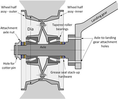
There are three common sizes of wheels for small aircraft: 5′′, 6′′, and 7′′ diameter. The diameter (Dia) is measured between the wheel shelves as shown in Figure 13-9.
Brakes
The brakes must provide the airplane with a means to: stop the aircraft after landing or an aborted take-off; keep the airplane at rest at full power (this means the critical engine only for a multi-engine aircraft); allow the airplane to be steered via differential braking or appropriate slow-downs during taxiing; and park. The brakes are not expected to retain the aircraft with the wheels locked should there be enough thrust to move the aircraft. A simplified schematic of the brake system in a light aircraft is shown in Figure 13-10.
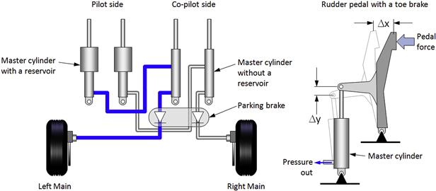
FIGURE 13-10 A schematic of a brake system for a small aircraft. It is recommended that Δy = ½ Δx. (Based on Ref. [6])
There are two common kinds of brakes: drum brakes and disc brakes. Drum brakes usually reside inside the wheel, which reduces their frontal area and, if mounted on retractable landing gear, makes them a possible solution for space-claim issues in thin wings. Disc brakes have superior performance, are lighter, and easier to maintain.
The application of brakes generates considerable heat through friction. The amount of heat depends on factors such as the weight of the vehicle being stopped, the speed at which braking is applied, the effectiveness of the conversion of friction into heat, and the friction area of the brakes. This is where the difference between drums and discs become apparent. Drum brakes dissipate heat far less effectively than disc brakes. Since the brake is contained inside the wheel the result is inferior heat transfer from the drum and if too much heat is generated the braking capacity is lost (“fading”) just when it is needed the most. In contrast, disc brakes reside on the outside of the wheel and are directly exposed to air, in addition to featuring calipers with two braking pads on each side of the disc (and sometimes multiple discs). Direct exposure to air leads to superior cooling and more effective braking under demanding conditions.
Manufacturers recommend that wheels and brakes be selected together. These should be selected in accordance with the following guidelines:
(1) Determine the static load on each wheel. Select wheels whose rating matches or exceeds this value.
(2) The selection of brakes for GA aircraft is bound by 14 CFR 23.735 Brakes. This requires the brakes to have the capacity to absorb the kinetic energy of the aircraft based on one of two methods: conservative rational analysis and, in the absence of such analysis, on the following formula:
![]() (13-6)
(13-6)
where
Equation (13-6) yields the kinetic energy per brake and this value must be specified when contacting brake manufacturers.
Derivation of Equation (13-6)
For VS0 in ft/s or m/s and m in slugs or kg, the kinetic energy is given by:
![]()
The above regulatory paragraph assumed VS0 in KTAS and W in lbf. Therefore,
![]()
QED
Other Useful Information
Aircraft tires are designed such that the internal tensile forces in each fabric layer are uniform when unloaded. When deflected, this force will vary from higher in the outer plies to lower in the inner ones. This variation generates shear stresses in the tire that must not be exceeded. Exceeding this is possible if the tire is under-inflated or over-loaded. This will cause a large deflection that leads to heat build-up which can cause ply separation and rapidly decrease the durability of the tire. It will also cause an uneven wearing of the tread and deterioration of the shoulder, in addition to possible damage to the sidewall of the tire during high impacts (landing). Excessive inflation pressure can also be detrimental due to uneven tread wear and reduced braking effectiveness, as well as making the tire more susceptible to damage by foreign objects.
Tires can withstand reasonably high temperatures, with typical maximum operational limits being a surface temperature that exceeds 225 °F (107 °C) or brake heat reaching a temperature of 300 °F (149 °C). Such a temperature can result from excessive braking after a high-speed landing.
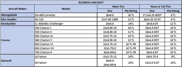
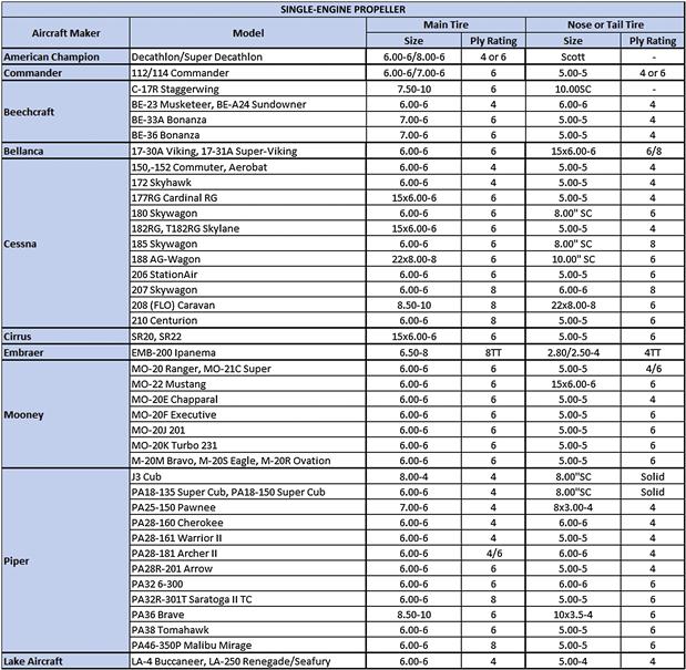
Finally, when selecting wheels and tires, it can be helpful to know the types of tires used for existing fleets of aircraft. Tables 13-7, 13-8, and 13-9 provide such information for selected aircraft of various classes. The reader is directed toward Ref. 2 for more details.

13.2.4 Types of Landing Gear Legs
One of the most important capabilities of any landing gear is how it absorbs the landing impact load. For GA aircraft the most common way to accomplish this is through the use of leaf-springs, rubber doughnuts, rubber bungees, coiled steel springs, and oleo-pneumatic shock absorbers. The first three are depicted in Figure 13-11, showing typical deflection at impact (denoted by ‘d’). The primary advantage of such landing gear is its simplicity and relative light weight. However, their shock absorption efficiency is less than ideal. To understand why, consider the graphs of Figure 13-12. Then a few words about shock absorption are necessary.
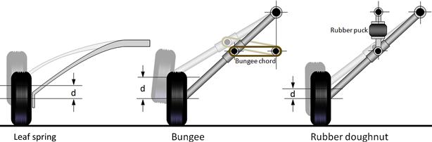
FIGURE 13-11 A schematic of typical leaf-spring, bungee, and rubber doughnut shock absorbers. The dimension ‘d’ is the deflection of the gear, which is indicative of the efficiency of the landing gear shock absorption.
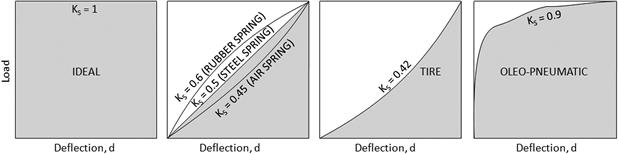
FIGURE 13-12 Load versus deflection graphs showing what is meant by shock absorption efficiency. (Based on Ref. [1])
The purpose of a shock absorber is to help bring some initial speed of some mass to zero through deceleration over a given distance. Ideally, this deceleration is achieved through the force acting on the absorber, which changes from an initial zero force, to some maximum load just as the speed reaches zero. In airplanes, it serves to bring the rate-of-descent to zero. Intuition holds that if this deceleration takes place over a long distance, then, from the standpoint of the occupants, the landing will be soft and void of a “shock.” Unfortunately, we do not have the luxury of a long distance. The vertical speed, which ranges from 10 to 20 ft/s, must be brought to zero in only a few inches. If a very flexible spring is used, then it will bottom out before the vertical speed reaches zero – and we are in for a very hard shock. If the landing gear is rigid – well, we are also in for a hard shock. The solution to this is to provide some spring action that is neither too flexible nor to stiff. Figure 13-12 shows this in action.
By definition, the ideal shock absorber has 100% efficiency because it achieves the maximum deceleration in the minimum distance – the comfort of the ride has no bearing on this value. This is denoted by the constant KS in Figure 13-12, which shows that if KS = 1, then the entire landing load will be reacted without deflection. A steel spring obeys Hooke’s law and can be sized to react the impact over the available distance with 50% efficiency (KS = 0.5). It will improve the ride, but demands much greater available distance for the deceleration to take place. A tire is even less efficient, with efficiency KS = 0.39 to 0.47 (per Ref. [1]). However, the oleo-pneumatic strut is one of the most efficient means to slow down the aircraft. The graph shows it will react most of the landing load over a relatively short distance, and then the remaining load will be reacted while providing a much more comfortable ride for the occupants.
The landing gear comes in a wide variety of shapes and sizes; volumes could be written about the pros and cons of each. Here, however, in the interest of space, only the four common types shown in Figure 13-13 will be presented. These are the leaf-spring steel (or composite) main landing gear, (A); oleo-pneumatic strut retractable main landing gear, (B); oleo-pneumatic retractable trailing-link main landing gear, (C); and a steerable oleo-pneumatic strut nose landing gear, (D).

FIGURE 13-13 Schematics of common types of landing gear for small aircraft. (A) a leaf-spring steel (or composite) main landing gear; (B) an oleo-strut retractable main landing gear; (C) an oleo-strut retractable trailing-link main landing gear; and (D) a steerable oleo-strut nose landing gear.
It should be stressed that there are many other ways to absorb the landing impact. Many are presented in Refs 1, 4, and 5, not to mention Ref. [7], which presents, not surprisingly, incredibly original landing gear designs devised by German engineers during World War II. It is a good source for anyone looking for interesting ideas for landing gear. However, those presented in Figure 13-13 represent the most common ways this is accomplished for the modern GA aircraft.
Leaf-spring Landing Gear (A)
The leaf-spring landing gear, as the name implies, consists of a relatively flat but stiff cantilever beam that reacts landing loads in bending. The primary advantage of such landing gear is that it is inexpensive, stout, durable, and is relatively easy to mount to an airplane. It really represents the simplest form of the landing gear. The leaf-spring landing gear is generally used as the main landing gear. Its relatively low thickness-to-chord ratio renders it a relatively low-drag external structure, although the wheels, tires, and braking calipers generate substantial drag and should be covered using a wheel fairing. The primary drawbacks are high reaction loads in the airframe, as the spring beam tends to have a large moment arm. Also, the landing gear does not lend itself well to a retractable configuration. Some Cessna aircraft feature retractable cantilevered landing gear that resembles leaf-spring gear, but really consists of tubular geometry. The leaf-spring has limited structural damping, but works well because of the damping provided by the scrubbing motion of the tires. It has a poor efficiency as a shock absorber, something remedied by the scrubbing motion as well. To the best knowledge of the author, the largest aircraft to currently use a leaf-spring landing gear is the de Havilland of Canada DHC-6 Twin Otter, with a maximum gross weight of 12,500 lbf.
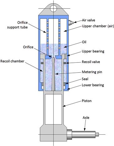
Oleo-pneumatic Landing Gear (B, C, D)
(B), (C) and (D) in Figure 13-13 are types of landing gear that use a mechanical oleo-pneumatic shock absorber of the type shown in Figure 13-14. Such a shock absorber initially presses the oil against air or nitrogen, while dissipating the impact energy by forcing the oil to flow through a number of recoil orifices. This allows the shock from the landing impact to be reacted initially with a short deflection, and then a larger one as the oil seeps back into its chamber. Reference 4 provides methods to size oleo-pneumatic struts.
Oleo-pneumatic Trailing-link Landing Gear (C)
The oleo-pneumatic trailing-link landing gear has become a popular option in many aircraft due to the superior ride quality it offers on uneven ground. This is possible as the mechanism allows for much larger deflection of the wheel and tire assembly than is possible when mounted directly to the strut. The drawback of the trailing-link landing gear is its greater weight and cost. It also requires a larger internal volume to stow.
Various Landing Gear Issues – Shimmy
Shimmy is a violent dynamic instability that occurs, primarily in free-castering landing gear, due to unbalancing of the forces that act on the members of the trailing link. This is a frequent issue that can be violent enough to break off the nose landing gear. It is therefore of substantial importance to the manufacturer and operator alike. The aircraft designer should be aware of it and possible solutions (shimmy dampers, high-friction castering, geometric relations, mass balancing, and so on).
Various Landing Gear Issues – Whistling
Whistling is a phenomenon in which the complex geometry of a landing gear exposed to the airflow in flight generates a high-pitched audible sound. One aircraft that repeatedly generates this sound is the Piper PA-28 Arrow with its retractable landing gear extended. There is not much that can be done to eliminate the whistling. The author is not aware of any particular studies that have been performed to evaluate the source either of the sound or of potential solutions.
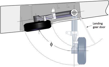
Various Landing Gear Issues – Non-linear Loads During Retraction and Deployment
During the retraction or deployment of landing gear, the actuation system (linkages and hydraulic actuator) undergo variable loading. An actuator capable of brisk retraction or extension during ground tests (when airspeed in zero) may turn out to be grossly undersized when air loads compound the inertia loads. For instance, consider the retraction of a main landing gear into a wing, exemplified in Figure 13-15. As the gear rotates into the wheel well, the air loads acting on the landing gear door (whose effect is attenuated by the complex flow field around the landing gear leg and wheel) may overload the actuator unexpectedly (well, only prior to you reading this) so the gear is stuck in a partially retracted position. It might get stuck at a ϕ ranging from 30° to 60°. This may cause a serious problem in a flight test if the actuator is undersized – it should always be oversized so it has adequate power to power the gear. The test pilot should be ready with a contingency plan – for instance, try retraction just above stalling speed.
13.2.5 Reaction of Landing Gear Forces
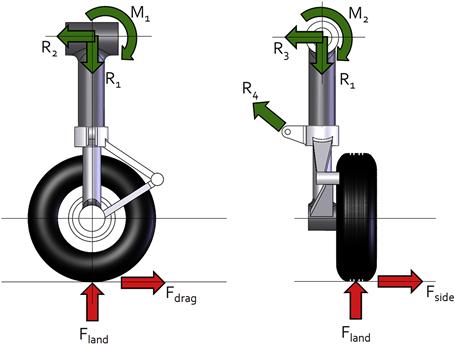
The landing gear force matrix consists of three force components: a vertical force, Fland, drag force, Fdrag, and side force, Fside. The determination of the magnitude of these loads is done by two means: regulatory or rational analysis. The regulatory loads comprise a “cookbook” style calculation that is designed to be very conservative. Its primary advantage (some would claim the only advantage) is that is saves a lot of analysis time required to complete a rational analysis. However, it can be argued that the resulting aircraft is heavier than it need be. For GA aircraft, 14 CFR 23.471 through 23.511 provide the necessary guidance to estimate all necessary loads for land-based aircraft to show compliance with the regulations.
Figure 13-16 shows a balanced free-body diagram depicting how the landing loads are reacted in a typical landing gear design. The landing gear reaction loads (R1 through R4 and M1 and M2) must be reacted at specific hard points, in either the wing or the fuselage. These, in turn, require a local reinforcement to transfer the reaction loads into the airframe. Local reinforcement is another way of saying “added structural weight.” Of course, Nature leaves no choice to the designer – the only countermeasure is to try and minimize this weight by designing effective load paths.
13.2.6 Comparing the Ground Characteristics of Taildragger and Tricycle Landing Gear
One of the most important differences between a taildragger and tricycle landing gear is their handling on the ground. The taildragger is dynamically unstable, while the tricycle is dynamically stable. To see why, consider Figure 13-17. It shows a taildragger configuration, with a wheel track wt in a straight and yawed configuration. Note that the figure shows the bottom of the airplane, so the left wing is to the right and vice versa. In this situation, the ground friction of each main gear (FR and FL) tire creates an equal and opposite moment about the CG.
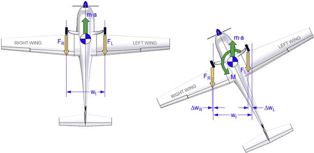
In the right image the aircraft is shown yawing to the right. This changes the moment arms of the two ground reactions. The right one (FR) is increased by a distance ΔwR, resulting in an increased destabilizing moment. The left reaction (FL) is decreased by a distance ΔwL, yielding a reduced stabilizing moment. The sum of the two is a destabilizing moment that promotes an even greater yawing tendency. Consequently, the configuration will be inherently unstable.
The opposite holds for a tricycle landing gear and this is shown in Figure 13-18. In the left image, the ground friction of the main gear creates an equal and opposite moment about the CG, just like it did for the taildragger. Note the addition of the reaction of the nose landing gear, FN. In the right image, the aircraft is yawing to the right. As before, the ground friction from the right main and nose tires generates a destabilizing moment. However, this time they act along a decreasing moment arm. The ground friction of the left tire, on the other hand, is stabilizing and it acts along a moment arm that increases with the yaw angle. Consequently, the stabilizing moment increases with yaw angle, rendering the configuration inherently stable.
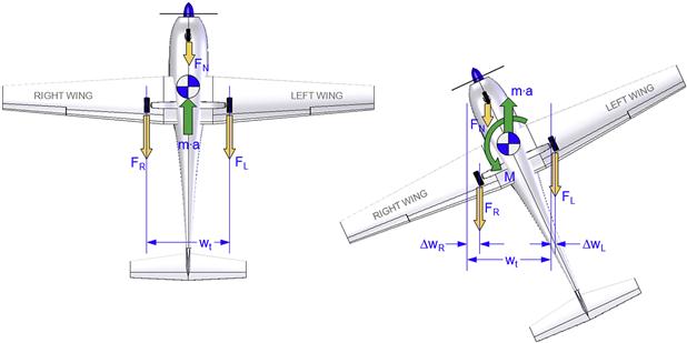
In conclusion, the tricycle configuration is safer than the taildragger and, thus, is selected for most airplanes. In particular, primary trainers and commercial aircraft should always feature this configuration. However, as has already been discussed in Table 13-1, the taildragger configuration is a better choice for light aircraft that take-off and land on poorly prepared runways (bushplanes).
13.3 Geometric Layout of the Landing Gear
This section presents methods that help to accurately lay out the landing gear geometry for tricycle, taildragger, and monowheel configurations. Additionally, methods to evaluate loads on the landing gear will be developed.
13.3.1 Geometric Layout of the Tricycle Landing Gear
If a decision is made to proceed with a tricycle landing gear, the next step is to define the layout of its geometry. The tricycle landing gear can be laid out as presented below; however, first the following must be completed:
(1) A side view of the design in a cruise attitude. Draw the mean geometric chord (MGC) on the side view.
Refer to Figure 13-19 for Steps 1 and 2.

Step 1
Draw the forward CG limit.
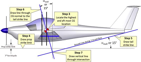
Step 3
Determine the highest vertical CG location at the aft CG limit and plot on the diagram as shown. This position is the most critical as it is the first point to cross the vertical line drawn in Step 7. If that happens, the plane will fall on its tail.
Step 4
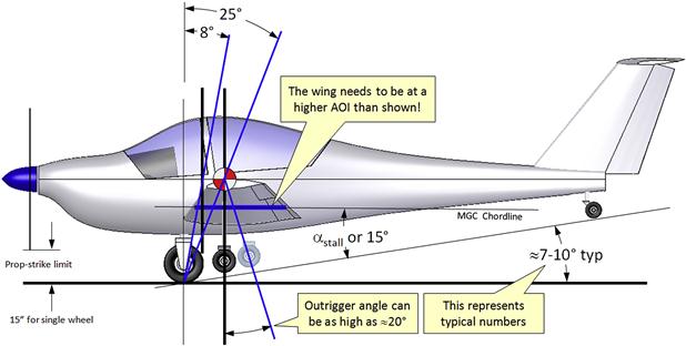
Draw the prop-strike limit as shown, ensuring it is parallel to the ground plane. This is as close to the ground the propeller should get under most adverse conditions, such as with a flat nose gear tire. The limit per 14 CFR 23.925(a) is 7 inches.
Step 5
Draw the tail-strike line as shown, ensuring it is at an angle of αstall in the clean configuration (because this is the highest angle) up to a maximum value (recommended) of 15°. The tail strike line is also the ground line.
Step 6
Draw a line through the CG perpendicular to the tail-strike line. This is where the contact point of the tire should be, at static deflection of 1 g load. IMPORTANT: This is the static deflection of 1 g load. The landing gear will drop below the tail strike line once it is off the ground.
Step 7
Draw a vertical line through the intersection of the tail-strike line and the normal to it. It should form the same angle as the tail-strike line does to the horizontal. If done correctly, the three lines should all intersect at the same point.
Refer to Figure 13-21 for Steps 8 and 9.
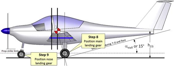
Step 8
Position the main landing gear such the contact point of the wheel is at the intersection of the three lines as shown in Figure 13-21. If practical, align the main landing gear leg along the vertical line.
Step 9
Position the nose landing gear so it carries no more than 20% of the aircraft weight when the CG is at the forward limit, and no less than 10% when the CG is at the aft limit. Too much nose gear load will simply make it harder to rotate the airplane for lift-off. Too light a load will make steering the aircraft harder because of reduced ground friction. A light nose gear load can also promote “porpoising” on the ground.
A few more steps are required to properly position the landing gear.
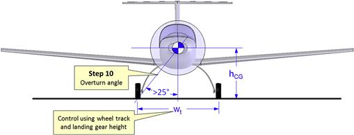
Overturn Angle
The following steps are intended to verify that the wheel track is wide enough to provide lateral stability when taxiing and turning a corner. Since the CG is located distance hCG above the ground, the centrifugal force it generates as the airplane turns will result in an overturning moment that can roll the airplane on the wing to the outside of the trajectory. To minimize the risk of this, the designer should check that the combination of wheel track and hCG will not cause this to take place. As a rule of thumb, the closer to the ground the CG is, the better will be the lateral stability of the airplane. The farther forward the CG, the less is the lateral stability.
Refer to Figure 13-22 for Steps 10 through 14.
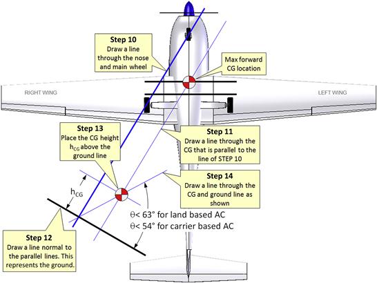
Step 10
Draw a line through the center of the contact points of the nose and the left or right main landing gear as shown in Figure 13-22. Here, the right landing gear has been chosen (note that we are looking up on the bottom of the airplane, so the right wing appears to the left).
Step 11
Draw a line through the CG that is parallel to the line drawn in Step 10. For clarity, draw both lines far enough from the airplane to allow additional lines to be marked with ease.
Step 12
Draw a line that is perpendicular to the lines drawn in Step 10 and Step 11. This line represents the ground.
Step 13
Place the CG distance hCG above the ground line, along the line drawn in Step 11, as shown in Figure 13-22. Also refer to the definition of the hCG in Figure 13-21.
Step 14
Draw a line that extends from the intersection of the line drawn in Step 10 and the ground line drawn in Step 12, to the CG. This line represents the overturn angle, θ. This angle should be less than 63° for general land-based aircraft and 54° for carrier-based aircraft. If it is larger, then any of the following measures can be taken (provided preceding requirements are not violated):
13.3.2 Geometric Layout of the Taildragger Landing Gear
If a taildragger configuration is to be designed, the next step is the layout of its geometry. The procedure is fundamentally similar, with a couple of exceptions. As before, the following must be completed:
(1) A side view of the design in a cruise (or tail-off-ground T-O) attitude. Draw the mean geometric chord (MGC) on the side view.
Refer to Figure 13-19 for Steps 1 and 2.
Step 1 and 2 are identical to those for the tricycle landing gear.
Refer to Figure 13-23 for Steps 3 through 7.
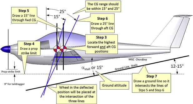
Step 3
Determine the highest vertical CG location at the forward and aft CG limits and plot on the diagram as shown. These two positions are critical to the proper positioning of the main landing gear.
Step 4
Draw the prop-strike limit as shown, ensuring it is parallel to the ground plane. This is as close to the ground as the propeller should get under most adverse conditions, such as with a flat nose gear tire. The limit per 14 CFR 23.925(a) is 9 inches.
Step 5
Draw a line at an incline of 15° that goes through the forward CG location. Note that some references cite 16°, but either one will work just fine.
Step 6
Draw a line at an incline of 25° that goes through the aft CG location. For most aircraft the CG envelope is enclosed between these two lines.
Step 7
Locate the intersection of the lines in Step 5 and Step 6. This is where the contact point of the tire should be, at a static deflection of 1 g load. Draw a line at an incline of 12° to 15° that goes through this intersection, as shown in Figure 13-23. This line represents the ground and should be used to place the tail wheel. Note that the incline of the line shown is 12°. Note that, ideally, the angle of incidence made by the MGC with respect to the ground line should be that of αstall up to a maximum value (recommended) of 15°.
Refer to Figure 13-24 for Steps 8 and 9.
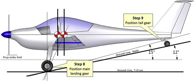
Step 8
Position the main landing gear so the contact point of the wheel is at the intersection of the three lines as shown in Figure 13-24.
Step 9
Position the tail wheel landing gear such it carries no more than 5% of the aircraft weight when the CG is at the forward limit, and no greater than 10% when the CG is at the aft limit. Too much load on the tail wheel will make it harder to raise the airplane during the ground run. Too light a load will make steering and controlling the aircraft in a crosswind harder because of reduced ground friction.
Step 10
It is imperative that the main landing gear wheel track is wide enough to guarantee the airplane is stable while it corners on the ground. Ensure the width between the tires, Wt, is large enough so the overturn angle is 25° or greater (see Figure 13-25).
13.3.3 Geometric Layout of the Monowheel Landing Gear with Outriggers
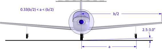
The monowheel landing gear with outriggers is primarily used in motor gliders. Examples of such aircraft include the Scheibe SF-25 Falke; SF-28 Tandem Falke; Fournier RF-1, RF-2, RF-3, RF-4, RF-5; and the Europa XS. The procedure for positioning the main wheel and the outriggers is fundamentally similar to the previous methods, with a couple of exceptions. Important design guidelines are shown in Figure 13-26.
Stinton [8] indicates the ideal spanwise position of the outrigger is at the rolling radius of gyration3 as this will result in a minimum outrigger load in an “outrigger first” landing. Exploring a database of such aircraft shows this methodology is not used in outrigger design in general. Pazmany [1, p. 20] shows that the outrigger distance (a) from the plane of symmetry generally ranges from 33% to 100% of the wing half-span (b/2) (Figure 13-27). Placing the outriggers at the wingtip is not unheard of. For instance, the Rutan Solitaire and the Monnett Monerai both feature outriggers at the wingtip.
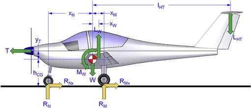
13.3.4 Tricycle Landing Gear Reaction Loads
Figure 13-28 shows loads acting on a tricycle landing gear configuration as it moves at a constant speed during the ground run. We want to determine the reaction loads on the nose and main landing gear, denoted by RN and RM, respectively.
Special Case – Static Loads
For this case V = 0 and T = 0 (note that this makes friction irrelevant as it only affects the aircraft in motion), leading to the following results:
![]() (13-9)
(13-9)
Note that since the location of the CG is used as a reference in this formulation, a question of sign convention might be raised. For instance, in Figure 13-28, should xM have a positive sign and xN a negative sign? What about the forces?
The formulation setup here assumes absolute values of all dimensions and forces. Signs are taken care of in the formulation of both forces and moments. The only exception is the sign of MW, which is typically negative (nose pitch-down). Its sign is the only one that must be accounted for when using the formulation.
Definition of Aerodynamic Loads
The following formulation of the lift and thrust is convenient, as it allows the designer to evaluate the impact of various aerodynamic characteristics on the landing gear reaction forces. For instance, if a spreadsheet has been prepared, the designer can evaluate the airspeed when rotation to lift-off can be achieved, and evaluate design changes to modify it if necessary.
Derivation of Equation (13-7)
Begin by defining the horizontal ground friction force:
![]() (i)
(i)
Sum forces in the vertical (z) direction, such that positive forces act upward:
![]() (ii)
(ii)
This yields the main landing gear reaction force RM:
![]() (iii)
(iii)
Sum moments about the center of gravity (CG), such that nose pitch-up moments are positive (note that the ground friction RMx and RNx are written explicitly as μ(RN + RM)∙hCG):
![]() (iv)
(iv)
Note that typically the value of the wing pitching moment, MW, is negative. Expand and rearrange the RN and RM terms:
![]()
Simplify in terms of RN and RM:
![]()
Inserting Equation (iii) for RM yields:
![]()
Rearrange to combine the term RN yields:
![]()
![]()
Finally, solving for the nose gear reaction force, RN, yields:
![]() (iv)
(iv)
QED
EXAMPLE 13-1
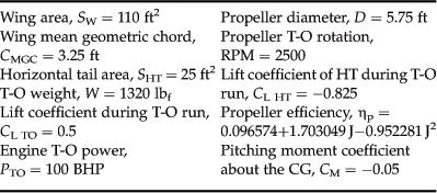
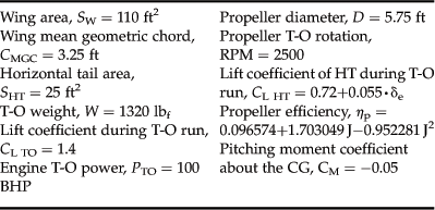
Consider the dimensions of the aircraft in Figure 13-29 and whose pertinent characteristics are listed below. Determine the following:
(a) the static ground reaction loads without engine power;
(b) dynamic ground reaction loads on the NLG and MLG, assuming no rotation at V = 40 KTAS; and
(c) the airspeed at which the pilot can (slowly) rotate the nose of the aircraft to lift off, assuming the constant airspeed formulation.
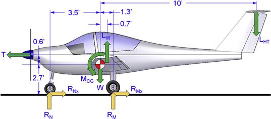
For convenience, assume the propeller efficiency can be described using the function shown in Figure 14-45.
Solution
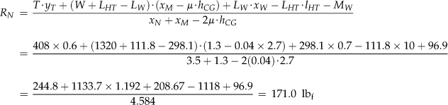
(a) Static ground reaction loads without power:
Nose reaction from Equation (13-9):
![]()
Main landing gear reaction:
![]()
(b) Dynamic ground reaction loads at V = 40 KTAS:
Airspeed in ft/s:
![]()
![]()
![]()
![]()
![]()
![]()
![]()
![]()
Nose landing gear reaction load:
Main landing gear reaction loads (total for both wheels):
![]()
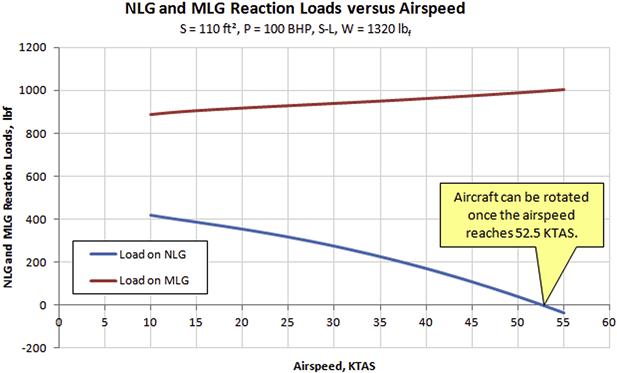
(c) Determine the rotation airspeed:
The rotation airspeed can be determined by calculating the reaction loads for the nose landing gear for a range of airspeeds and then identifying where the NLG reaction load becomes zero. The calculations are easily implemented in a spreadsheet. The calculation shown in Part (b) was implemented for airspeeds ranging from 10 through 55 KTAS using Microsoft Excel. The results have been plotted in Figure 13-30. It is evident from the figure that the airplane will be capable of lifting the nosewheel at around 52.5 KTAS.
It should be pointed out that as soon as the nose landing gear lifts off the runway, the model represented here is no longer valid, because the rotation inevitably means change in AOA. This brings about a significant modification of the flow field, changing the lift coefficients of the wing and HT. However, the method presented here returns a reliable value below and up to the rotation speed.
It is absolutely imperative that the aircraft designer checks the capability of a new design to rotate below VLOF, in particular if the design features a high thrust line. The analysis presented above will reveal whether or not an adequate elevator authority is available.
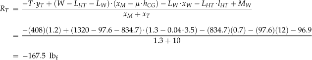
13.3.5 Taildragger Landing Gear Reaction Loads
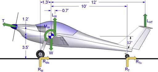
Figure 13-31 shows loads acting on a taildragger landing gear configuration at a constant speed during the ground run, while the tail is still on the ground. We want to determine the reaction loads on the main and tail landing gear, denoted by RM and RT, respectively.
![]() (13-10)
(13-10)
![]() (13-11)
(13-11)
where
LHT = horizontal tail lift, in lbf or N

Special Case – Static Loads
As already discussed in Section 13.3.4, Tricycle landing gear reaction loads, the formulation is set up assuming absolute values of all dimensions and forces. With the exception of MW, the proper signs are taken care of in the formulation of both forces and moments.
Another confusion that might arise is the direction of LHT, shown as pointing downward in Figure 13-31. Strictly speaking the direction of this force, as setup for the derivation below, does not matter. What matters is that the force direction is already defined as positive upward. If the elevator is neutral (as is shown in the figure) the force would actually point upward (in the positive direction). This would cause a tendency to lift the tail off the ground.
Derivation of Equation (13-10)
Begin by defining the horizontal ground friction force:
![]() (i)
(i)
Sum forces in the vertical (z) direction, such that positive forces act upward:
![]() (ii)
(ii)
This yields the main landing gear reaction force RM:
![]() (iii)
(iii)
For simplicity, assume thrust is largely horizontal. Sum moments about the center of gravity (CG), such that nose pitch-up moments are positive:
![]() (iv)
(iv)
Note that typically the value of the wing pitching moment, MW, is negative. Expand and rearrange the RT and RM terms:
![]()
Simplify in terms of RT and RM:
![]()
Inserting Equation (iii) for RM yields:
![]()
Rearrange to combine the term RT yields:
![]()
Finally, solving for the nose gear reaction force, RT, yields
![]() (v)
(v)
EXAMPLE 13-2
Consider the dimensions of the aircraft in Figure 13-29 and whose pertinent characteristics are listed below. Determine the following:
(a) the static ground reaction loads without engine power;
(b) the airspeed at which the tail wheel lifts off the ground for elevator deflection δe = −10°, 0°, +10°, assuming the constant airspeed formulation.
For convenience, assume the propeller efficiency can be described using the function shown in Figure 14-45.
Solution
This way, the tail wheel carries about 11.5% of the gross weight of the aircraft in the static configuration. This is the upper limit of what is advisable for static loads and the designer should consider moving the tail wheel a tad aft, unless other factors make it impossible.
(b) Determine the airspeed at which the tail wheel lifts off the ground for elevator deflection δe = −10°, 0°, +10°:
Note that the HT lift coefficient is given by CL HT = 0.72+0.055∙δe, where the value 0.72 reflects the fact that while the tail is on the ground the HT will be generating a positive lift, i.e. lift that points upward. The elevator deflection, reflected by δe, increases the lift coefficient when the elevator is deflected trailing edge down (TED) and decreases when it is deflected trailing edge up (TEU).
Validation calculation for V = 40 KTAS and δe = 0° (or CL HT = 0.72):
Airspeed in ft/s:
![]()
Dynamic pressure:
![]()
Advance ratio:
![]()
Propeller efficiency:
![]()
Thrust:
![]()
Wing lift:
![]()
HT lift:
![]()
Pitching moment:
![]()
Nose landing gear reaction load:
A negative value means the tail wheel is already off the ground (which really means the calculation is no longer valid). Calculating the main landing gear reaction loads (total for both wheels) will still serve as a validation (e.g. in the preparation of automated calculations like that in a spreadsheet):
![]()
Completing the same calculation for other airspeeds and plotting the data on a graph such as the one in Figure 13-33, allows one to determine what the airspeed must be.
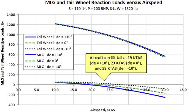
FIGURE 13-33 Main landing gear and tail wheel reaction loads. Note that the tail wheel reaction load goes to zero at 20, 24, and 29 KTAS, depending on elevator deflection (de = +10°, 0°, −10°). This means the aircraft must be accelerated to those airspeeds before it is possible to lift the tail wheel off the ground.
QED
Variables
| Symbol | Description | Units (UK and SI) |
| a | Elliptical major axis length | ft or m |
| AOA | Angle-of-attack | Degrees or radians |
| AR | Aspect ratio | |
| b | Elliptical minor axis length | ft or m |
| BHP | Brake horsepower of piston engine | HP |
| c | Length of tire footprint | ft or m |
| CD | Drag coefficient | |
| CL | 3D lift coefficient of the wing | |
| CL HT | 3D lift coefficient of the horizontal tail | |
| CL0 | 3D zero AOA lift coefficient | |
| CLα | 3D lift curve slope of the wing | Per degree or per radian |
| CLαHT | 3D lift curve slope of the horizontal tail | Per degree or per radian |
| CLδe | 3D coefficient of lift generated by elevator deflection | |
| CM | Pitching moment coefficient | |
| CMGC | Mean geometric chord length | ft or m |
| cr | Root chord length | ft or m |
| ct | Tip chord length | ft or m |
| d | Deflection of gear | ft or m |
| d | Diameter of wheel | ft or m |
| d | Difference between unloaded tire radius and loaded tire radius | ft or m |
| D | Diameter of propeller | ft or m |
| D | Diameter of tire | ft or m |
| F | Force | lbf or N |
| Fdrag | Drag landing force | lbf or N |
| FL | Left landing gear friction force | lbf or N |
| Fland | Vertical landing force | lbf or N |
| FN | Nose gear friction force | lbf or N |
| FR | Right landing gear friction force | lbf or N |
| Fside | Side landing force | lbf or N |
| h | Distance to turning center | ft or m |
| H | Radial distance from outside of wheel to outside of tire | ft or m |
| hCG | Height of center of gravity above ground | ft or m |
| iHT | Incidence of the horizontal tail | Degrees or radians |
| J | Advance ratio | |
| KE | Kinetic energy | ft·lbf |
| KS | Spring constant | lbf/ft or N/m |
| LHT | Lift of horizontal tail | lbf or N |
| lHT | x-distance from CG to AC of horizontal tail | ft or m |
| LR | Lift ratio | |
| LW | Lift force of wing | lbf or N |
| M1,M2 | Landing gear reaction moments | lbf·ft or N·m |
| MW | Moment of wing about the CG | lbf·ft or N·m |
| N | Number of main wheels featuring brakes | |
| P | Average pressure on tire | lbf/ft2 or N/m2 |
| q | Dynamic pressure | lbf/ft2 or N/m2 |
| R1,R2, R3, R4 | Landing gear reaction forces | lbf or N |
| RL | Loaded radius | ft or m |
| RM | Main gear reaction force | lbf or N |
| RN | Nose gear reaction force | lbf or N |
| RPM | Revolutions per minute of propeller | RPM |
| RT | Tail wheel reaction force | lbf or N |
| Rturn | Turning radius | ft or m |
| S | Wing planform area | ft2 or m2 |
| Se | Elliptical area (of tire) | ft2 or m2 |
| SHT | Horizontal tail planform area | ft2 or m2 |
| T | Thrust | lbf or N |
| tM | Mechanical trail | ft or m |
| V | Airspeed | ft/s or m/s |
| VC | Design cruising speed | ft/s or m/s |
| VLOF | Liftoff speed | ft/s or m/s |
| VS0 | Stalling speed in landing configuration | KTAS |
| VS1 | Stalling speed with flaps retracted | ft/s or m/s |
| W | Weight of aircraft | lbf or N |
| W | Width of tire | ft or m |
| Wheel base | x-distance between main gear and nose/tail gear | ft or m |
| Wheel track | y-distance between wheels of main gear | ft or m |
| wt | Wheel track | ft or m |
| xM | x-distance from CG to main gear | ft or m |
| xN | x-distance from CG to nose gear | ft or m |
| xT | x-distance from CG to tail wheel | ft or m |
| xW | x-distance from CG to AC of wing | ft or m |
| yT | y-distance between CG and thrust | ft or m |
| ΔwL | Change in left wheel moment arm | ft or m |
| ΔwR | Change in right wheel moment arm | ft or m |
| Δx | Displacement of rudder pedal | ft or m |
| Δy | Displacement of brake cylinder piston | ft or m |
| αstall | Stall angle-of-attack | Degrees or radians |
| αTO | Take-off angle-of-attack | Degrees or radians |
| δe | Elevator deflection angle | Degrees or radians |
| ϕ | Landing gear retraction angle | Degrees or radians |
| ϕ | Tail wheel spindle axis angle/rake angle | Degrees or radians |
| ηp | Propeller efficiency | |
| μ | Ground friction coefficient | |
| θ | Caster angle | Degrees or radians |
| θ | Overturn angle | Degrees or radians |
| θ | Tipback angle | Degrees or radians |
| θ | Turning angle of nose gear | Degrees or radians |
| ρ | Density of air | lbf/ft2 or N/m2 |
References
1. Pazmany L. Landing Gear Design for Light Aircraft. vol. 1 Ladislao Pazmany 1986.
2. Goodyear Aircraft Tire Data Book. Goodyear Tire and Rubber Company 2002.
3. Anonymous. Gates Learjet 35A/36A FAA Approved Airplane Flight Manual. Gates Learjet Corporation 1983.
4. Curry NS. Aircraft Landing Gear Design: Principles and Practices. AIAA Education Series 1988.
5. Niu Michael Chun-Yung. Airframe Structural Design. Conmilit Press 1988; p. 439–441.
6. In: http://groveaircraft.com/brakedesign.html.
7. Sengfelder G. German Aircraft Landing Gear. Schiffer 1993.
8. Stinton D. The Design of the Aeroplane. Collins 1983.
1The same actually holds when designing the cabin or cockpit. Heads or limbs penetrating a critical structure or the OML are often the result of a didn’t-think-through attitude.
2For instance see selected Goodrich products.
3Which would be calculated using ![]() where Ixx is the mass moment of inertia about the roll axis and m is the mass of the airplane.
where Ixx is the mass moment of inertia about the roll axis and m is the mass of the airplane.