
Aircraft Conceptual Layout
Abstract
The chapter presents information intended to help the designer justify the selection of a specific aircraft configuration. First, in a section aimed at the student of aircraft design, the reader is introduced to various aircraft components. This is intended to improve the basic appreciation for the complexity of aircraft structures and systems. Then, the chapter details the pros and cons of a number of configuration styles. Among those are wing position and shape, landing gear style, fuselage and cabin type, engine type and location, as well as tail configuration is discussed. The chapter is intended to help the designer develop a keener eye for the implications of selecting a particular configuration to increase awareness that can avoid costly mistakes for any company designing a new aircraft. Finally, a weighted down-selection matrix method is presented as one way to select a particular configuration. It is aimed at those designers who want to evaluate the advantages and disadvantages of the proposed configuration selection.
Keywords
Low-wing; mid-wing; high-wing; parasol-wing; dihedral; monoplane; biplane; triplane; sesquiplane; canard; tandem wing; canopy; roofed-cabin; pusher; tractor; thrust effects; taildragger; tri-cycle; retractable; floats; mono-wheel; tandem wheel; outriggers; tail configuration; down-selection matrix
Outline
4.1.1 The Content of this Chapter
4.1.2 Requirements, Mission, and Applicable Regulations
4.1.3 Past and Present Directions in Aircraft Design
4.1.4 Aircraft Component Recognition
4.2 The Fundamentals of the Configuration Layout
Impact on Flight and Operational Characteristics
4.2.4 Wing Structural Configuration
4.2.8 Landing Gear Configurations
4.1 Introduction
Of the seemingly countless tasks confronting the aircraft designer, one of the most important is the determination of a suitable configuration. Should it be a monoplane or a biplane; a single-engine or a multiengine; an unmanned aircraft or one with 800 seats? Should it be driven by a propeller or a turbofan? If propeller-powered, should it be a pusher or a tractor? What layout will truly best serve the mission of the airplane? The answers to such questions have a profound impact on all other tasks and, thus, are of substantial importance to the entire design process. Today’s aircraft designer has access to an enormous database of possible configurations. Many of those have a long operational history that allows the designer to realistically evaluate important pros and cons, and predict their capabilities more accurately than possible before. Some even argue that not many configurations remain to be invented. It is no exaggeration that when it comes to issues like the positioning of wings, landing gear, and engines; or the shape and size of stabilizing surfaces; and even aesthetics, the modern designer can practically go window-shopping for ideas using this vast database.
Aesthetics (also discussed in Section 1.1.2) is a sensitive topic for many. It turns out that the looks of an airplane play a very important role in its marketability. There really is no true method of defining good looks; beauty is in the eyes of the beholder, as mentioned before. It is tempting to propose that the number of produced and sold units of a particular aircraft versus another might serve as an indicator, but even this is unreliable because there are so many other factors that affect sales; for instance the cost of acquiring, maintaining, and operating the airplane can easily offset what most people would consider “good looks.” In spite of that, the designer must always keep in mind that the customer, who spends an exorbitant amount of money on a brand new aircraft, wants the purchase to look good. He or she wants it to look like the million dollars just spent. The designer of new aircraft should be mindful of the psychology of the process of purchasing. The cost of an expensive consumer product is sometimes justified by its looks. With respect to aircraft, the competent designer not only knows what the most efficient aerodynamic shape looks like, but also that some of that efficiency may have to be sacrificed in favor of improved looks. An ugly but efficient aircraft is less likely to sell than a good-looking airplane that is slightly less efficient. Of course, sometimes efficiency and good looks go hand-in-hand. For instance, winglets have a wide appeal and they tend to improve the efficiency of aircraft. There are plenty of examples of the opposite, i.e. a feature that improves efficiency but looks awkward, although none will be brought up here to prevent bruised feelings.
Then, there are some designers of aircraft who appear to try their best to stay away from “conventional” configurations. Some strive to put their mark on aviation through original and unorthodox geometry. While the originality of such thinking is to be respected and encouraged, the current state of aircraft design is also to be respected. Originality should be the consequence of mission requirements and not for the sake of being original. There is a good reason why most airplanes look the way they do: evolution. The airplane, as we know it today, is the consequence of an evolution that shares many parallels with biological evolution. A multitude of configurations has been “selected” by the market due to cost-effectiveness (purchase and operational price) and safety statistics, while many others have been weeded out of the pool of options. One hundred years of aircraft evolution have yielded a number of geometries that have proven to be safe and reliable. There are plenty of configurations that simply haven’t cut it. Reliability is a very important property if you have to pay for the operation of an aircraft. Safety is a very important property if you have to fly in one. And safety is more important than reliability. The designer who pursues an unconventional aircraft configuration should be concerned about operational safety and reliability. He or she must have the big picture in mind. Safety and reliability are far more important than a signature shape. The selection of the configuration will affect not only areas such as performance and handling, but also areas often less considered, such as maintenance and operation in the field. While the capability of our design methods is deep enough to allow for the design of unconventional aircraft operating in attached flow, the same does not hold for separated flow conditions. And that’s where things tend to go wrong.
A part of the conceptual layout is the determination of the class of aircraft the new design belongs to. This is important for several reasons. First, it greatly reduces the number of aircraft one needs to evaluate for comparison purposes. Second, it defines the class of aviation regulations that must be considered in the design of the aircraft. Aircraft are typically placed in order based on characteristics, such as number of engines, mission, and performance. And, third, it allows one to include and exclude specific problems the various types of aircraft have experienced. It is also of importance that the aircraft designer is able not only to identify aircraft components, but also knows their specific purpose on the aircraft. This is discussed in Section 4.1.4, Aircraft component recognition.
In this chapter, we will present various examples of aircraft, many of which are being operated on a daily basis. This will be followed by the introduction of a number of common and not so common aircraft configurations for the purpose of giving the aspiring aircraft designer some ideas as to what shape to select for a particular mission. The advantages and disadvantages of each configuration will be discussed, as this is an imperative part of the selection process. Also note that a more detailed discussion of wings, tails, and high-lift devices is also presented elsewhere in this book. The purpose of the chapter is to help the designer ponder the implications of the selected configuration on the scope of the design process.
Note that more details on the conceptual design of specific airplane types are provided in Appendix C, provided online.
4.1.1 The Content of this Chapter
Section 4.2 presents a number of important design considerations and discusses their advantages and disadvantages. This is intended to help the designer to develop a keener eye for the implications of selecting a particular configuration. This awareness can avoid costly mistakes for any company designing a new aircraft.
4.1.2 Requirements, Mission, and Applicable Regulations
As stated in Step 1 of the Conceptual Design Algorithm for a GA Aircraft presented in Section 1.3.1, the design process begins by the execution of the statement: “Understand requirements, mission definition, and the implications of the regulations to which the airplane will be certified.” This means:
(1) The plane's requirements simply mean: how far, how fast, how high, how heavy, how long a take-off and landing distance etc, must the airplane be capable of.
(2) The airplane's mission simply means what it is the airplane is supposed to do. In other words, is it a passenger transport plane that takes off, climbs to the cruise altitude, and cruises for a while before descending for landing? Or is the mission more complicated (see Figure 4-1)? Whatever the mission, its details should be clearly defined for the reasons stated in Section 1.1.2, Important elements of a new aircraft design.

(3) Regulations refers to the airplane's designer clearly knowing which regulations the airplane will be designed to.
These three have a profound impact on the airplane configuration.
4.1.3 Past and Present Directions in Aircraft Design
It may strike many as a surprise that aircraft design would be affected by fashion. It would seem that something as vain as style would be beyond engineering, but a review of the history of aviation reveals this is not the case. It is actually vibrant with shapes and components that were popular at one time, but later became a part of history, although others stuck around and became the norm. Table 4-1 lists a few fads that are clearly visible by observing the evolution of the aircraft from early times to modernity.
TABLE 4-1
| Era | Fashion |
| 1910s | Rotary engines, biplanes, engine-synchronized machine guns (necessity more than fashion). |
| 1920s | Corrugated aluminum aircraft, wheel fairings for fixed landing gear, open cockpits–closed passenger cabins. |
| 1930s | Engines inside the wing, the birth of scheduled passenger transportation, closed cockpits–closed cabins, retractable landing gear, round wingtips, taildraggers, seaplanes. |
| 1940s | Elliptical wings, engine supercharging, sliding canopies for fighters, tricycle landing gear. |
| 1950s | Passenger turboprops, Jetsons’-style jet geometry,1 supersonic aircraft. |
| 1960s | VTOL aircraft, supersonic passenger transport, Yehudi flaps for commercial jet aircraft, multi-slotted Fowler flaps for jetliners, low-bypass-ratio jet engines, delta wings for fighters. |
| 1970s | Reduced field-of-view (FOV) cockpits in fighters, “walk-about-cabin” for business jets, STOL aircraft. |
| 1980s | Composites, NLF airfoils, wide-body jets, increased FOV fighter cockpits, and T-tails, more simplified high-lift system for jetliners resulting from reduction in LE-sweep angles, which was a consequence of the development of airfoils using computers. |
| 1990s | Propfans, joined wing design, high-bypass-ratio turbofans, ETOPS-certified commercial jetliners, glass cockpits for commercial jetliners, hush-kits for older jetliners. |
| 2000s | Winglets, glass cockpits for GA aircraft, LSA aircraft. |
| 2010s | Chevrons for jet engines, raked wingtips, electrical aircraft. |
1Generally, this means fuselages with a bullet-shaped nose with a Pitot sticking out of it. The term is really the author’s preference and is admittedly used to give name to something particularly difficult to describe.
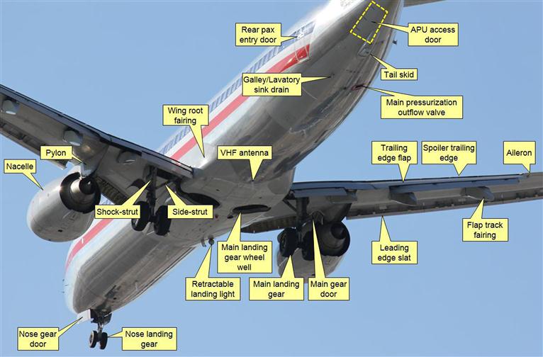
4.1.4 Aircraft Component Recognition
In the discussion that follows, it is imperative the reader recognizes the terminology used. Figures 4-2 through 4-5 are intended to familiarize the reader with the external parts of typical aircraft. All aircraft feature many parts and components that are directly exposed to airflow and affect not only the performance and operation of the aircraft, but also the cost of manufacturing and maintenance. The location of most of these components (e.g. Pitot tubes, static sources, antennas, and others) is usually the consequence of hard work which involves the various design groups coming to an agreement on the most suitable location. For instance, a static port must be installed in an area where surface pressure remains relatively constant with angle-of-attack. This area, on the other hand, may be prime real-estate for an antenna, which requires an unobstructed signal path in order to work well, or the installation of a NACA duct for an inlet of cooling air for the avionics or other components. Having an understanding of where specific components may have to be placed on the aircraft will help the designer anticipate and avoid possible detail design conflicts.
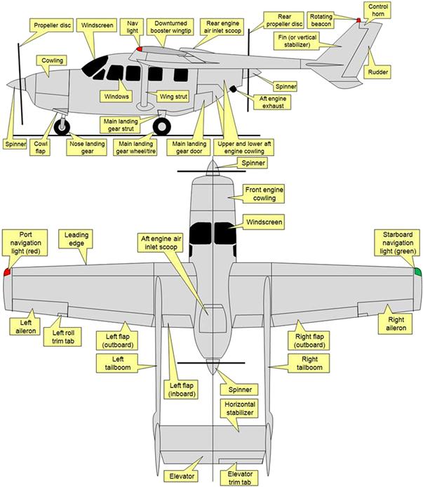


The main components of an aircraft are: wings; fuselage; nacelle; empennage; horizontal and vertical tail; power plant; and landing gear, to name a few. These components can be broken down further into subcomponents. For instance, it is possible to break the wing into a main element, flap, aileron, spoiler, wingtip, and so on. Sometimes it is convenient, if not necessary, to break these down further. For instance, the flap consists of a spar, ribs, skin, attachment brackets, access panels, and so on. Of the above primary components, three need some further definition:
A fuselage is a structural body not intended to generate lift (although it may) whose purpose is to contain engine, fuel, occupants, baggage, and mission-related equipment, although not always simultaneously. A fuselage is always mounted to lifting and stabilizing surfaces, if not directly, then through structural members.
An empennage refers to the horizontal and vertical tail of a conventional aircraft configuration. The word is of French origin, where it refers to the tail feathers of an arrow. Sometimes it is taken to mean the general region or assembly of the fuselage that contains both the horizontal and vertical tail.
A nacelle is a fuselage that does not carry an empennage. Nacelles usually carry an engine, but may or may not house occupants. Nacelles can be mounted to a lifting surface, such as a wing, or to a non-lifting geometry like a fuselage.
4.2 The Fundamentals of the Configuration Layout
This section presents important concepts to keep in mind when selecting a particular configuration, as well as arguments for and against their selection.
Before starting the design of an airplane the novice designer should familiarize him/herself with Table 4-2, which shows typical dimensions for some selected classes of aircraft. Students of aircraft design who have yet to develop a keen sense for dimensions and weights of airplanes are encouraged to study the table in detail. This is not to say that a new design cannot be outside the shown limits, but rather that most aircraft ever built fall somewhere between the extremes cited. If the specifications of the new airplane fall outside these limits, inadvertently, the table may encourage the designer to take a second look at the numbers.
TABLE 4-2
Typical Properties of Aircraft Based on Class [1]
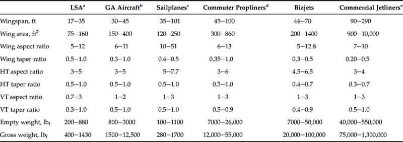
aIncludes typical homebuilt and other experimental category aircraft.
bRefers to 14 CFR Part 23 or EASA CS-23 certified aircraft.
dRefers to the typical turboprop powered domestic aircraft and a handful of piston aircraft.
eRefers to 14 CFR Part 25 passenger jetliners used both domestically and internationally.
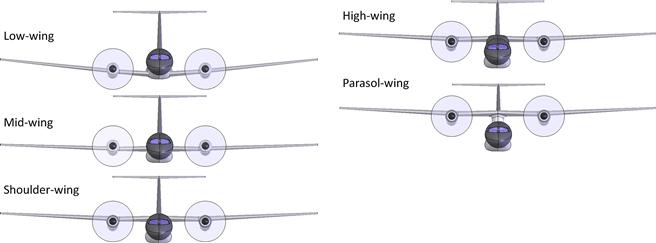
4.2.1 Vertical Wing Location
One of the most prominent features of any aircraft is the vertical placement of the wing. This section presents five common such configurations and presents arguments for and against each. The vertical wing location may end up being based on a number of factors such as:
| Accessibility (freight, passengers, fuel) Length of landing gear legs Stability and control Protection of occupants Operation (amphibians, land only) Aesthetics |
Field-of-view Manufacturing issues Structural issues Interference with passenger cabin Aerodynamic drag Manufacturer’s (or designer’s) preference |
Ideally, the designer weighs each factor and decides the best position for the wing. It is important to avoid succumbing to biases such as “low-wing airplanes are always faster” or “high-wing airplanes have better stall characteristics.” There is no law of nature that says that one or the other is superior. It all depends on other details, such as overall drag, airfoil selection, geometry of the airplane, and so on. It is the interaction of the components constituting the complete aircraft that matters. In fact, a case can be made that a high wing will be faster as it has less destructive effect on wing lift over the fuselage. There are fast and slow examples of either configuration. Examples include the low-wing P-51 Mustang (fast) versus Evans VP-1 Volksplane (slow) and the high-wing Mitsubishi MU-2 (fast) versus the Piper J-3 Cub (slow). The most common vertical wing placements are shown in Figure 4-6. The designer is urged to consider the consequences of the selection that are detailed below.
Field-of-view
The high-wing configuration offers a great field-of-view downward, whereas it may obstruct the pilot’s view when banking (turning). This is an important issue for small airplanes (when the pilot sits below the wing) as it arguably increases the risk of mid-air collision for such aircraft. Therefore, the designer should consider the installation of transparencies on the roof to remedy this shortcoming.
The opposite holds true for a low-wing configuration. There is less downward visibility, but superior field-of-view in the direction of the turn. Of course, this argument does not hold for large commuter aircraft because the cockpit is placed far ahead of the wing. On small airplanes, the shoulder wing configuration improves visibility upward and downward, but requires the wing to be swept forward in order to ensure the center of gravity (CG) is placed properly on the mean geometric chord (MGC).
Impact on Airframe Design
The high-wing configuration, for a light aircraft, might rely on a gravity-fed fuel system, whereas a low-wing configuration may require a fuel pump (an added system). Fueling a high-wing aircraft is a drawback, because the fuel tanks are generally in the wing with the fuel caps on top of the wing. This requires a step ladder, which may not be available at all airfields. Larger airplanes solve this issue by featuring fueling points in the fuselage, where fuel is pumped under pressure. That option is impractical for GA aircraft that operate off airfields that do not have such equipment.
Entry into a high-wing configuration is often as simple as opening a door and stepping into the cabin. Small aircraft with low wings require a reinforced walkway on the wing and an external step that usually remains exposed to the airstream.2 This usually means a walkway with sandpaper texture that is known to detrimentally affect flight characteristics of some aircraft.3
Many high-wing airplanes use wing-struts, which substantially reduce the shear and bending moments (see Section 4.2.4, Wing structural configuration), rendering the wing structure lighter than if built using cantilevered beam principles. Such struts are subjected to tension forces in normal flight, whereas struts on low-wing aircraft would be in compression, exposing them to a buckling failure.
The structure of the low wing can be used to attach landing gear, resulting in shorter and lighter landing gear. In small aircraft, the low configuration also allows the occupant seats to be attached to the main spar and the fuselage structure necessitated by the aft spar (or shear web). Both result in a more efficient structure.
The low, high, and parasol wing configurations open up the passenger volume as the wing structure does not pass through the cabin. This is very important in the design of passenger aircraft. In contrast, the shoulder and mid-wing configurations both require the wing spar to be accommodated inside the cabin. Frequently, in single- and two-seat variants of aerobatic aircraft, this is solved by placing the main spar well ahead of the occupant, typically in the area of the instrument panel. This allows the legs of the pilot to pass comfortably below the structure.
The mid-wing configuration was widely used in aircraft design during the Second World War. Bombers from the era featured wings with hard points for bombs in the wing center structure and yet providing underbelly volume. The configuration is never used in large passenger aircraft as the wing structure would penetrate and occupy a part of the cabin, in addition to making traffic between forward and aft cabin impractical. In spite of this, the configuration has been used in a few aircraft; for instance, the 10-passenger IAI-1124 Westwind business jet and the 6-seat Piper Aerostar (formerly Ted Smith Aerostar). A possible remedy to the structural detriment could be special hoop frames that would allow the wing loads to be reacted “around” the enclosed volume. However, such a structure would be very inefficient and, thus, heavier. The Hamburger Flugzeugbau HFB-320 Hansa Jet, manufactured in the late 1960s and early 1970s, solved the problem with a forward-swept mid-wing whose primary structural element was behind the cabin. That configuration is not practical for the typical commuter aircraft. Although not a GA aircraft, the General Dynamics F-16 is an example of a mid-wing aircraft that solves the problem with stout machined hoop-frames around its single engine. These are justified by the engine placement.
Impact on Flight and Operational Characteristics
High-wing aircraft are less affected by ground effect and, thus, float less than low-wing aircraft when landing. This may be an important consideration in the design of bush-planes, where accuracy in making a landing spot on a short unprepared runway is imperative. Additionally, a low position of the wing may increase the risk of an accidental ground strike when operating off unprepared fields. More bush planes are of the high-wing configuration than the low-wing.
The configuration increases roll stability (or dihedral effect – Clβ), although this may present a disadvantage for heavy transport (e.g. cargo) aircraft, requiring anhedral to remedy. In small aircraft, the mid-wing configuration is frequently chosen for aerobatic airplanes to ensure neutral roll stability. This allows rapid roll maneuvers with minimum yaw coupling, something very desirable for precision aerobatic maneuvers. A low wing position has limited lateral stability, requiring the wing to feature dihedral angle to make up for it.
The high and low wing configurations often present some challenges in the geometry of the wing/fuselage fairing. Mid wings usually need smaller wing root fairings, although this may not hold for the aft part of the wing. It is a good configuration for aerobatic aircraft and a number of such designs are popular. Among those are the Slick series of aerobatic aircraft (Slick Evolution, Slick 360, etc.), Laser Z-300, Sukhoi Su-31, and Extra 300.
Snow bank collision is an interesting and surprising consideration to keep in mind for the design of aircraft primarily slated for operation off unimproved strips in cold climates (e.g. Alaska). Many isolated cold-climate communities rely on aviation to transport supplies in winter. Unimproved strips are then prepared by pushing snow on frozen lakes to form a runway, leaving snow banks several feet high along the perimeter of a very narrow runway. These can pose challenges to pilots of low-wing aircraft attempting to land in crosswinds.
Parasol Wings
Parasol wings are not common in modern aircraft design, although a few examples exist. The configuration consists of the wing separate from and placed high above the fuselage. From a certain point of view, the fuselage is hung from below the wing. The best-known aircraft to feature such a wing is undoubtedly the Consolidated PBY-5 Catalina (Figure 4-7) which was designed in the 1930s. Among others that sport the configuration are a series of aircraft built by Dornier, such as the Do J Wal (designed in the 1920s), Dornier Libelle (1920s), Do-18 (1930s), Do-24 (1930s), Dornier Seastar (1980s), and the Dornier S-Ray 007 (2000s), an amphibious sport aircraft. The configuration is beneficial for propeller-powered amphibious aircraft if the engine is mounted on the wing, helping to keep the propeller out of the spray of water.
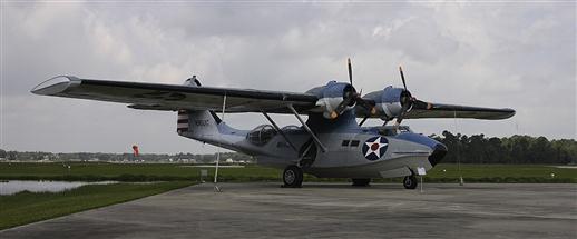
FIGURE 4-7 The Consolidated PBY-5 Catalina is an example of an airplane featuring a parasol wing. (Photo by Phil Rademacher)
This placement arguably results in an aerodynamically “cleaner” and thus a more efficient wing. The absence of a fuselage restores the lift potential of the wing, yielding a lower lift-induced drag. However, it also results in two sources of interference drag, one at the fuselage side and the other at the wing side.
For wing-mounted engines, the configuration may have a lower flutter speed due to the engine mass being mounted on a relatively flexible wing structure. This is compounded by how the fuselage is separated from the wing. An additional drawback is the high thrust line of the configuration, which makes power effects noticeable to the pilot.
Dihedral effect may be excessive and may require added vertical tail area to increase directional stability to counteract its effect on dynamic stability modes such as Dutch roll.
4.2.2 Wing Configuration
Airplanes are also categorized based on the number of wings they have. The monoplane is by far the most common configuration as it is without a doubt the easiest to make aerodynamically efficient. The primary advantage of the biplane or triplane configuration is the large wing area that can be packed in a small wingspan. This allows for very maneuverable airplanes with relatively low stalling speed without flaps. The drawback of the configuration is the aerodynamic inefficiency that stems from placing the low-pressure region of the lower wing close to the high pressure region of the upper wing. This reduces the production of lift, requiring higher AOA to generate the same lift coefficient and, consequently, higher lift-induced drag.
The difference between a sesquiplane and a biplane is the shorter span of the lower wing (Figure 4-8). This improves the efficiency of the outboard part of the upper wing by enabling higher pressure to be generated on its lower surface. It also results in a phenomenon that makes the configuration ideal for agricultural aircraft: the generation of four distinct wingtip vortices that help spread fertilizer or insecticide more effectively. This book primarily focuses on monoplanes, but details of biplane design are provided in Appendix C1.1.3, Conceptual Design of Small Biplanes.
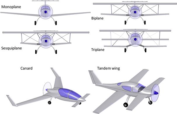
The difference between a canard and a tandem plane is in the size of the forward wing. Generally, the elevator is installed in the forward lifting surface. Both lifting surfaces generate upward-pointing lift vectors in level flight and both forward surfaces are highly destabilizing, longitudinally.
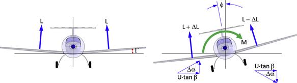
4.2.3 Wing Dihedral
The dihedral angle is the angle the wing plane makes with the horizontal. It allows the aircraft designer to provide the airplane with roll stability and a way to affect the severity of dynamic modes such as Dutch roll. Its primary effect is on the stability derivative Clβ (dihedral effect). In addition to the dihedral angle, the magnitude of the dihedral effect depends on the vertical location of the wing and sweep angle. Ultimately, the designer must predict the dynamic stability characteristics of the airplane design and evaluate the appropriate dihedral angle.
Figure 4-9 shows an airplane at airspeed U, banking through an angle ϕ. The banking results in a side-slip, which effectively results in a yaw angle β. The yaw angle results in side flow component amounting to U·tan β, which when combined with the change in vertical flow due to the roll causes a net change in angle-of-attack, Δα, on each wing. The subsequent change in lift (ΔL) on each wing is shown in the figure, and it generates a restoring rolling moment (one that tends to rotate the aircraft back to level flight), here denoted by the letter M.
Common dihedral configurations are shown in Figure 4-10. Of these the three on the left are most commonly used. The cranked dihedral is used extensively on the French Jodel and selected Robin aircraft, as well as on some sailplanes. However, it is also featured on the Argentinian FMA IA-58 Pucará twin turboprop ground attack aircraft and of course the McDonnell-Douglas F-4 Phantom.
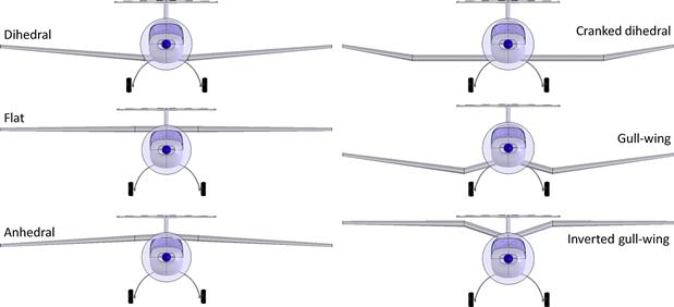
The gull-wing configuration is fairly rare, being most famously used on the Vought F4U Corsair, where its purpose was to increase the propeller clearance for carrier operations. It was also used for various reasons on the Blohm & Voss BV-137, Caproni Ca-331b Raffica, Dewoitine HD-780, Fairey AS-1 Gannet, Heinkel He-112 B, and Junkers Ju-87 Stuka.
The inverted gull-wing configuration is often used for twin engine seaplanes, where it helps take wing-mounted engines and propellers away from the spray of water. It is featured on the Beriev Be-6, Be-12, Chyetverikov MDR-6, and Moskalev 16 amphibians and seaplanes. It is also used on the Göppingen Gö-3 Minimoa sailplane, and the PZL P-1, PZL P-11, Piaggio P-166, and Supermarine 224 landplanes. The Stinson SR-10 is an example of an aircraft that could fit into this class, featuring a wing whose upper surface has a distinct gull-wing break. However, the lower surface forms a straight line and the spar does not have a break, rendering it more of a transitional form.
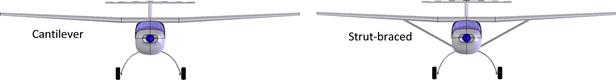
4.2.4 Wing Structural Configuration
Nowadays, the wing’s structural layout is based on either a cantilevered or a strut-braced methodology (see Figure 4-11). Both have their pros and cons, with strut-braced having a higher drag than the cantilevered configuration. However, the maximum shear and bending loads of the strut-braced wing are much less than those of the cantilevered wing, resulting in a lighter wing structure.
As an example, consider Figure 4-12, which shows a strut-braced (top) and cantilevered wing (bottom) subject to an equal aerodynamic load, represented by the simplified trapezoidal lift distribution. The lift distribution of real wings is not trapezoidal, but the accuracy of its shape is not important to the point being made here.

FIGURE 4-12 Shear and moment diagrams expose the structural implications of selecting a strut-braced versus cantilevered wing configuration.
The upper part of the figure shows where the maximum shear and bending moment occurs on the strut-braced configuration. Their corresponding magnitudes are given by Vmax and Mmax, respectively.
The lower image shows shear and moment diagrams for the cantilever configuration. It shows the maximum shear is 2.3× greater than that of the strut-braced wing and the moment is 4× greater. Conversely, although not shown, there is a substantial compression load that must be reacted between the wing-to-fuselage and strut-to-fuselage attachment points. It follows that the structural weight of the strut-braced wing will be much less and it should be given a serious consideration if aerodynamic efficiency is not a factor.
4.2.5 Cabin Configurations
Here, the discussion of cabin configuration will be limited to light aircraft only, as cabins for passenger aircraft are presented in more detail in Chapter 12, The anatomy of the fuselage. Typically there are two kinds of cabin styles: canopy and roofed (see Figure 4-13). An advantage of the roofed cabin is increased protection in the case of a turnover accident. This configuration requires an entry door to be added, preferably one on each side. These may present some fit and function issues in production, although similar arguments can be made against the canopy. The roof also limits the field-of-view.

A canopy offers exceptional field-of-view to the pilot, which is very desirable for many travelers, in addition to reducing the risk of a mid-air collision. However, turnover mishaps are of considerable concern for such aircraft. This is reflected in the regulation 14 CFR 23.561, General. The applicant must demonstrate compliance by reinforcing the window frame to which the windscreen is attached to prevent a collapse that would harm the occupants. Often called the A-pillar, this frame effectively becomes a rollover cage, increasing its girth and weight.
Excessively high cabin temperatures due to greenhouse effects are a drawback of the canopy. The configuration should allow for a canopy that can be left open during ground operations (while taxiing) for cabin cooling. This is particularly important if the airplane does not have air conditioning (such systems are not common in small aircraft). Reduction in green-house effect makes the roofed cabin configuration a viable candidate.
The acrylic canopy must be installed and operated with care (if flexible), as cracks may develop around fastener holes. The configurations with the canopy should feature an appropriate mechanism to prevent it from opening in flight due to aerodynamic forces. For instance, should the latching mechanism fail in flight, an aft-hinged or side-hinged canopy is at risk of opening due to aerodynamic forces. If the canopy departed the aircraft, it might damage the HT or VT, possibly rendering the vehicle uncontrollable. If the canopy opened up and stayed with the vehicle, a substantial asymmetry in loads could result rendering the aircraft uncontrollable as well. Of course, either canopy-mounting technique makes it easier to board the airplane than a forward-hinged canopy.
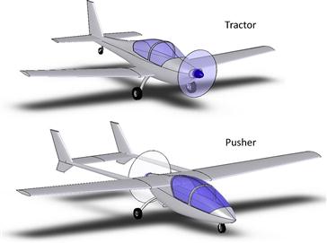
4.2.6 Propeller Configuration
There are two fundamental ways to mount a propeller to an engine; as a tractor or as a pusher (see Figure 4-14). Either configuration is practical for piston engine, gas turbines, and electric motors.
The pros and cons of these configurations are discussed in detail in Section 14.1.2, Propeller arrangement.
The tractor configuration is a proven arrangement that is generally suitable for most applications. It provides undisturbed air for the propeller although the higher airspeed and lower quality air increase the drag of the body immersed in the propwash.
The pusher propeller is a good solution to some specialized mission requirements, for instance for single-engine reconnaissance or observation missions. This will remove the propeller from the field of view and allow a high-visibility cockpit to be designed. There are a number of issues the designer should be aware of. Propeller manufacturers are generally apprehensive about the arrangement as it introduces problems not always anticipated by the designer. Some of those are detailed in Section 14.1.2, Propeller configurations. However, the aspiring designer should not let this aversion influence the introduction of a particular configuration, as propeller manufacturers are happy to work on any such project. They only want the designer to recognize the shortcomings.
4.2.7 Engine Placement
As intuition would hold, the placement of any significant source of force on an aircraft is of great concern. Engine thrust is an example of such a source and, in magnitude, is second only to that of the wing lift. The moment generated by this force must be arrested by the stabilizing surfaces. If the engine thrust is placed above the CG of the airplane, the consequence will be a nose pitch-down moment that, on conventional aircraft, must be trimmed out using elevator trailing edge up (TEU) deflection (see Figure 4-15). The opposite holds for an engine whose thrustline is below the CG. The higher the thrust, the greater is the deflection required, although a better method is to enlarge the size of the elevator or increase the planform area of the horizontal tail, or a combination thereof.
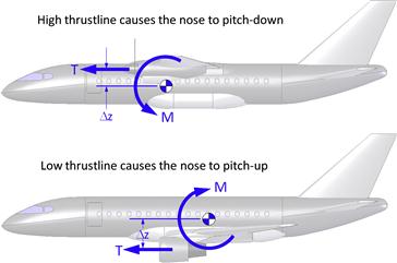
In short, the larger the value of Δz is in Figure 4-15, the larger must be the elevator authority. The moment generated by the thrust must be taken into account during the design phase to prevent the dangerous potential of an undersized stabilizing surface. The possibility is serious enough to warrant a discussion in Section 23.3, GA aircraft design checklist.
Noticeable power effects are another consequence of engine placement. These can be quite complicated for propeller-powered aircraft, as is discussed in detail in Section 14.2, Propeller effects, and some of those are shared by the jet engine. While not necessarily dangerous, they can be particularly annoying to the pilot. If each power change calls for swift pilot reaction, the airplane will simply be less pleasant to fly. In spite of such nuisances, some aircraft require the thrustline to be high, such as seaplanes, as this protects the propeller from water spray. For such airplanes, pitch changes with power settings are accepted because it saves the propeller. For the operators, it is just something the pilot has to get used to.
Another important consideration for the layout of a propeller is the effect of propwash. If it flows over a control surface like the horizontal and vertical tail, it will improve the control authority at high power settings, but the higher airspeed also increases the drag of the surface, albeit modestly.
Figure 4-16 shows a number of common engine placements. Configuration A features the jet engines in pods (or nacelles) mounted to the aft part of the fuselage. This configuration was first introduced in the 1960s in the French Sud-Est Caravelle passenger jetliner. The placement results in modest, if any, pitch effects and is intended to reduce engine noise in the cabin, although noise in the aft-most part of the cabin is increased, if anything.
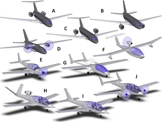
Configuration B mounts the engines below the wing, using pylons. This configuration will result in substantial pitch effects, although some kind of stability augmentation system (SAS) can be employed to reduce the effect. The configuration is vulnerable to foreign object damage (FOD) but, in spite of that, is the most common engine placement found on passenger jetliners. The placement is beneficial from a structural standpoint as the weight of the engines introduces bending moment relief, which ultimately reduces airframe weight. Additionally, its forward position has a favorable effect on the flutter characteristics of the wings.
Configuration C features the engine above the wing and will generate nose pitch-down moment at high thrust settings. The configuration was first introduced in the 1970s on the German WFV-Fokker 614 jet, but later adopted on the Hondajet, where the intent is to avoid the ground clearance problem of under-wing nacelles. However, it can introduce peculiar aerodynamic and flutter issues [2,3].
Configuration D is a twin-engine turboprop aircraft with propellers mounted in nacelles on the wing. This is the most common method to install turboprops in such aircraft. However, it can lead to serious asymmetric thrust condition in a one engine inoperative (OEI) situation. Also, the rotating propellers can cause a so-called whirl-flutter or subject the airframe to fatigue through life-cycle oscillations (LCO) of the engine-wing combination.
Configuration E is a tractor propeller configuration, which has limited thrust effects due to engine placement, but more due to the physics of propeller thrust generation.
Configuration F is a seaplane, with the engine placed on top to protect the propeller from sea spray. It is a pusher configuration. It suffers from substantial pitch effects but, as stated earlier, this detriment is accepted due to the protection the prop enjoys.
Configuration G is a pusher configuration, which has the thrustline sitting somewhat high, although this is not as much of a problem as one might first think. The propeller will help keep flow attached on the aft part of the fuselage. It is subjected to some drawbacks of the pusher propeller configuration, although the particular configuration shown improves safety by making it hard to accidentally walk into a rotating propeller.
Configuration H is a single-engine jet that features a turbofan engine on a pylon on top of the fuselage. It would suffer from substantial pitch effects, although this can be partly remedied by deflecting the nozzle a few degrees up. The advantage of the engine placement is that it places the inlet in the airstream so it has a high pressure recovery, even at high angles-of-attack (AOA).
Configuration I features a buried engine, which results in minimal pitch effects with thrust, if any. The drawback is that the bifurcated inlet reduces pressure recovery at the front face of the compressor, reducing maximum available thrust. The bifurcated duct is also problematic if the airplane is operated in icy conditions as ice will accrete in the bend of the inlet.
Configuration J is a small four-seat twin-engine propeller-powered aircraft, suitable as a light VIP transport or reconnaissance aircraft. Its piston engines are mounted on the wings and must sit high enough to prevent damage to the propellers due to small objects that might be thrown from the operation of the nose landing gear on unimproved runways, or if it is subject to a flat tire on any of the landing gear. The nacelles are designed to accommodate the retractable landing gear. It features an H-tail to help generate restoring yawing moment in the case of an OEI situation.
4.2.8 Landing Gear Configurations
A large number of different landing gear configurations have been developed for use in aircraft. Six examples are shown in Figure 4-17. It should be stressed it does not show all the options, only those that are used on 99.99% of all GA aircraft. The most widely used configuration is the tricycle, followed by the taildragger. One of the advantages of a taildragger is less drag than the tricycle. An example of improvements attained by a small aircraft is that of the Cessna 150. It is claimed that converting a tricycle version of the aircraft to a taildragger gave it an increased cruising speed of nearly 8 knots. [4]. The benefit is always a function of the airplane and its overall drag, but a 4–10 knot increase in cruising speed is reasonable.
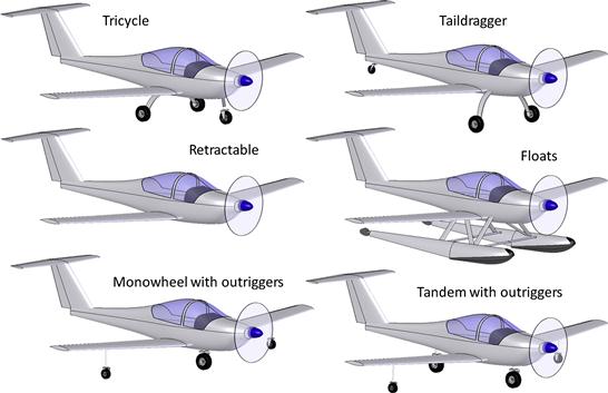
The monowheel with outriggers is a popular design for sailplanes and motor gliders like the British-designed Europa XS and the German Scheibe Tandem-Falke. The monowheel configuration reduces the drag of the landing gear. The same is true of the tandem wheel configuration, although it is rarely used in GA aircraft. The British Hawker Harrier is the best-known example of tandem wheel configurations.
Tricycle, taildraggers, mono- and tandem wheel configurations may all be retractable. Fixed landing gear will increase the drag of the airplane and, if this is the case, the designer should strongly consider wheel fairings for drag reduction. The floats increase drag substantially, but allow operation on land and water. They are still popular among many pilots who are more interested in access to obscure wilderness retreats than high airspeeds. Floats and amphibious airplanes are dealt with in Appendix C3, Design of seaplanes.
The tricycle landing gear makes the vehicle dynamically stable on the ground and reduces the risk of a ground loop. For this reason, it is better for inexperienced pilots and, thus, better suited for trainer aircraft. Similarly, the taildragger configuration is dynamically unstable and more prone to ground looping. It is better for operation off unimproved runways. The pros and cons of and the conceptual design of the landing gear are presented in far more detail in Chapter 13, The anatomy of the landing gear.
Taildragger aircraft have a number of advantages that make them more attractive for “bush-plane” operations. The primary advantage is the high AOA that can be generated at a low airspeed (in fact at zero airspeed). This way the airplane can be allowed to accelerate and then the pilot can quickly “drop” the tail, allowing the airplane to lift off in ground effect. Such techniques give the configuration markedly shorter runway requirements and, thus, make it better suited as a bush-plane. Interestingly, this is not always reflected in the data. For instance, the Cessna Model 180 (taildragger) and 182 (tricycle) are effectively identical excluding the landing gear. Jane’s All the World’s Aircraft 1970–71 [5] reports each having identical T-O and landing distances at the same weight, but the 180 is favored as the bush-plane option, providing evidence that pilot technique is imperative. The configuration is better suited for operation off unimproved landing strips because two wheels on the ground reduce the possibility of the landing gear hitting ground obstructions (large rocks or other obstructions) during the T-O run (two wheels versus three).
The taildragger configuration is generally thought to be harder to land and maneuver on the ground than a tricycle gear due to a high deck angle, which makes it harder to see over the nose of the airplane. This configuration is usually used on small aircraft, although it has been featured on large aircraft. The largest taildragger ever built is the eight-engine Soviet Tupolev ANT-20 Maxim Gorky, with a gross weight of 116,600 lbf. The Curtiss C-46 Commando is another large taildragger, although its gross weight of 48,000 lbf is dwarfed by the ANT-20.
The total structural weight of the float is the highest, but least for the monowheel. The structure required to react the main landing gear impact load will weigh less than the structure required to react the impact loads of both tricycle and taildragger. The configuration is also the least expensive to manufacture. It is a drawback that it is vulnerable to crosswinds and too much taxiing on the ground. The same holds for the tandem wheel.
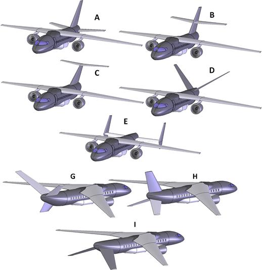
4.2.9 Tail Configurations
A number of possible tail configurations are shown in Figure 4-18. Configuration A is a conventional tail, B is a cruciform tail, C is a T-tail, D is a V-tail, E is an H-tail, G a Y-tail, H an inverted Y-tail, and Configuration I is an inverted V-tail. The pros and cons of these tails are detailed in Chapter 11, The anatomy of the tail, and will not be further addressed here.
4.2.10 Configuration Selection Matrix
Many manufacturers of aircraft know up front what configuration is to be designed. Regardless of the internal debate that may take place, and to which we are not privy, the history of aviation shows there are certain themes that present themselves in these designs. All single-engine Cessna aircraft are high-wing (except the Ag Wagon and Ag Cat agricultural aircraft). All Piper and Beech are low-wing (except the Piper Cub and Tri-pacer), as are all Mooneys, which also feature their signature straight LE horizontal and vertical tails. However, this is not always the case and the resulting configuration is a consequence of internal debate. In this section, a method to help with the configuration selection is presented (see Table 4-3). Often, the selection is compounded by the fact that all candidate designs can be shown to meet the performance and operational requirements. An observation of modern-day regional jets reveals that a number of dissimilar configurations can clearly perform the design missions effectively. Aircraft as disparate as the Dornier 328 (high wing, engines on wing), Bombardier CRJ200 (low wing, aft podded engines), and Embraer 175 (low wing, engines on wing) are examples of this. Granted there is a difference in fuel efficiency and the economics of each, however, what are the reasons behind these configurations? Why would these three manufacturers come to such different conclusions about their particular configuration?
TABLE 4-3
Example of the Down-selection of a Two-seat, Single-engine GA Aircraft Configuration by Configuration Selection Matrix

If many different candidate configurations are being considered, it is prudent to evaluate each based on a list of desirable and undesirable characteristics. The selection of a configuration is something that, in particular, baffles the student of aircraft design and the less experienced (some would say less-opinionated) designer. The weighted tabulation of Table 4-3, which considers the development of a two-seat trainer aircraft, can be very helpful when down-selecting a configuration. The trick is to phrase features such that a beneficial one receives the high score and an unfavorable one a low score and to allow the same score to be given more than once.
The number and selection of “questions” should be the result of an internal evaluation, where everyone who has a stake in the outcome has an opportunity to incorporate their concerns and goals. Note that in this case, configuration B beats the other configurations although all score well, indicating they are all plausible candidates for the particular mission. The greatest drawback of this approach is that, in addition to the nature of questions included, it is very susceptible to the weighting factors, and an honest debate about each should take place prior to the evaluation. The reader should keep in mind it is presented here as one, and not the only approach.
Variables
| Symbol | Description | Units (UK and SI) |
| α | Angle of attack | Deg or rad |
| β | Yaw angle | Deg or rad |
| Clβ | Dihedral effect | |
| ϕ | Bank angle | Deg or rad |
| Γ | Dihedral angle | Deg or rad |
| L | Lift | lbf or N |
| M | Moment (context-dependent) | ft·lbf or N·m |
| Mmax | Maximum bending moment | ft·lbf or N·m |
| T | Thrust | lbf or N |
| U | Velocity along the body x-axis | ft/s or m/s |
| Vmax | Maximum shear force | lbf or N |
References
1. Taylor, John WR. Jane’s All the World’s Aircraft. Jane’s Yearbooks, various years.
2. Fujino M, Kawamura Y. Wave-drag characteristics of an over-the-wing nacelle business-jet configuration. Journal of Aircraft. Nov–Dec 2003;40.
3. Fujino M, Oyama H, Omotani H. Flutter Characteristics of an Over-the-Wing Engine Mount Business-Jet Configuration. AIAA-2003-1942 2003.
4. Clarke B. The Cessna 150 & 152. TAB Books 2nd ed. 1993; p. 180–181.
5. Taylor JWR, ed. Jane’s All the World’s Aircraft 1970-71. Jane’s Yearbooks 1971.