An Illustration of HAZOP Study for a Continuous Operation
Abstract
A detailed description of all the stages of a HAZOP study of a continuous process, illustrated by consideration of an off-shore wellhead gas platform linked to a central process facility. The process is described and general process data provided. The issues and methodology are set out. The P&ID used is included along with cause and effect tables. A detailed report from the HAZOP study is given for two nodes.
Keywords
Continuous process HAZOP; process description; process data; P&ID; HAZOP report.
The model used for this illustration of the HAZOP study is of an offshore wellhead gas platform linked to a central process facility (CPF) by a 15 km subsea pipeline. There is no chemistry but it is essential the team understands both the physics and physical chemistry of the process.
Gas is trapped in a loose sandstone formation 2000 m below the sea bed. It is in hydrostatic equilibrium, trapped by an impervious rock over and around the sandstone rock but in water contact at the bottom. The gas exists as a dense phase, mostly methane, saturated with water vapor at 80°C and 200 bar (20 MPa). The gas flows to the surface in a production tubing of 15 cm diameter, made up from a number of threaded sections, and the pressure falls due to both frictional losses and the reduced gas static head; the flowing pressure at the top of the well is about 125 bar. The production tubing is surrounded by a number of threading casings of increasing diameter which are used in the drilling program, the number and size of casings is a function of the local geology. The effective pressure containing capacity of each casing is a function of the strength of the rocks and the cement bond between the rock and tubing. If there is a leak of gas into the annulus between each casing, there is the potential for collapse of the inner casing due to pressure reversal, so it is essential to ensure a pressure gradient “in to out” and, if leakage occurs through the threaded sections of casing, it must be depressurized. Likewise, in the upper sections of the casing, multiple path leakage could lead to a fracture of the cement. There is one major barrier (flap-type valve) set in the production tubing 250 m below the sea bed. This is called the sub-surface safety valve (SSSV—sometimes called a down hole safety valve (DHSV)) and is held open by a hydraulic signal. Loss of the signal causes valve closure, and the valve is difficult to open under high pressure differential.
The casings are terminated on a “wellhead” (Figure A3.1, pages 108–109) which is bolted to the “Christmas tree.” Within the tree is a master valve (MV) and, at an angle to the flow, a wing valve (WV); both are held open by a hydraulic signal. The emergency roles of each valve vary—the SSSV is protection against a main process event or failure of the tree, the WV is the main process valve, and the MV is used during downwell operations. Depending upon the level of emergency, the WV closes first, then the MV, and finally the SSSV. There are five wells in total in the field feeding the CPF. The flow of gas is controlled by a metal-to-metal seated manually operated valve called a choke. This is usually left in a fixed position and only adjusted occasionally. As the pressure drops across the choke, the temperature falls and two phases (condensate and gas) are produced. If the pressure drop is from 200 bar to less than about 50 bar, the temperature can fall below 0°C and ice and/or hydrocarbon hydrate solid can be formed which is controlled by injection of methanol. There is every potential for temperatures as low as −50°C during the initial start-up of the process when the gas column in the production tubing loses its heat to the rocks surrounding the well and the initial temperature of the flowing gas could be as low as 15/20°C.


The two phases flow into a collection manifold through a safety shut-off valve (ESDV2) into the subsea pipeline, about 30 m below sea level, linking the wellhead platform to the CPF, 25 m above sea level. The pipeline is rated for the maximum closed wellhead pressure (about 180 bar). There is some phase separation at low flow rates but for the most part transport is in mist or annular flow. The gas flows onto the CPF, 55 m above the sea bed, through a second safety shut-off valve (ESDV3) at the edge of the platform and then a process shutdown valve before entering a two-phase separator (Figure A3.2, pages 110–111) with a design pressure of 120 bar. Gas and liquid phases are metered separately, and the two phases then pass through a third safety shut-off valve (ESDV6) into a main subsea pipeline connecting the CPF to a shore terminal where it is processed. The data from the two flows, gas and liquid is used for reservoir performance monitoring and also apportioning products at the onshore terminal to each supplier. The main subsea pipeline has a pressure rating equal to the separator. A pig launcher can be fitted for pipeline monitoring (Figure A3.3, pages 112–113).


As the reservoir ages, the reservoir pressure falls, the flow rates decrease, and the water tends to increase. Ultimately, the reservoir tends to produce sand due to high-level pressure differentials and this is very abrasive.
Water associated with the gas is very saline and can be corrosive, so corrosion inhibitors are injected with the methanol used for hydrate suppression. The infield pipeline (and main pipeline) is protected from corrosion from seawater by sacrificial anodes, likewise the wellhead and CPF structures. There is therefore a potential electrochemical linkage between the three central elements. The pipe work is protected from corrosion internally by the corrosion inhibitor in the methanol injected for hydrate suppression.
The gas produces 1 m3 of liquids per 20,000 standard m3 gas during the separation process. The separator is designed for some “slugging” capacity and has some offline washing facility to remove sand. The liquid phase is level controlled and the gas phase is pressure controlled into the pipeline. The separator is fitted with high level alarms and shutdowns which close a shutdown valve inlet to the separation. The separator is protected against overpressure by a full-flow relief valve, discharging to a vent, sized for the maximum steady-state well flows. There are also two levels of pressure protection which first close the process shutdown valve and finally the WV.
There are other technical issues which are not discussed in this illustration as they do not serve to illustrate the study technique. These will need to be addressed in a real study.
A3.1 Methanol Injection
Methanol is used as a hydrate suppressant and is pumped by a positive displacement pump to injection pressure at the shore terminal. Corrosion inhibitor is mixed with methanol at the terminal and there is an emergency shut-off valve in the feed line at the wellhead platform (ESDV1). The main pump is fitted with a recycle pressure relief valve set at 240 bar. Each well is dosed continuously for 1 week with corrosion inhibitor. The changeover is carried out manually during the weekly inspection giving a 5-week cycle. The flow is controlled onshore to prevent hydrate formation in the pipeline.
A3.2 General Process Data
In this model, the gas flow is taken as 105 sm3/h and the pipeline is 12 in. (30 cm) diameter. The closed-in system pressure is 180 bar for which all piping on the wellhead platform and the subsea piping is designed. The CPF is designed for a pressure of 120 bar downstream of the process shutdown valve (ESDV3).
All process piping is designed for −30°C at the appropriate pressure, and the separator is designed for −40°C as it will contain liquid hydrocarbon. During process blowdown, the gas temperatures can fall to −40°C (or lower). Slugs and liquid equivalent to three riser lengths can be produced on increasing flow.
There is a fire and gas detection system which isolates the valves into and out of the CPF and depressure the process—level two. Such an event on this wellhead platform involves closure of the export valve and the WV plus MV but no depressuring. Loss of pressure in the manifold on the wellhead platform results in closure of the SSSV.
A3.3 The Issues
The inflow of gas is generally limited by the productivity index (PI) of the well. It self-limits at high demands and probably produces sand. Once the well is flowing, it must be managed to avoid sand (and water) production by fixing the choke position. Sand production can be detected by sand probes, and excessive sand production leads to erosion of the choke and piping and eventually settles out in the main pipeline. Corrosion is detected by a probe. More corrosion inhibitor is injected.
The SSSV is self-closing and cannot be opened with a pressure differential of more than a few hundred psi. SSSVs are available with compensating features and there are thousands of wells in UKCS. The MV and WV can be opened with a pressure differential and the choke operates with a pressure differential. The choke is not a shut-off valve and tends to wear and leak with time due to sand erosion.
Hydrates—a loose formation of hydrocarbon and liquid water—form above about 600 psi (4 MPa) and temperatures of about 15°C; this is controlled by methanol. Expansion of gas can produce both a water and hydrocarbon liquid phase. Temperatures as low as −50°C are possible with throttling but are composition and pressure/temperature dependent.
When the infield pipeline is isolated, it slowly pressures due to choke valve leakage and could reach the shut-in well pressure. It is possible to open the shutdown valves with this pressure differential but valve seat damage may result.
The steady-state issues are generally sand and erosion; the dynamic, start-up, and shutdown issues are hydrants and low-temperature formation. The transient states involve the potential to move from wavy flow to mist flow with slug potential, which may be exacerbated by sea bed contours. The operating pressures are high and close to the piping design pressure limits.
There are effectively six blocks for this HAZOP study:
| not included | |
| Figure A3.1 | |
| Figures A3.1 and A3.2 | |
| Figures A3.2 and A3.3 | |
| Figure A3.3 (interface) | |
| not included |

Block six—the onshore terminal has a slug catcher and gas processing equipment as well as the methanol pumps. These are out of the direct scope of this study, but it is very likely that this study will contain some actions for the hand over of information to the onshore HAZOP team.
A3.4 Methodology
There are four distinct operations:
There is little point in analyzing transients when the process cannot be started, so the logical approach is to analyze the start-up first (Tables A3.1 and A3.2, pages 114–120). Experience shows that many of the problems associated with the continuous processes occur during the dynamic phases of upset, start-up, and shutdown. The first part of the study illustrates this point and then in the second part, number 5 onward, moves on to the steady-state part of the study. It will be noted that the issues are quite different. It can be assumed that methanol is charged up to ESDV1, the process is air freed, and liquids are displaced so far as is possible prior to start-up.
| Team members | |
| Facilitator | Abe Baker |
| Project Manager | Charlene Doig |
| Platform Superintendent | Ed Fox |
| Process Engineer | Geoff Hughes |
| Instruments | Iain Joules |
| Scribe | Keith Learner |
| Petroleum Engineer | Mike November |

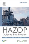
Table A3.1
Demonstration of the HAZOP study conducted on node 1 (To be used in conjunction with figure A3.1)


It will be noted that, sometimes, there are two persons in the “actions on” part of the table. This is because these two were the leaders of the discussion and are the most likely to understand the issues. The first person (initials underlined) is the one who is accountable for the action.
Please note: ″=inches.
No other meaningful parameters and deviations were found and the study of section/mode was completed.
Others to be analyzed:
Table A3.2
Demonstration of the HAZOP study conducted on node 2 (To be used in conjunction with figures A3.2 and A3.3)
It will be noted that, sometimes, there are two persons in the “actions on” part of the table. This is because these two were the leaders of the discussion and are the most likely to understand the issues. The first person (initials underlined) is the one who is accountable for the action.
The design intent is to flow five gas wells at the combined rate of 105 sm3/h (85 mmscfd) of gas from the wellhead platform, with as low sand content as practicable, into a production separator on the CPF.
The team has the following available:
• a general description of the wellhead installation and the CPF;
• the “cause and effects” drawings for the shutdown system (Tables A3.3 and A3.4, page 121);
• the operating intent from which the detailed operations are written.
The outline operating intent is as follows:
• open SSSV using methanol to form a pressure balance;
• open MV and WV the choke valve and thereby pressure up the infield pipeline monitoring for evidence of chokes/hydrates;
• slowly pressure the separator and then also the main pipeline to the shore;
Table A3.3
Cause and effects for wellhead platform
| Detected Gas (Low Level) | Detected Gas High Level 60% LEL | Detection Fire | Vibration (Impact) | |
| WVs | C | C | C | C |
| UM valves | C | C | C | |
| SSS valves | C | C | ||
| ESDV1 | C | C | ||
| ESD2 | C | |||
| C—Closed | ||||
| O—Open |

Table A3.4
| Local Fire or Gas Detected at ESDV3 and 6 | V1 High Pressure | V1 High Level | General Gas Detection High Level 60% | General Fire | |
| ESDV3 | C | ||||
| ESDV6 | C | ||||
| SD wells | C | ||||
| WV | C | C | C | C | |
| ESDV4 | C | C | C | C | |
| ESDV5 | C | C | C | C | |
| ESDV7 | C | C | O | O | |
| C—Closed | |||||
| O—Open |

The shutdown is on three levels.
Level one—process upset
Close an appropriate shutdown valve to arrest the cause of this event.
Level two—major event
In general, this means a detected fire or detected gas leakage and closes all valves around the process and blowdown all vessels—pipelines remain pressurized.
Level three—potential for major escalation
The SSSV on the wellhead platform can be closed by a manual signal from the control center on the central platform.
The riser ESD valves on the wellhead platform are closed by a manual signal from the control center on the central platform.
The riser ESD valves on the central platform are closed by fire or high-level gas detection local to the valve or by a manual signal from the control center.
Failure mode
All valves are controlled by hydraulic power (not air) and all fail closed except for the blowdown valve ESDV7 which fails open.
Piping code (for Figures A3.1–A3.3)
C—condensate
Pipe sizes are in inches
Pressure rating
15—ANSI class 1500
AP1 5000—special well piping design pressure 5000 psig
Materials
See also the cause and effects tables (Tables A3.3 and A3.4).