
6
Voice Evolution
Harri Holma and Karri Ranta-aho
6.1 Introduction
Circuit Switched (CS) voice was part of the WCDMA offering from Day 1 together with the Packet Switched (PS) data service. WCDMA voice uses Adaptive Multirate (AMR) codec with a data rate of 12.2 kbps. In many developed countries more than 50% of mobile voice minutes are now carried by WCDMA CS voice. The voice is still important from the operator revenue point of view even if data traffic is far higher than voice from the volume point of view. The voice service keeps improving further: AMR wideband (AMR-WB) offers High Definition (HD) quality, lower rate AMR improves voice capacity, voice-over HSPA provides both VoIP and CS voice capability, CS fallback from LTE to WCDMA CS voice enables voice services for LTE smartphones, and Single Radio Voice Call Continuity (SRVCC) brings handover from VoIP to CS voice. These evolution steps are summarized in Figure 6.1 and described in more detail in this chapter.
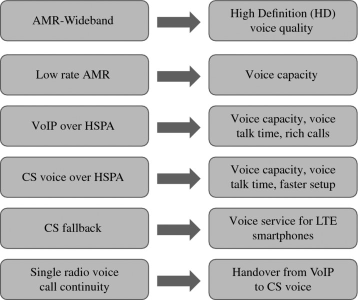
Figure 6.1 Voice enhancement options in WCDMA/HSPA
6.2 Voice Quality with AMR Wideband
AMR Wideband (AMR-WB) enhances voice quality by a higher voice sampling rate in voice encoding. AMR Narrowband (AMR-NB) uses an 8 kHz sampling rate which enables an audio bandwidth of 300–3400 Hz, similar to traditional landline phones. AMR-WB uses 16 kHz which increases the audio bandwidth to 50–7000 Hz. Voice sounds substantially better when the low and high frequencies are reproduced. The audio bandwidth is illustrated in Figure 6.2.
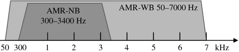
Figure 6.2 AMR-NB and AMR-WB audio bandwidth
AMR-WB codec can use data rates between 6.6 kbps and 23.85 kbps depending on the compression level. The higher data rate gives slightly better voice quality while the low data rates provide higher voice capacity. The typical data rate is 12.65 kbps, which implies that AMR-WB does not consume more capacity than AMR-NB: wideband audio with narrowband radio. AMR-WB also supports voice activity detection and discontinuous transmission to minimize the average data rate. All AMR-WB data rates and the subset with Spreading Factor (SF) 128 are shown in Figure 6.3. If we use higher than 12.65 kbps, the spreading factor needs to be 64, which means double spreading code consumption compared to SF 128.
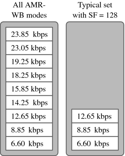
Figure 6.3 AMR-WB data rates
Voice quality with AMR-NB and AMR-WB with different data rates is shown in Figure 6.4. The quality is shown as the Mean Opinion Score where a high number indicates better voice quality. Comparing narrowband and wideband codecs with the same MOS scale is controversial, but the aim is to illustrate the major benefit of the wideband codec from the customer perspective. AMR-WB can provide MOS of 4.0 while AMR-NB has a maximum MOS of 3.2. AMR-WB with 8.85 kbps offers higher MOS than AMR-NB 12.2 kbps. AMR-WB can provide both quality and capacity benefits. AMR-WB brings very good quality already with a data rate of 12.65 kbps, which means no additional radio capacity utilized compared to the typical AMR-NB 12.2 kbps.
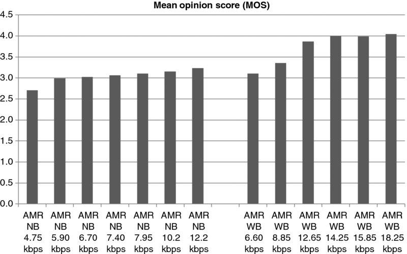
Figure 6.4 Voice quality with AMR-NB and AMR-WB
The better voice quality with AMR-WB requires that both parties have an AMR-WB-capable phone. Therefore, the higher quality will only come when AMR-WB terminal penetration increases. AMR-WB terminal penetration is increasing rapidly since most of the new smartphones have AMR-WB capability.
The AMR adaptation algorithms and benefits are described in more detail in [1].
6.3 Voice Capacity with Low Rate AMR
The AMR data rate can be modified by the radio network according to the capacity requirements. AMR-NB data rate adaptation is supported by all terminals. The typical data rate options are shown in Figure 6.5. There is a total of eight modes defined while four modes are used with SF 128 and two modes with SF 256. The number of available spreading codes is equal to the spreading factor and SF 256 helps to increase the spreading code capacity.
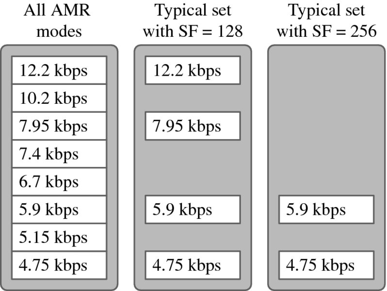
Figure 6.5 AMR-NB data rates
The uplink capacity benefit in the measurements with lower AMR rate is illustrated in Figure 6.6 with AMR 12.2 kbps and AMR 5.9 kbps. The fractional loading of a single cell is shown as a function of the number of users. For example, with 30 users the fractional loading is reduced from 20 to 13% with the lower AMR rate, which translates into +54% voice capacity improvement. The lower AMR rates lead to lower voice quality. Therefore, a preferred implementation uses high AMR rates during low load and adaptively selects lower AMR rates when the cell is congested. Similar adaptation and capacity benefit can be applied for AMR-WB as well.
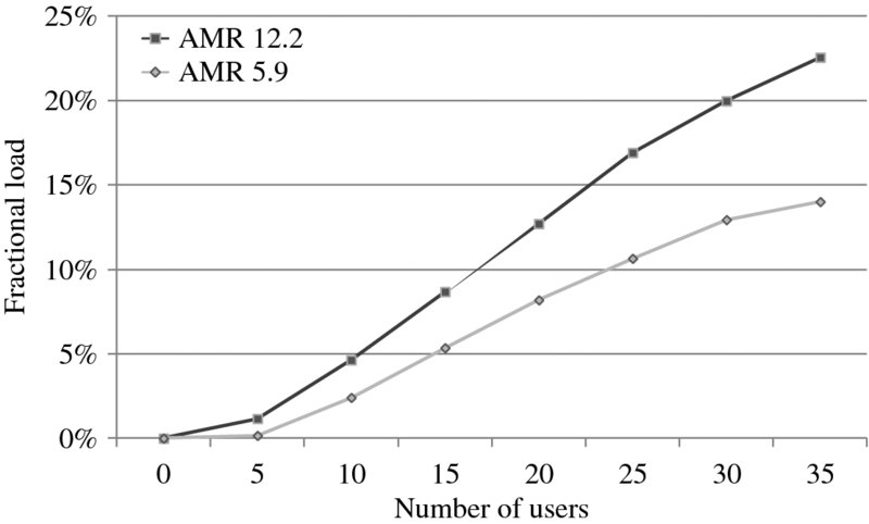
Figure 6.6 Measured uplink fractional loading with AMR12.2 and 5.9 kbps
The measurements from Figure 6.7 can be used to estimate the maximum cell capacity. Figure 6.7 shows the estimated capacity per cell both in an isolated cell and in the case of continuous coverage by assuming an inter-cell interference ratio of 0.65. The capacity of AMR5.9 can be more than 100 simultaneous users. The practical capacity may be lower due to simultaneous data and signaling traffic.
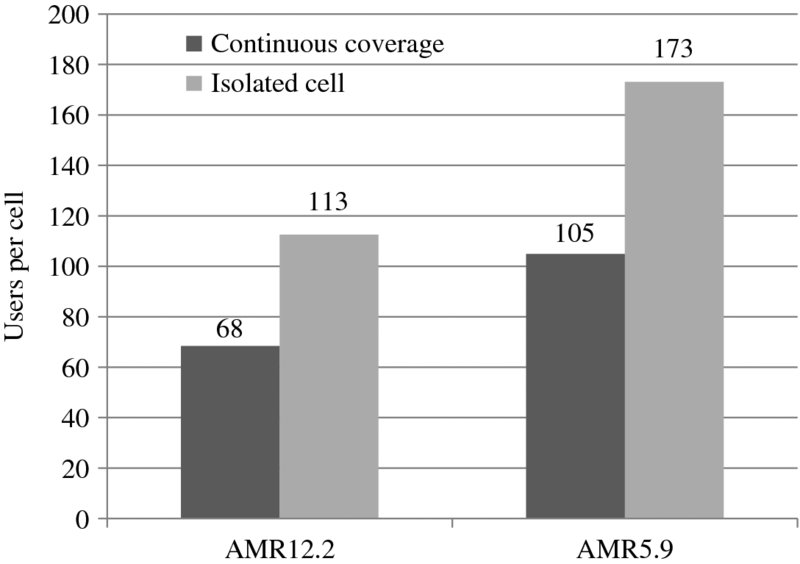
Figure 6.7 Estimated capacity with 75% uplink loading
6.4 VoIP Over HSPA
Voice traffic, both AMR-NB and AMR-WB, has been carried on a Release 99 dedicated channel (DCH). Another option is to run voice over High Speed Downlink Packet Access (HSDPA) and High Speed Uplink Packet Access (HSUPA). Release 7 introduced features that make VoIP practical over HSPA. The main features required for efficient VoIP over HSPA are as follows:
3GPP Release 4
- – Robust Header Compression (ROHC).
3GPP Release 5
- – High speed downlink packet access (HSDPA).
- – Code multiplexing of several parallel users, thus supporting multiple simultaneous low data rate connections.
- – Quality of service (QoS) differentiation parameters.
3GPP Release 6
- – High speed uplink packet access (HSUPA).
- – Non-scheduled HSUPA transmission to provide guaranteed bit rate and to minimize allocation signaling.
- – Fractional DPCH for HSDPA for minimizing the downlink L1 control overhead for low data rates.
3GPP Release 7
- – Uplink DTX for HSUPA for minimizing the L1 control overhead for low data rates. Uplink gating also minimizes UE power consumption.
- – Uplink packet bundling for minimizing the control overhead when sending two VoIP packets together.
- – Discontinuous HSDPA reception for lower UE power consumption.
- – HS-SCCH-less HSDPA for reduced downlink L1 control overhead.
The size of a full IPv6 header together with a RTP/UDP header is 60 bytes while the size of a typical voice packet is 30 bytes. Without header compression 2/3 of the transmission would be just headers. IP header compression can be applied to considerably improve the efficiency of VoIP traffic in HSPA. We assume robust header compression (ROHC) which is able to minimize the size of the headers down to a few bytes. Figure 6.8 illustrates the required data rate with full headers and with compressed headers. The required data rate is reduced from close to 40 kbps down to below 16 kbps.
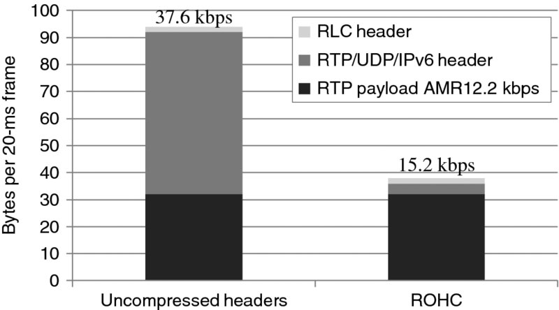
Figure 6.8 Impact of Robust Header Compression (ROHC)
The header compression with HSPA is done on Layer 2 PDCP (Packet Data Convergence Protocol) in UE and in RNC, therefore it saves not only the air interface capacity but also the Iub transmission capacity. The header compression location is illustrated in Figure 6.9.
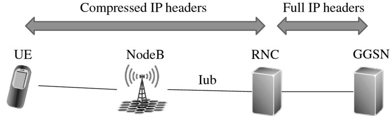
Figure 6.9 IP header compression between UE and RNC
The main motivations for using VoIP instead of CS voice are:
- – New services. When voice runs on IP, it makes the integration of rich call services simpler.
- – LTE interworking: voice in LTE must be VoIP. If also 3G networks support VoIP, the interworking between 3G and LTE is simpler.
- – Higher spectral efficiency: voice over HSPA can support more users than voice over Release 99 DCH.
- – Longer talk time: discontinuous transmission and reception reduces UE power consumption.
- – Faster call setup: when signaling runs on top of HSPA, it becomes faster.
We will consider two topics in more detail: spectral efficiency and talk time of voice over HSPA. HSPA improves the efficiency of data transmission considerably due to advanced features. The same features can also help in voice efficiency:
- – UE equalizer can remove intra-cell interference. An equalizer is included in practice in all HSPA receivers but not in WCDMA receivers.
- – UE inter-cell interference cancellation also known as the Type 3i receiver.
- – Layer 1 retransmissions can also be applied to voice, even if the delay budget is limited, since the retransmission delay is only 16 ms.
- – HSDPA fast scheduling allows improvement in efficiency even with tough delay requirements.
- – Optimized Layer 1 control channel reduces control channel overhead. The downlink solution is fractional DPCH and HS-SCCH-less transmission, and the uplink solution is discontinuous transmission.
- – Uplink interference cancellation, which is typically implemented only for HSUPA, not for WCDMA.
The results of the system-level simulations are shown in Figure 6.10. Voice over HSPA can provide up to 80–90% capacity benefit when all HSPA optimization features are included. These capacities are assumed to be uplink limited. The detailed simulation results are presented in [2–4].
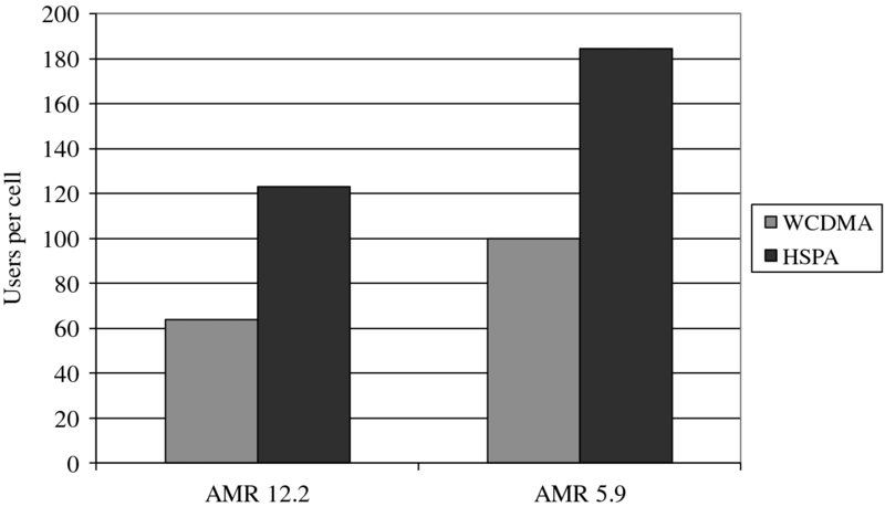
Figure 6.10 Capacity benefit of voice over HSPA
UE power consumption will benefit from running voice over HSPA. WCDMA uses continuous transmission and reception regardless of the voice activity. Voice over HSPA can utilize discontinuous transmission (DTX) and discontinuous reception (DRX). These functionalities are explained in more detail in Chapter 4. The most efficient approach to minimize power consumption is DTX and DRX. That also explains why GSM terminals tend to have longer talk times than WCDMA terminals: GSM can use DTX and DRX while WCDMA cannot.
The power consumption improvements can be estimated from the required transmission and reception activities. The estimated RF activity factors are shown in Table 6.1 for three different cases: uplink voice while downlink is silent, downlink voice while uplink is silent, and silence in both directions. The uplink activity is lower than the downlink because the downlink reception is needed for the reception of the uplink power control commands. We assume that voice transmission in downlink has 45% probability, voice in uplink 45% probability, and silence 10% probability. The average activity factors are 24% in uplink and 47% in downlink. The radio modem can utilize the inactivity periods for power savings. These activity factors assume that each voice packet is transmitted separately. The RF activity can be further reduced by using packet bundling, where two voice packets are sent together over the air interface. The activity factors with power bundling are shown in Table 6.2. If voice over HSPA were used, the power consumption could potentially be 50% lower, providing up to two times longer talk time.
Table 6.1 Voice over HSPA RF activity factors. Adapted from Holma and Toskala, 2010 [5]
| HSPA | Uplink (%) | Downlink (%) | Probability (%) |
| Uplink voice, downlink silent | 26 | 46 | 45 |
| Downlink voice, uplink silent | 26 | 52 | 45 |
| Silent both directions | 6 | 26 | 10 |
| Average activity | 24 | 47 |
Table 6.2 Voice over HSPA RF activity factors with packet bundling. Adapted from Holma and Toskala, 2010 [5]
| HSPA | Uplink (%) | Downlink (%) | Probability (%) |
| Uplink voice, downlink silent | 14 | 40 | 45 |
| Downlink voice, uplink silent | 15 | 27 | 45 |
| Silent both directions | 6 | 26 | 10 |
| Average activity | 14 | 33 |
6.5 Circuit-Switched Voice Over HSPA
Voice over HSPA was defined in 3GPP Release 7 for Voice over IP (VoIP). The rollout of VoIP service in the mobile networks happened only later, together with LTE. Therefore, Release 8 included also Circuit-Switched (CS) voice over HSPA. The CS over HSPA was a simple definition in 3GPP because it combines VoIP over HSPA in the radio network and CS voice in the core network. The high level view is shown in Figure 6.11. From the core network point of view, there is no difference between CS over WCDMA and CS over HSPA. Actually, the core network cannot even see if the radio network uses WCDMA or HSPA channels.
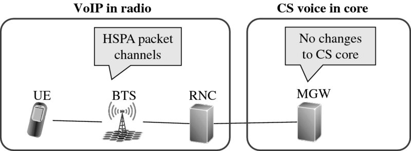
Figure 6.11 CS over HSPA uses VoIP in the radio and CS voice in the core network
The CS over HSPA radio network solution is similar to VoIP over HSPA. Both use HS-DSCH in downlink, E-DCH in uplink for carrying the voice packets, and Unacknowledged RLC mode. The minor differences come in the Packet Data Convergence Protocol (PDCP) layer where VoIP uses header compression which is not needed in CS voice. On the other hand, CS voice uses a dejitter buffer in the RNC to keep the packet transmission timings to the core network fixed. The dejitter buffer in the case of VoIP is located in the other terminal, not in the radio network. The large similarities between CS and VoIP over HSPA also make practical implementation simpler. The three different voice solutions are compared in Figure 6.12.
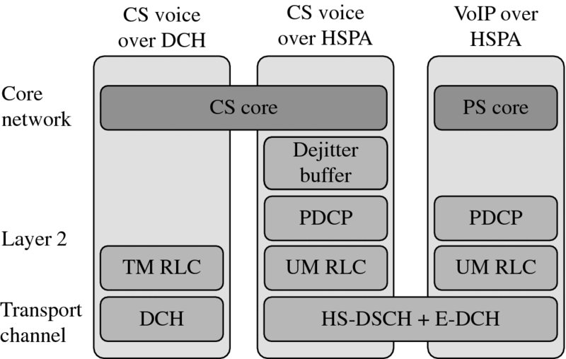
Figure 6.12 CS over HSPA in the radio network (TM = Transparent Mode. UM = Unacknowledged Mode)
The multiplexing of data and voice transmissions in the radio network is illustrated in Figure 6.13. The CS voice is carried over Iu-CS while VoIP and packet data is carried over Iu-PS. AMR data rate adaptation is selected in RNC according to the radio network loading. Release 99 channels are allocated in RNC. All the HSPA transmissions including CS voice, VoIP, and packet data, are multiplexed by NodeB taking into account the latency requirements. Voice packets are transmitted with higher priority compared to the data packets.
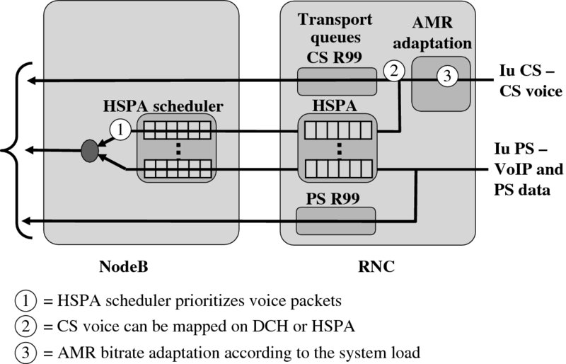
Figure 6.13 Multiplexing of voice and data transmissions
CS voice over HSPA has not yet been commercially deployed in 2014. One reason is that CPC functionality is needed first and that was only properly tested and optimized during 2013. Another reason is that the data traffic takes most of the capacity and the voice traffic eats only small fraction of the network capacity. Therefore, the capacity gain provided by CS voice over HSPA is less relevant when data traffic is booming.
6.6 Voice Over HSPA Mobility
Mobility on dedicated channels relies on soft handover, while HSDPA does not use soft handover. This section explains the mobility solution for HSDPA. The procedure is shown in Figure 6.14. We consider both procedural delay and voice interruption time in the user plane. The procedural delay is relevant for mobility reliability while the user plane break is important for voice quality. First, the new target cell emerges and enters the reporting range in UE at time t1. Some delay is caused by the UE measurement averaging, which is at least 200 ms. When the reporting trigger is fulfilled, UE sends a measurement report on the signaling radio bearer at time t2. The serving RNC reserves the base station and Iub resources to the target NodeB #2. Once the resources are ready at time t3, the RNC sends a radio bearer reconfiguration message to the UE, which still keeps receiving data from the source NodeB #1. When the UE has decoded the reconfiguration message and the activation time has expired at time t4, the UE will move the reception from the source cell to the target cell. This case is called synchronous procedure. Another option is asynchronous procedure, where the activation of the reconfiguration message is immediate and the activation time is now. The UE specific MAC-hs in the source cell is reset at the time of the cell change and the buffered PDUs are deleted. At the same time, the flow control unit in the MAC-hs in the target cell starts to request PDUs from the serving RNC, so that it can start to transmit data on the HS-DSCH to the user. It is also possible for the RNC to send duplicate transmissions of the packet to both NodeBs during the cell change. When the RNC receives the Reconfiguration Complete message from the UE, it can release the resources from the source cell. The total procedural delay from t1 to t4 is mainly dominated by the measurement delay from t1 to t2. The critical factor is that UE must receive the reconfiguration command before the downlink radio link deteriorates too much due to signal fading or inter-cell interference.
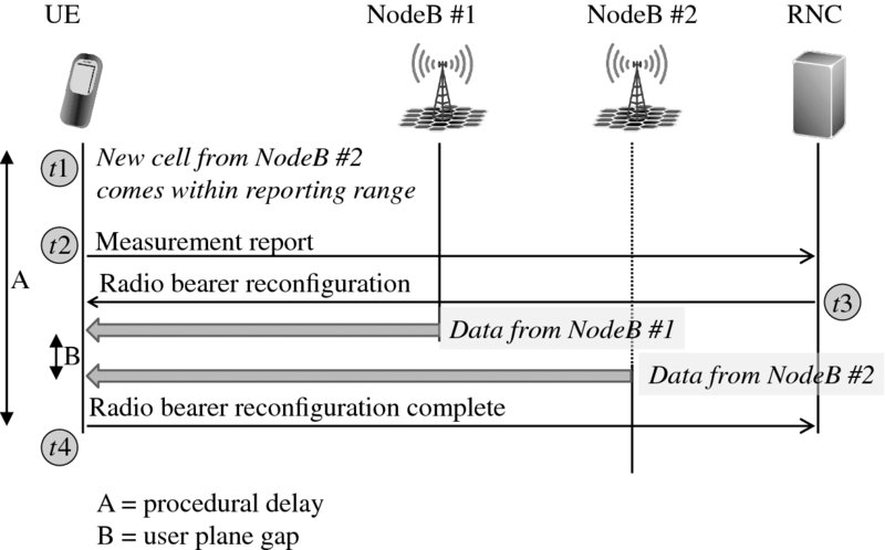
Figure 6.14 Mobility procedure on HSDPA
The transmission gap, denoted as the time B in Figure 6.14, can be very low since the UE makes the cell change synchronously with the network, switching the transmission from the source cell to the target cell. The break can be squeezed down to a few tens of ms and almost completely eliminated with bicasting the voice packets to both NodeBs during the mobility procedure.
A few enhancements can be applied to further improve the mobility: re-establishment and enhanced serving cell change with bicasting. Re-establishment works as follows: if the radio link fails, UE sends a cell update message to the new target cell. RNC will then re-establish a new radio link to the UE and continue the voice connection. There is a break of a few seconds in the voice communication in this procedure. The voice break is mainly caused by the radio link time-out timer. The major benefit of re-establishment is that call drops can be avoided. Re-establishment is widely used for Release 99 voice channels.
Enhanced serving cell change can improve the mobility reliability because UE can switch to the new target cell immediately after sending the measurement reporting without waiting for the reconfiguration command from RNC. The fast switching can avoid radio link failure in downlink that may happen while UE waits for the reconfiguration command. The procedure is shown in Figure 6.15. UE starts to monitor HS-SCCH from NodeB #2 after sending the measurement report. UE still receives data from NodeB #1. The HS-SCCH code has been indicated to UE earlier for all those cells that are in the active set. When the NodeB #2 gets the handover information from RNC, it indicates the servicing cell change to UE on HS-SCCH order. When UE receives the cell change order on HS-SCCH, it changes the data reception to NodeB #2 and sends a reconfiguration complete message to RNC. The user plane break can be minimized by using bicasting where RNC sends the same data to both NodeBs after receiving the measurement report.
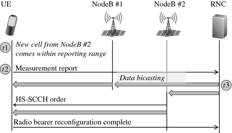
Figure 6.15 Enhanced serving cell change
6.7 Circuit-Switched Fallback
All LTE smartphones need a voice solution. Voice over LTE (VoLTE) is the long-term solution but has not yet been widely deployed. Most of the initial LTE smartphones use WCDMA or GSM networks for carrying the voice as traditional CS voice while LTE is used only for data transmission. This solution is called CS fallback handover. UE normally camps in the LTE network in order to provide access to LTE data rates. The paging message of the mobile terminating call is transmitted from the Mobile Switching Center Server (MSC-S) to the Mobility Management Entity (MME) and further to UE. When UE responds to the paging message, the LTE network commands UE to move to WCDMA or GSM network for the voice call. The UE can be moved by redirection or by handover. When the voice call is over, UE returns to the LTE network by reselection or by redirection. If there is a data connection running in LTE, the data is handed over to WCDMA or GSM during the voice call. That means data connection also continues during the voice call but the LTE data rates are not available, only HSPA or EDGE data rates. The overview of CS fallback handover is shown in Figure 6.16. For more details about LTE interworking see Chapter 15.
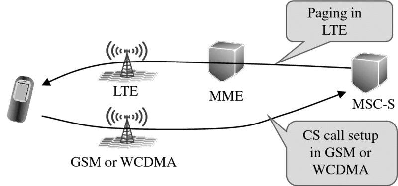
Figure 6.16 CS fallback handover from LTE to GSM/WCDMA
CS fallback has turned out to perform well in live networks. Some optimization steps have been implemented in order to minimize the call setup time and to minimize the return time back to LTE. The main solutions for minimizing the call setup time are
- – Skipping the reading of the System Information Block (SIB) in the target system.
- – Avoiding Location Area Update (LAU) in the target system.
SIB reading can be avoided by providing the target cell SIB via LTE the network or providing the SIB only after the call setup in the target system. UE may also store the target system SIB if CS fallback happens multiple times to the same cell. LAU can be avoided in the call setup by configuring the core network so that the same location area code is used by the target MSC and the MSC where the paging is coming from. With optimized CS fallback procedure the additional call setup time can be below 1 s, which makes CS fallback performance in practice nearly as good as any WCDMA or GSM call.
The delay in getting UE back to LTE after the CS call can be minimized by using network controlled redirection after the voice call to push UE back to the LTE network. The initial solution used UE based reselection, which can cause 10 s or more delay when returning to LTE. When the redirection is implemented to the networks, the UE can instantaneously return to LTE after the voice call.
GSM/WCDMA operators can select the target network to be either WCDMA or GSM. Most operators use WCDMA as the CS fallback target. The call setup time is lowest when the CS fallback is to WCDMA. Many WCDMA networks also use AMR-WB for the best voice quality. All WCDMA networks and UEs also support simultaneous voice and data transmission. The network configuration for CS fallback to WCDMA is also simpler since only the target frequency needs to be given to the UE. Some operators use GSM as the target network, mainly if the WCDMA network does not provide full coverage. The target system can also be selected based on UE measurements: CSFB to WCDMA if the coverage is available.
6.8 Single Radio Voice Call Continuity
There may be a need to make a handover from VoIP to CS voice due to mobility. The typical use case is handover from Voice over LTE (VoLTE) to CS voice in WCDMA when UE runs out of LTE coverage area and there is no VoIP support in HSPA network. The handover functionality from VoIP to CS domain is referred to as Single Radio Voice Call Continuity (SRVCC). The solution does not require UE capability to simultaneously signal on two different radio access technologies – therefore it is called the single radio solution.
LTE eNodeB first triggers the UE to start inter-system measurements of the target WCDMA system and receives the measurement report. eNodeB then sends the handover request to MME, which triggers the SRVCC procedure via Sv interface to MSC-Server. Sv is a new interface between MSC server and MME. The resources in the target cell are reserved and the necessary information is provided for the UE via LTE access. When the SRVCC procedure has been completed successfully, then VoIP connection remains from MSC towards the other side of the ongoing session. The CS connection exists towards the WCDMA radio access network. SRVCC architecture is shown in Figure 6.17.
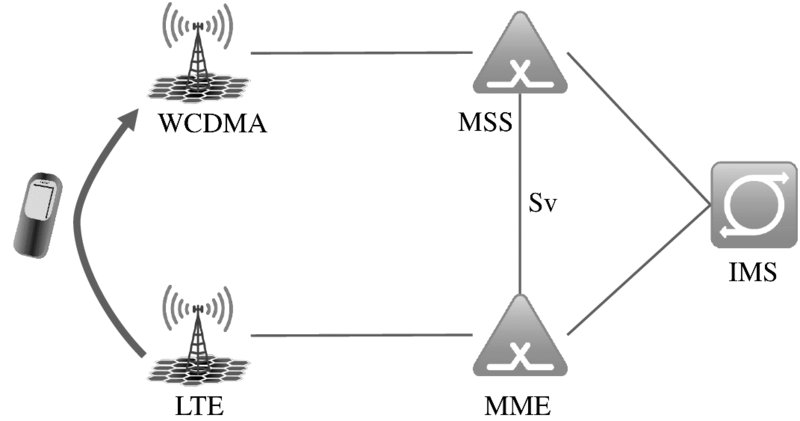
Figure 6.17 Single Radio Voice Call Continuity (SRVCC) from LTE to WCDMA
In the case of simultaneous voice and non-voice data connection, the handling of the non-voice bearer is done by the bearer splitting function in the MME. The process is done in the same way as the normal inter-system handover for packet services.
In the case of roaming, the Visited PLMN controls the radio access and domain change while taking into account any related Home PLMN policies.
6.9 Summary
The WCDMA/HSPA system offers a comprehensive set of voice services. CS voice over WCDMA dedicated channels have been the baseline voice solution. Voice quality can be enhanced with AMR-Wideband codec and voice capacity can be improved with AMR-Narrowband lower codec rates. The voice service can also be provided over HSPA channels both as VoIP and as CS voice. The initial LTE smartphones typically use WCDMA CS voice with CS fallback functionality. When voice over LTE service is started, it can be complemented with the handover from VoLTE to WCDMA CS voice, called SRVCC.
References
- Holma, H., Melero, J., Vainio, J. et al. “Performance of Adaptive Multirate (AMR) Voice in GSM and WCDMA”, VTC 2003.
- Holma, H., Kuusela, M., Malkamäki, E. et al. “VoIP over HSPA with 3GPP Release 7”, PIMRC 2006, September 2006.
- 3GPP Technical Report 25.903 “Continuous connectivity for packet data users”, v. 7.0.0, 2007.
- NSN White paper “Long Term HSPA Evolution meets ITU IMT-Advanced requirements”, 2012.
- Holma, H. and Toskala, A. (2010) WCDMA for UMTS – HSPA Evolution and LTE, 5th edn, John Wiley & Sons, Ltd, Chichester.