
3
Basic Hacks
This chapter contains a set of fairly basic “hacking” how-tos. These build and use various electronic construction techniques. So this is probably a good chapter to at least skim through so that when you attempt more advanced how-tos, you can refer back to it if needed.
How to Make a Resistor Get Hot
Sometimes things will get hot when you are hacking electronics. It’s always better when this is expected rather than when it’s a surprise, so it’s worth doing a little experimenting in this area.
You Will Need
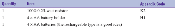
Figure 3-1 shows the schematic diagram.
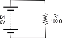
FIGURE 3-1 The schematic for heating a resistor
The Experiment
All we will do is connect the 100Ω resistor across the battery terminals and see how hot it gets.
 |
Be careful when doing this because the resistor’s temperature will rise to about 50°C/122°F. The resistor’s leads, however, will not get very hot. |
We are using a battery holder that takes four AA cells, each providing about 1.5V. They are each connected, one after the other, providing us with 6V total. Figure 3-2 shows how the batteries are actually connected within the battery box as a schematic diagram. In this kind of arrangement, the batteries are said to be in series.
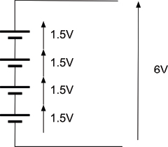
FIGURE 3-2 The schematic diagram for a battery holder
Figure 3-3 shows the resistor heater in action.
FIGURE 3-3 Making a resistor get hot
Simply touch a finger to the resistor to confirm it’s hot.
Is this bad/good? Will the resistor eventually break because it’s warm? No, it won’t. Resistors are designed to cope with a bit of heat. If we do the math, the power that the resistor is burning is the voltage squared divided by the resistance, which is:
(6 × 6) / 100 = 0.36W
If it is a 0.25-W resistor, then we are exceeding its maximum power. This would be a foolish thing to do if we were designing a product for mass production. However, that’s not what we are doing, and the chances are the resistor would continue to work like that indefinitely.
How to Use Resistors to Divide a Voltage
Sometimes voltages are too big. For example, in an FM radio, the signal going from the radio part to the audio amplifier part will be deliberately too large so it can be reduced using the volume knob.
Another example might be when you have a sensor that produces a voltage between 0 and 10V but you want to connect it to an Arduino microcontroller that expects it to be between 0 and 5V.
A very common technique in electronics is to use a pair of resistors (or a single variable resistor) as a “voltage divider.”
You Will Need
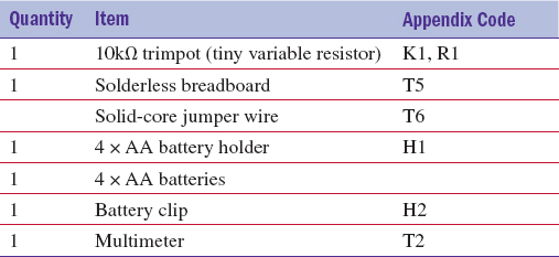
Figure 3-4 shows the schematic diagram for our experiment. There are a couple of new schematic symbols here. The first is the variable resistor (or pot). This looks like a regular resistor symbol, but has a line with an arrow connecting to the resistor. This is the moving slider connection of the variable resistor.
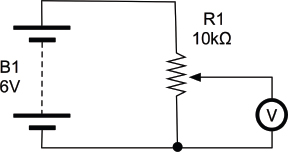
FIGURE 3-4 A voltage divider schematic diagram
The second new symbol is the circle with a “V” in it. This is a voltmeter, which in our case is the multimeter set to its DC voltage range.
The variable resistor we will use has three leads. One lead is fixed at each end of a conductive track, while a third connection to the central slider moves from one end of the track to the other. The overall resistance of the whole track is 10kΩ.
Our voltage in is going to be supplied from the battery pack and will be roughly 6V. We are going to use a multimeter to measure the output voltage and see how much it is being reduced by our voltage divider.
If you remember, the grey bars indicate where the connections underneath the holes are connected together. Take some time to follow the lines on the stripboard and reassure yourself that everything is connected in the same way as the schematic (Figure 3-4).
Plug the trimpot into the breadboard as shown, and then wire up the battery by carefully pushing the leads into the + and – power supply lines on the breadboard: red to +, black to –. If you struggle to get the multi-core wires of the battery clip into the holes, solder a bit of solid-core wire to the end of the leads.
Attach wires between the positive supply and the top connection of the trimpot, and the negative supply and the bottom connection of the trimpot. Finally, attach the multimeter. If your multimeter has alligator clips, use these in preference to the normal probes, clipping short jumper wires into the alligator clips and then pushing the other ends into the positions shown in Figure 3-5. When you have done all this, your breadboard should look something like Figures 3-6a and 3-6b.
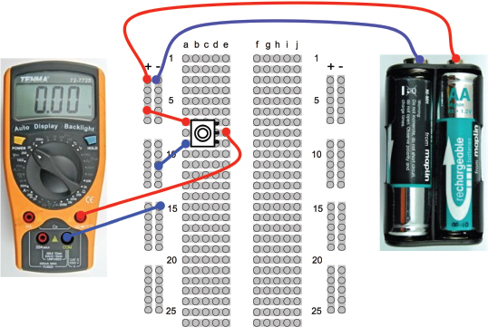
FIGURE 3-5 A voltage divider breadboard layout
FIGURE 3-6 A voltage divider breadboard
Turn the trimpot to its fully clockwise position. The multimeter should read 0V (Figure 3-6a). Now turn it fully anti-clockwise and it should read something around 6V (Figure 3-6b)—in other words, the full battery voltage. Finally, turn it to roughly the middle position and you should see that the meter indicates about 3V (Figure 3-6c).
Think of the variable resistor as behaving a bit like two resistors, R1 and R2, as shown in Figure 3-7.
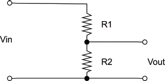
FIGURE 3-7 A voltage divider with fixed resistors
The formula to calculate Vout if we know Vin, R1 and R2 is as follows:
Vout = Vin * R2 / (R1 + R2)
So, if R1 and R2 are both 5 kΩ and Vin is 6V, then:
Vout = 6V * 5kΩ / (5kΩ + 5kΩ) = 30 / 10 = 3V
This ties in with what we found when we put the trimpot to its middle position. It is exactly the same as having two fixed resistors of 5 kΩ each.
As with many of the calculations you make in electronics, people have made handy calculating tools. If you type “voltage divider calculator” into a search engine, you will find them. One such example can be found here: www.electronics2000.co.uk/calc/potential-divider-calculator.php.
These calculators will also usually match to the nearest available fixed resistor value.
How to Convert a Resistance to a Voltage (and Make a Light Meter)
An LDR (light-dependent resistor; a.k.a., photoresistor) is a resistor whose resistance changes depending on the amount of light falling on its transparent window. We will use one of these devices to demonstrate the idea of converting a resistance to a voltage by using it as one-half of a potential divider.
You Will Need
Before we get the breadboard out, let’s just experiment directly with the LDR. Figure 3-8 shows the LDR connected directly to the multimeter on its 20kΩ resistance setting. As you can see, the resistance of my LDR was 1.07kΩ. Putting my hand over the LDR to screen out some of the light increased that resistance to a few tens of kΩ. So, the way the LDR works, the more light that reaches it, the lower the resistance.
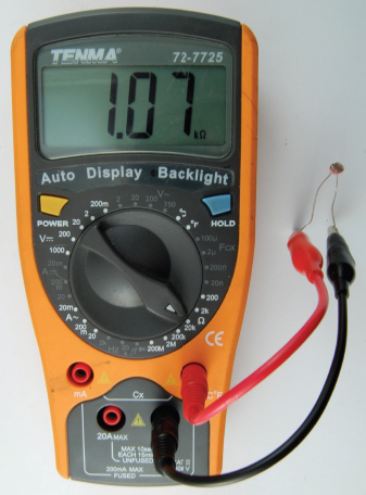
FIGURE 3-8 Measuring the LDR resistance
Microcontrollers such as the Arduino can measure voltages and do things with them, but not directly measure resistance. So to convert our LDR’s resistance into a more easily used voltage, we can put it in a voltage divider as one of the resistors (Figure 3-9).
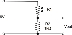
FIGURE 3-9 Measuring light level with an LDR and voltage divider
Note that the symbol for the LDR is like a resistor but with little arrows pointing to it to indicate its sensitivity to light.
We can make up this schematic on our breadboard, this time setting our multimeter to the 20V DC range and watching how the voltage changes as we cover the LDR to reduce the light getting to it (Figures 3-10 and 3-11).
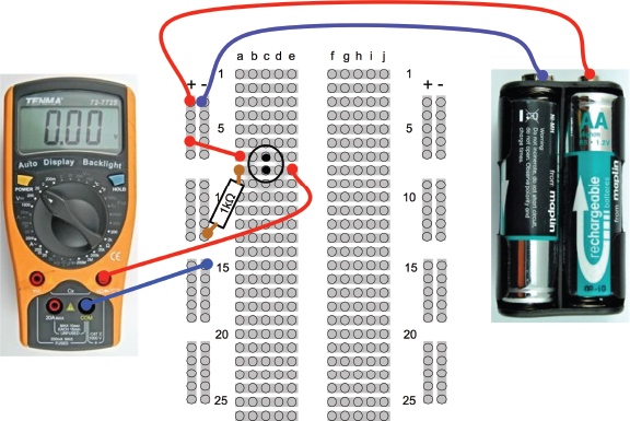
FIGURE 3-10 A breadboard layout for light measurement
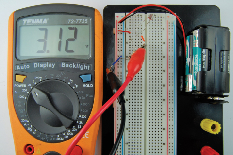
FIGURE 3-11 Light measurement
Hack a Push Light to Make It Light Sensing
Battery-powered push lights are one of the many glorious bargains you are likely to find in a dollar/euro/pound store. These are intended for use in cupboards and other dark locations where a bit of extra light would be useful. Push them once and they light, push them again and they turn off.
It will not surprise you to hear that we are going to use our LDR to turn the light on and off. But we are also going to use a transistor.
Our approach will be to get it working on breadboard first and then solder up the design onto the push light. In fact, we will use a single LED in place of the push lamp until we know that it will work.
You Will Need
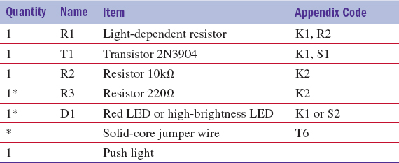
* These components are only needed for the breadboard experiment.
We want the LDR to control an LED, so a first thought at a circuit might be as shown in Figure 3-12.
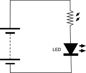
FIGURE 3-12 An LED and LDR
There are two fatal flaws in this design. First, as more light falls on the LDR its resistance decreases, allowing more current to flow so the LED will get brighter. This is the opposite of what we want. We want the LED to come on when it’s dark.
We need to use a transistor.
The basic operation of a transistor is shown in Figure 3-13. There are many different types of transistors, and probably the most common (and the type we will use) is called an NPN bipolar transistor.
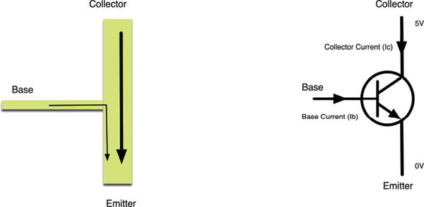
FIGURE 3-13 A bipolar transistor
This transistor has three leads: the emitter, the collector, and the base. The basic principal is that a small current flowing through the base will allow a much bigger current to flow between the collector and the emitter.
Just how much bigger the current is depends on the transistor, but it’s typically a factor of 100.
Breadboard
Figure 3-14 shows the schematic diagram we will build on the breadboard. To understand this circuit, let’s consider two cases.
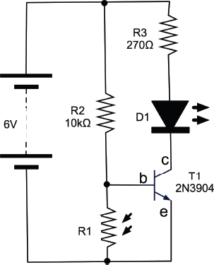
FIGURE 3-14 Using an LDR and transistor to switch an LED
Case 1: When It’s Dark
In this case, the LDR R1 will have a very high resistance, so you could almost imagine that it isn’t there at all. In that case, current will flow through R2, through the base and emitter of the transistor, allowing as much current as it needs to flow through R3, the LED, and T1 into its collector and out through the emitter. When enough current flows into the base of a transistor to allow current to flow from the collector to the emitter, this is called “turning on” the transistor.
We can calculate the base current using Ohm’s law. In this situation, the base of the transistor will be at only about half a volt, so we can assume there is more or less the full 6V across the 10kΩ resistor R2. Since I = V / R, the current will be 6 / 10,000 A or 0.6mA.
Case 2: When It’s Light
When it is light, we have to consider the resistance of the LDR R1. The lighter it is, the lower the resistance of R1 and the more of the current otherwise destined for the base of the transistor will be diverted through R1, preventing the transistor from turning on.
I think the time has come to build the project on breadboard. Figure 3-15 shows the breadboard layout, and Figures 3-16a and 3-16b the finished breadboard.
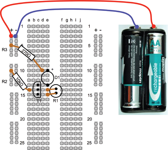
FIGURE 3-15 The light switch breadboard layout
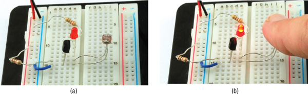
FIGURE 3-16 The light switch breadboard
When placing the LED on the breadboard, make sure you get it the right way around. The longer lead is the positive lead, and it should be on row 10 connected to R3. (See Figure 3-16a.)
If everything is fine, you should find that when you cover the LDR, the LED should light (Figure 3-16b).
Construction
Now that we have proved our circuit works, we can get on with modding the push light. Figure 3-17 shows the push light the author used. Unless you are very lucky, yours is likely to be different, so read through the following sections carefully and you should be able to work out how to change your light. To make life easy for yourself, try and find a push light that operates from 6V (4 AA or AAA cells).
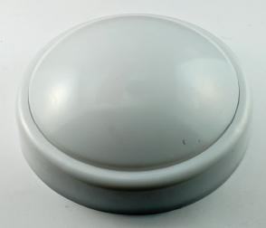
FIGURE 3-17 A push light
You will probably find screws on the back of the push light. Remove these and put them somewhere safe. The inside of the push light is shown in Figure 3-18. The various connections on the light are marked. You can find the corresponding connections on your light using a multimeter.
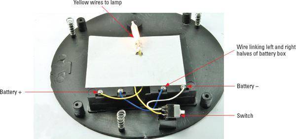
FIGURE 3-18 Inside the push light
Setting the multimeter to its 20V DC range will let you determine which battery lead is positive and which is negative. Looking at the wiring, we can draw a schematic diagram for the light as it stands, before we start altering it (Figure 3-19).
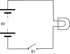
FIGURE 3-19 The schematic diagram for the original push light
This light uses an old-fashioned incandescent bulb. We will replace that with a high-brightness LED. If you don’t have one of these, a regular LED of the color of your choice will work, but not be very bright.
Figure 3-20 shows how we replaced the bulb with the LED and the 220Ω resistor. Make sure the longer positive lead of the LED is connected to the resistor and the far side of that resistor is connected to the positive terminal of the battery.
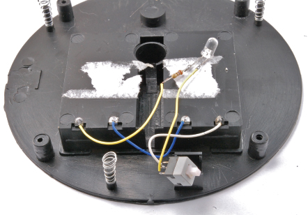
FIGURE 3-20 Replacing the bulb with an LED and a resistor
Try pressing the switch to make sure the LED is working.
We can now draw a schematic that combines what we have in the existing lamp and our LDR circuit (Figure 3-21).
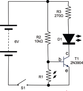
FIGURE 3-21 The final schematic
In fact, all this really amounts to is adding in the switch to the original LED schematic. We have already installed R3 and D1 when we replaced the bulb with an LED. The switch is already there, so all we need to add is the transistor, LDR, and R2. Figure 3-22 shows how we will rewire the push light.
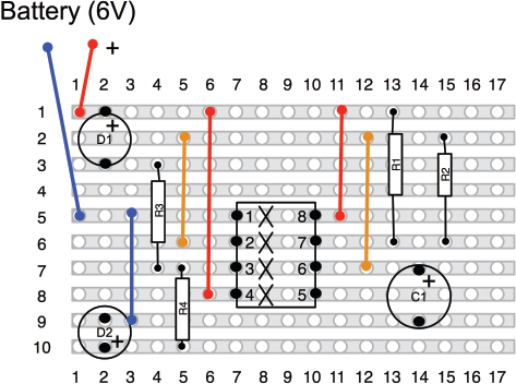
FIGURE 3-22 The push light wiring diagram
Figure 3-23 shows the sequence of steps in soldering the extra components onto the light.
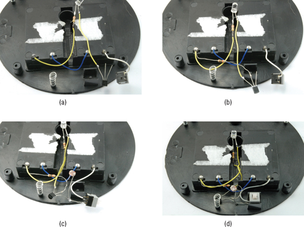
FIGURE 3-23 Soldering the project
1. Start by desoldering the lead from the switch that isn’t connected to the negative battery terminal (Figure 3-23a).
2. Solder the 10kΩ resistor R2 between the middle lead of the transistor (the base) and the positive terminal on the battery box.
3. With the flat of the transistor facing upward, as shown in the diagram, connect the left-hand lead of the transistor to the wire you just disconnected from the switch (Figure 3-23b).
4. Solder the LDR between the left and middle pins of the transistor, and connect the combined left-hand transistor lead and LDR lead to the connection on the switch that the wire used to be attached to. (See Figure 3-23c.)
5. Tuck the components away neatly, bending the leads to make sure there is no way the bare leads can touch each other. (See Figure 3-23d.)
There you are! You have hacked some electronics.
How to Choose a Bipolar Transistor
The transistor we used in the previous section, “Hack a Push Light to Make It Light Sensing,” is a useful general-purpose transistor. But there are many other types of transistors that we can use for different purposes. This section is to help you find the right transistor and try to use it in such a way that it doesn’t die in a puff of smoke.
Datasheets
Transistors have a number of parameters we need to know about. All transistors have an associated datasheet. This is produced by the manufacturer and specifies everything you could possibly want to know about the device, from the dimensions of its leads to its electrical characteristics.
Most of the time you will use one of three or four transistors and will not need to look into the exact details of how the transistor behaves, but if you do need to, it’s there on the datasheet. So, you may just want to skip to the next subsection where we look at a few different types of transistors—just the useful ones, nothing exotic.
Table 3-1 shows some of the data you will find on the 2N3904’s datasheet under maximum ratings.

TABLE 3-1 2N3904 Maximum Ratings
Maximum Collector-Emitter and Collector-Base voltages of 40V and 60V mean we do not have to worry about exceeding them in battery-powered devices. We need to be careful that we do not exceed the emitter-base voltage though.
The maximum collector current of 200mA is quite healthy though. It means we could in theory control ten LEDs, all taking 20mA at the same time. If we do exceed this value, then the transistor will get hot and eventually fail.
The one electrical characteristic we are most interested in is DC current gain or hFE as it will be called on the datasheet. This is listed in the electrical characteristics section of the datasheet.
You may remember that the DC gain is the multiplier that determines how much more current can flow in through the base than the collector. Looking at Table 3-2, this means that at a collector current of 10mA and a collector emitter voltage of 1.0V (it’s nearly always about that), the typical gain will be 100, meaning that only 10mA /100 = 100nA needs to be flowing into the base for this amount of current to flow through the collector.
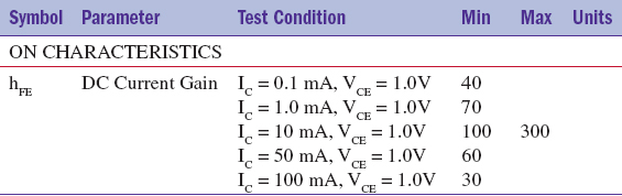
TABLE 3-2 2N3904 Electrical Characteristics
MOSFET Transistors
The 2N3904 is what is called a bipolar transistor. It’s basically a device that amplifies current. A small current into the base controls a much bigger current flowing through the collector. Sometimes, the current gain of just 100 or so is not nearly enough.
There is another type of transistor that does not suffer from this limitation called the MOSFET (Metal Oxide Semiconductor Field Effect Transistor). You can see why it gets shortened to MOSFET. These transistors are controlled by voltage rather than current and make very good switches.
MOSFETs do not have emitters, bases, and collectors, they have “sources,” “gates,” and “drains.” They turn on when the gate voltage passes a threshold, usually about 2V. Once on, quite large currents can flow through the “drain” to the “source” rather like a bipolar transistor. But since the gate is isolated from the rest of the transistor by a layer of insulating glass, hardly any current flows into the gate. It is the voltage at the gate that determines what current will flow.
We will meet MOSFETs again later in the section “How to Use a Power MOSFET to Control a Motor,” and in Chapter 7 in the section “How to Control Motor Speed with a Power MOSFET.”
PNP and N-Channel Transistors
The automated light switch of the previous section switched on the “negative side of the load.” That is, if you go back to Figure 3-21, you can see that the resistor and LED that make up the light are not connected to GND except through the transistor. If for some reason (and this does happen) we wanted to switch the positive side, then we would need to use a PNP equivalent of the NPN 2N3904, such as the 2N3906. NPN stands for Negative-Positive-Negative, and yes, you can guess what PNP stands for. That is because transistors are kind of semiconductor sandwiches, with material of either N or P type as the bread. If the bread is N type (the most common), then the base voltage needs to be higher than the emitter voltage (by about 0.5V) before the transistor starts to turn on. On the other hand, a PNP transistor turns on when the base voltage is more than 0.5V lower than the emitter voltage.
If we wanted to switch the positive side, we could use a PNP transistor (as shown in the PNP alternative to Figure 3-21) displayed in Figure 3-24.
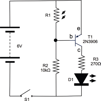
FIGURE 3-24 Using a PNP bipolar transistor
MOSFETs also have their own equivalent of PNP transistors called P-channel, their version of the more common NPN being called N-channel.
Common Transistors
The transistors in Table 3-3 will cover a wide range of transistor applications. There are thousands and thousands of other transistors, but in this book we only really use them for switching, so these will cover most “bases”!
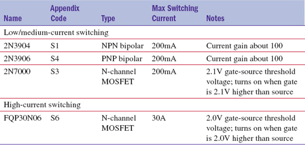
TABLE 3-3 Really Useful Transistors
How to Use a Power MOSFET to Control a Motor
Figure 3-25 shows the schematic symbol and the pinout for the FQP30N06 N-channel MOSFET.
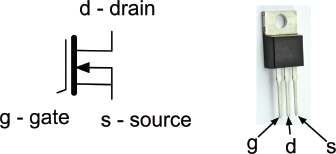
FIGURE 3-25 The FQP30N06 N-channel MOSFET
This MOSFET is capable of controlling loads of up to 30A. We are not going to push it any way near that far, we are just going to use it to control the power to a small electric motor that might have a peak load of 1 or 2A. While this would be too much for the bipolar transistors that we have been using so far, this MOSFET will hardly notice!
You Will Need
To try out this high-power MOSFET, you will need the following items.
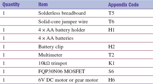
The DC motor can be any small motor you can find that is around 6V. A motor rated at 12V should still turn at 6V. To test it, just connect its terminals directly to the 6V battery.
Breadboard
The schematic diagram for what we will make is shown in Figure 3-26.
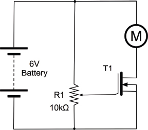
FIGURE 3-26 A schematic for the MOSFET experiment
The variable resistor will control the voltage at the gate of the MOSFET. When that gate voltage exceeds the gate threshold, the transistor will turn on and the motor will start.
The breadboard layout for the project and a photograph of the experiment in action are shown in Figure 3-27 and Figure 3-28.
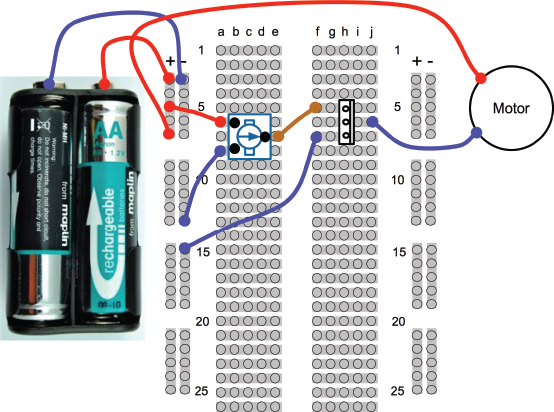
FIGURE 3-27 The breadboard layout for the MOSFET experiment
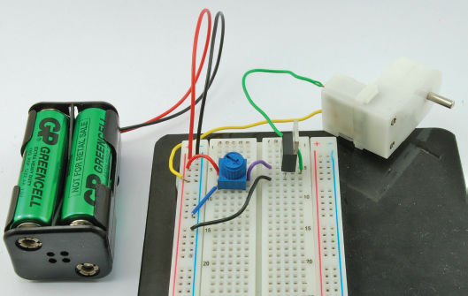
FIGURE 3-28 The MOSFET experiment
To connect the motor to the breadboard, you will probably need to solder a pair of leads to it. It does not matter which way around you connect the motor. The polarity just determines which direction the motor turns. So if you swap the motor leads over, it will turn in the opposite direction.
Try turning the knob on the variable resistor. You will see that you do not have a great deal of control over the speed of the motor. If you hover around the threshold voltage, you can control the motor speed, but you can probably see why the MOSFET is most commonly used as a switch that is either on or off.
This kind of MOSFET is called a logic level MOSFET, because its gate voltage is low enough to be controlled directly by digital output pins on a microcontroller. This is not true of all MOSFETs. Some have gate threshold voltages of 6V or more.
In Chapter 7, you will use a MOSFET to finely control the motor speed.
How to Select the Right Switch
On the face of it, a switch is a very simple thing. It closes two contacts, making a connection. Often, that is all you need, but other times you will require something more complicated. For example, let’s say you want to switch two things at the same time.
There are also switches that only make the contact while you are pressing them, or ones that latch in one position. Switches may be push button, toggle, or rotary. There are many options to choose from and in this section we will attempt to explain the options.
Figure 3-29 shows a selection of switches.
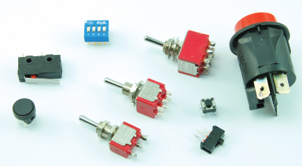
FIGURE 3-29 Switches
Push-Button Switches
Where so many things use a microcontroller, a simple push switch is probably the most common type of switch (Figure 3-30).
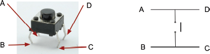
FIGURE 3-30 A push switch
This kind of switch is designed to be soldered directly onto a circuit board. It will also fit onto our breadboard, which makes it quite handy.
The confusing thing about this switch is that it has four connections where you would only expect there to be two. Looking at Figure 3-30, you can see that connections B and C are always connected together, as are A and D. However, when the button is pressed, all four pins are all connected together.
This does mean that you need to be careful to find the right pins or your switch will be connected all the time.
If there is any doubt about how the switch works, use your multimeter set to Continuity mode to work out what is connected to what—first without the switch pressed and then with the switch pressed.
Microswitches
A microswitch is another type of handy switch. They are not designed to be pressed directly, but are often used in things like microwave ovens to detect that the door is closed, or as anti-tamper switches that detect when the cover is removed from an intruder alarm box.
Figure 3-31 shows a microswitch—with three pins!
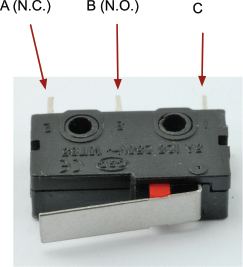
FIGURE 3-31 A microswitch
The reason a microswitch has three pins rather than just two is that it is what is known as a “double throw” or “change-over” switch. In other words, there is one common connection C and two other connections. The common connection will always be connected to one of those contacts, but never both at the same time. The normally open (n.o.) connection is only closed when the button is pressed; however, the normally closed (n.c.) connection is normally closed, and only opens when the button is released.
If you have one of these switches, you might like to connect your multimeter to it. Attach one lead to the common connection and use it to find the n.c. connection, then press the button and the beep should stop.
Toggle Switches
If you look through a component catalog (which every good electronics hacker should), you will find a bewildering array of toggle switches. Some will be described as DPDT, SPDT, SPST, or SPST, momentary on, and so forth.
Let’s untangle some of this jargon, with a key for these cryptic letters:
• D = Double
• S = Single
• P = Pole
• T = Throw
So, a DPDT switch is double pole, double throw. The word “pole” refers to the number of separate switch contacts that are controlled from the one mechanical lever. So, a double pole switch can switch two things on and off independently. A single throw switch can only open or close a contact (or two contacts if it is double pole). However, a double throw switch can make the common contact be connected to one of two other contacts. So, a microswitch is a double throw switch because it has both normally closed and normally open contacts.
Figure 3-32 summarizes this.
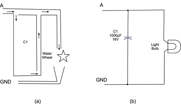
FIGURE 3-32 Toggle switches— poles and throws
Notice in Figure 3-32 that when drawing a schematic with a double pole switch, it is normal to draw the switch as two switches (S1a and S1b) and connect them with a dotted line to show they are linked mechanically.
The matter is further complicated because you can have three poles or even more on a switch, and double throw switches are sometimes sprung, so they do not stay in one or both of these positions. They may also have a center-off position where the common contact is not connected to anything.
You might see a switch described as “DPDT, On-Off-Mom.” Well, we know what the DPDT bit means. It will have six legs for a start. The “On-Off-Mom” part means that it also has a center position, where the common connection is not made to anything. Switch it one way and it will be on to one set of contacts and stay in that position. Switch it the other way and it will be sprung to return to the central position, allowing you to make a “momentary” connection.
A lot of this terminology applies to other kinds of switches in addition to toggle switches.
Summary
We now know a bit about voltage, current resistance, and power. In the next chapter, we will use these ideas in looking at how to use LEDs.
..................Content has been hidden....................
You can't read the all page of ebook, please click here login for view all page.