
4
LEDs
LEDs (light-emitting diodes) are diodes that emit light when a current passes through them. Well on the way to completely replacing filament light bulbs in almost all applications, they can be used as indicators and, with the very high brightness types of LED, can provide illumination.
They are much more efficient than conventional light bulbs, producing far more light per watt of power, and are a lot less delicate.
LEDs do, however, require a little more thought when used. They have to be powered with the correct polarity and require circuitry to limit the current flowing through them.
How to Stop an LED from Burning Out
LEDs are delicate little things and quite easy to destroy accidentally. One of the quickest ways of destroying an LED is to attach it to a battery without using a resistor to limit the current.
To get to grips with LEDs, we will put three different color LEDs on our breadboard (Figure 4-1).
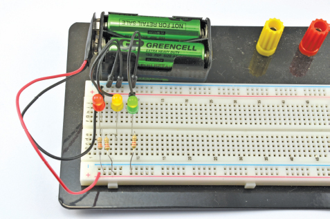
FIGURE 4-1 LEDs on a breadboard
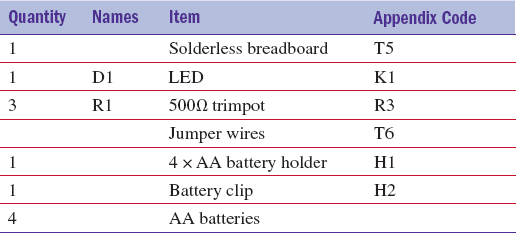
You Will Need
Diodes
We need to understand LEDs a little better if we are to successfully use them. LED stands for light-emitting diode, so let’s start by looking at what a diode is (Figure 4-2).
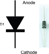
FIGURE 4-2 A diode
A diode is a component that only lets current flow in one direction. It has two leads, one called the anode, and the other called the cathode. If the anode is at a higher voltage than the cathode (it has to be greater by about half a volt), then it will conduct electricity and is said to be “forward-biased.” If on the other hand the anode isn’t at least half a volt higher than the cathode, it is said to be “reverse-biased” and no current flows.
LEDs
An LED is just like a regular diode except that when it is forward-biased, it conducts and generates light. It also differs from a regular diode in that the anode usually needs to be at least 2V higher than the cathode for it to be forward-biased.
Figure 4-3 shows the schematic diagram for driving an LED.
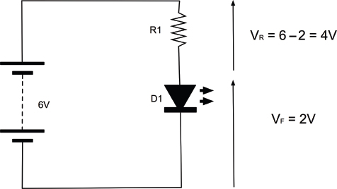
FIGURE 4-3 Limiting current to an LED
The key to this circuit is to use a resistor to limit the current flowing through the LED. A normal red LED will typically just be lit at about 5mA and is designed to be used at around 10 to 20mA (this is called the “forward current” or IF). We will aim for 15mA for our LED. We can also assume that when it is conducting, there will be about 2V across it. This is called the “forward voltage” or VF. That means there will be 6 – 2 = 4V across the resistor.
So, we have a resistor that has a current flowing through it (and the LED) of 15mA and a voltage across it of 4V. We can use Ohm’s law to calculate the value of resistance we need to achieve this:
R = V / I = 4V / 0.015A = 267Ω
Resistors come in standard values, and the nearest higher value in our resistor starter kit is 330Ω.
As I mentioned earlier, a red LED will almost always light quite brightly with something like 10–20mA. The exact current is not critical. It needs to be high enough to make the LED light, but not exceed the maximum forward current of the LED (for a small red LED, typically 25mA).
Table 4-1 shows a section of the datasheet for a typical range of LEDs of different colors. Note how VF changes for different color LEDs. This will mean you may need to use a different resistor, but usually if the supply voltage is above say 6V, then small variations in VF for color will not require a different resistor value.
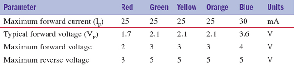
TABLE 4-1 An LED Datasheet
The other parameter you should be aware of is the “maximum reverse voltage.” If you exceed this by, say, wiring your LED the wrong way around, it is likely to break the LED.
Many online series resistor calculators are available that— given the supply voltage VF and current IF for your LED—will calculate the series resistor for you. For example:
Table 4-2 is a useful rough guide, assuming a forward current of around 15mA.
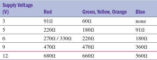
TABLE 4-2 Series Resistors for LEDs
Trying It Out
You might like to try out your LEDs and get them lit up on the breadboard. So, using Figures 4-4 and 4-5 as a guide, wire up your breadboard. Remember that the longer lead of the LED is normally the anode (positive) and thus should be to the left of the breadboard.
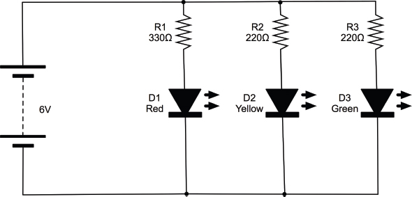
FIGURE 4-4 An LED’s schematic
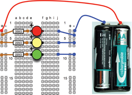
FIGURE 4-5 An LED breadboard layout
An important point to notice here is that each LED has its own series resistor. It is tempting to use one lower value current limiting resistor and put the LEDs in parallel, but don’t do this. If you do, the LED with the lowest VF will hog all the current and probably burn out, at which point the LED with the next lowest VF will do the same, until all the LEDs are dead.
How to Select the Right LED for the Job
LEDs come in all colors, shapes, and sizes. Many times, you just want a little indicator light, in which case a standard red LED is usually fine. However, there are many other options, including LEDs bright enough to be used as lamps.
You Will Need
Brightness and Angle
When selecting an LED, they may simply be described as “standard” or “high brightness” or “ultra-bright.” These terms are subjective and open to abuse by unscrupulous vendors. What you really want to know is the LED’s luminous intensity, which is how much light the LED produces. You also want to know the angle over which the LED spreads the light.
So, for a flashlight, you would use LEDs with a high luminous intensity and a narrow angle. Whereas for an indicator light to show that your gadget is turned on, you would probably use an LED with a lower luminous intensity but a wider angle.
Luminous intensity is measured in millicandela or mcd, and a standard indicator type LED will typically be around 10 to 100 mcd, with a fairly wide viewing angle being 50 degrees. A “high brightness” LED might be up to 2000 or 3000 mcd, and an ultra-bright anything up to 20,000 mcd. A narrow beam LED is about 20 degrees.
Multicolor
We have already explored the more common LED colors, but you can also get LED packages that actually contain two or three LEDs of different colors in the same package. Common varieties are red/green as well as full-color RGB (Red Green Blue). By varying the proportion of each color, you can change the color of the light produced by the LED package.
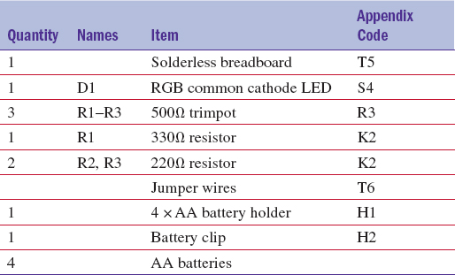
Figure 4-6 shows the schematic we can use to try out a little experiment with an RGB LED.
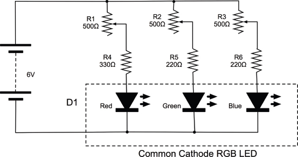
FIGURE 4-6 An RGB LED test schematic
We are going to use a variable resistor with each of the red, green, and blue LEDs. The fixed resistors (R4, R5, and R6) are to prevent too much current flowing when the slider of the variable resistor is right at 6V.
Figure 4-7 shows the breadboard layout for this. The common lead of the LED is the longest lead, while the other three are the three-color anodes.
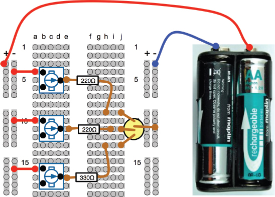
FIGURE 4-7 An RGB LED test breadboard layout
Once all the components are in the board and you have attached the battery, you should be able to mix various colors by changing the position of the three sliders. Figure 4-8 shows the circuit in operation.
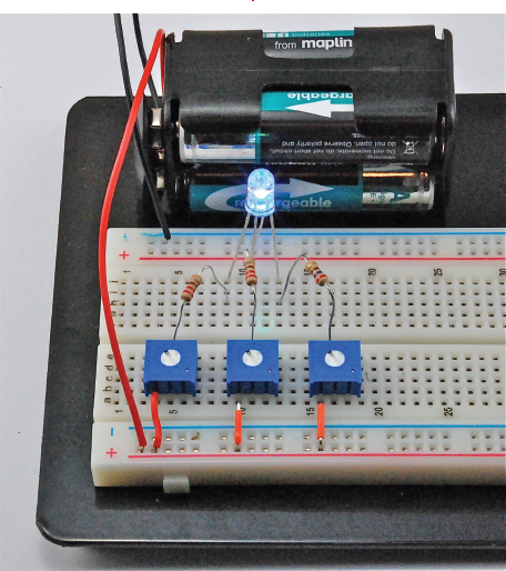
FIGURE 4-8 An RGB test
IR and UV
As well as visible LEDs, you can also buy LEDs whose light is invisible. This is not as pointless as you might think. Infrared LEDs are used in TV remote controls, and ultraviolet LEDs are used in specialist applications such as checking the authenticity of bank notes and making people’s white clothes light up in clubs.
Use these LEDs just like any other LED. They will have a recommended forward current and voltage and will need a series resistor. Of course, checking that they are working is trickier. Digital cameras are often a little sensitive to infrared and you may see a red glow on the screen.
LEDs for Illumination
LEDs are also finding their way into general household lighting. This has come about because of improvements in LED technology that have produced LEDs with a brightness comparable to incandescent light bulbs—well, they are getting there anyway. Figure 4-9 shows one such high-brightness LED. In this case, it’s a 1-W LED, although 3-W and 5-W LED modules are also available.
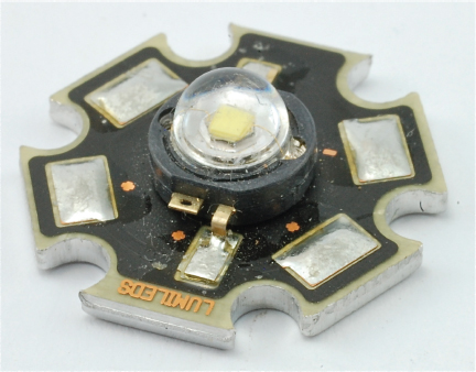
FIGURE 4-9 A high-power LED
The cool-looking star shape is thanks to the aluminum heat sink that the LED is attached to. At full power, these LEDs produce enough heat to warrant such a heat sink to disperse the heat into the air.
These LEDs can use a resistor to limit the current, but a quick calculation will show you that you will need quite a high-power resistor. A better approach to using these LEDs is to use a constant current driver, which is the subject of the next section.
How to Use a LM317 to Make a Constant Current Driver
Using a resistor to limit the current is all right for small LEDs. However, it is a bit hit or miss since it is very dependent on the LED being used and the power being provided. So for low-power LEDs, where the supply current is not critical it works okay. For high-power LEDs, you can use a series resistor (it will need to be quite high power), but a better way is to use a constant current driver.
As the name suggests, the constant current driver will supply the same current whatever voltage it is supplied with and whatever the forward voltage of the LED. You just set the current and that is how much current will flow through the high-power LED.
A very useful IC that is often used for this purpose is the LM317. This IC is primarily intended as an adjustable voltage regulator, but can easily be adapted for use in regulating current.
This project will start off on breadboard and then we will cut the top off a battery clip and solder the LM317 and resistor to it to make an emergency 1-W LED light.
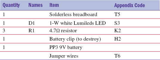
You Will Need
Design
Figure 4-10 shows the schematic diagram for regulating the current to a high-power LED like the one shown in Figure 4-9.
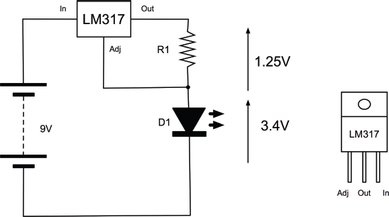
FIGURE 4-10 An LM317 constant current LED driver schematic
The LM317 is very easy to use in a constant current mode. It will always strive to keep its output voltage at exactly 1.25V above whatever voltage the Adj (adjust) pin is at.
The LED we are going to use is a 1W white light LED. It has an If (forward current) of 300mA and a Vf (forward voltage) of 3.4V.
The formula for calculating the right value for R1 for use with the LM317 is:
R = 1.25V / I
so in this case, R = 1.25 / 0.3 = 4.2Ω
If we used a standard resistor value of 4.7Ω, then this would reduce the current to:
I = 1.25V / 4.7Ω = 266 mA
Checking the power rating for the resistor, the LM317 will always have 1.25V between Out and Adj. So:
P = V × I = 1.25V × 266mA = 0.33W
A half-watt resistor will therefore be fine.
The LM317 also needs its input to be about 3V higher than its output to guarantee 1.25V between Adj and the output. This means that a 6V battery would not be quite high enough because the forward voltage is 3.4V. However, we could drive the circuit using a 9V battery or even a 12V power supply without modification, since whatever the input voltage, the current will always be limited to about 260mA.
A quick calculation of the power consumed by the LM317 will reassure us that we are not going to come near exceeding its maximum power rating.
For a 9V battery, the voltage between In and Out will be 9 – (1.25 + 3.4) = 4.35V. The current is 260mA, so the power is: 4.35 × 0.26 = 1.13W.
According to its data sheet, the maximum power handling capability of the LM317 is 20W, and it can cope with a current of up to 2.2A for a supply voltage of less than 15V. So we are fine.
Breadboard
Figure 4-11 shows the breadboard layout for this, and Figure 4-12 displays the actual breadboard. These LEDs are almost painfully bright, so avoid staring at them. When working with them, I cover them with a sheet of paper so I can see when they are on without being temporarily blinded!
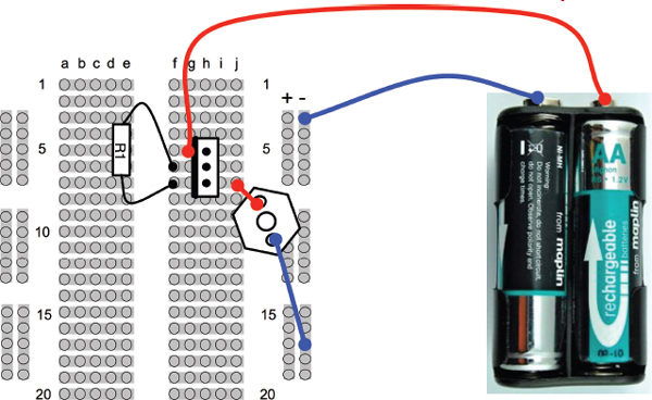
FIGURE 4-11 The LED constant current driver breadboard layout
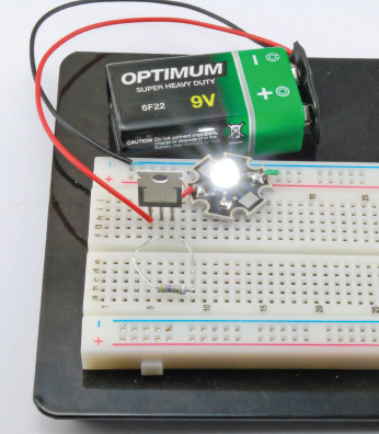
FIGURE 4-12 The LED constant current driver
You will need to solder lengths of solid-core wire to the LED’s terminals so it can plug into the breadboard. It is a good idea to leave the insulation on so there is no chance of the bare wires touching the heat sink and shorting.
Construction
We will use this to make a little emergency lantern by hacking a battery clip to build the electronics on top of it so it can be clipped on top of a PP3 battery in the event of a power failure (Figure 4-13).
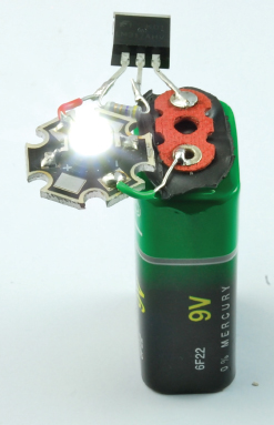
FIGURE 4-13 Emergency LED lighting
Figures 4-14a thru 4-14d shows the stages involved in soldering this up.
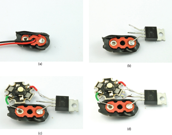
FIGURE 4-14 Making an emergency 1-W LED light
First, remove the plastic from the back of the battery clip using a craft knife. Then, unsolder the exposed leads (Figure 4-14a).
The next step (Figure 4-14b) is to solder the Input lead of the LM317 to the positive terminal of the battery clip. Remember that the positive connector on the clip will be the opposite of the connector on the battery itself, so the positive connector on the clip is the socket-shaped connector. Gently bend the leads of the LM317 apart a little to make this easier.
Now solder the LED in place making sure the cathode of the LED goes to the negative connection on the battery clip (Figure 4-14c).
Finally, solder the resistor across the two topmost leads of the LM317 (Figure 4-14d).
How to Measure the Forward Voltage of an LED
If you want to power lots of LEDs at the same time, it is a good idea to test a few of the LEDs you actually intend to use and measure the forward voltage at the current you intend to use. Figure 4-15 shows how you would do this.
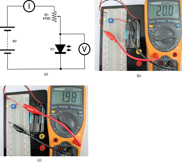
FIGURE 4-15 Measuring the forward voltage of an LED
Figure 4-15a shows the schematic diagram. A variable resistor is used to vary the current through the LED and when the desired forward current is set, the voltage can be read.
The current and voltage do not have to be read at the same time, but if you do have two meters, this does make life easier.
Set the variable resistor to its middle point and wire up the breadboard as shown in Figure 4-15b. You will probably have to move the positive lead of your multimeter to a different socket when measuring current. Select a current range of 200mA DC. Now adjust the variable resistor until the current reads 20mA.
We can now measure the voltage across the LED. To do this, first disconnect the multimeter, put the positive multimeter back in the right socket for measuring voltage, and then change the range to 20V DC. Wire it up as shown in Figure 4-15c and measure the voltage. In this case, it was 1.98V.
You Will Need
How to Power Large Numbers of LEDs
If you use something like a 12V power supply, you can put a number of LEDs in series, with just one LED. In fact, if you know the forward voltages fairly accurately, and the power supply is well regulated, you can get away without any series resistor at all.
So, if you have fairly standard LEDs that have a forward voltage of 2V, then you could just put six of them in series. However, it will not be terribly easy to predict how much current the LEDs will take.
A safer approach is to arrange the LEDs in parallel strings, each string having its own current-limiting resistor (Figure 4-16).
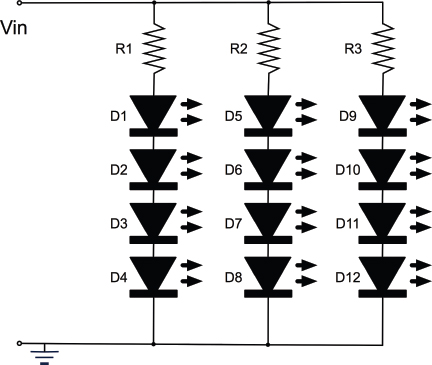
FIGURE 4-16 Powering multiple LEDs
Although the math for this isn’t too hard, there can be a fair bit of it, so you can save yourself a lot of time by using an online calculator like http://led.linear1.org/led.wiz (Figure 4-17).
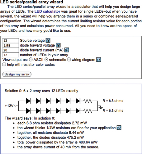
FIGURE 4-17 The LED wizard
In this particular designer, you enter the source voltage for the overall supply, the LED forward voltage, the desired current for each LED, and the number of LEDs you want to light. The wizard then does the math and works out a few different layouts.
One consideration is that where you have a string of LEDs in series, if any of the LEDs fail, then all the LEDs will be off.
How to Make LEDs Flash
The 555 timer IC is a useful little IC that can be used for many different purposes, but is particularly convenient for making LEDs flash or generating higher frequency oscillations suitable for making audible tones (see Chapter 9).
We are going to make this design on breadboard and then transfer it to a more permanent home on a bit of stripboard.
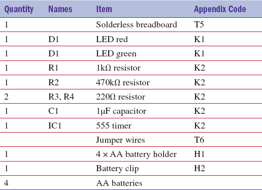
You Will Need
Breadboard
The schematic for the LED flasher is shown in Figure 4-18.
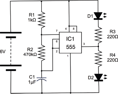
FIGURE 4-18 The LED flasher schematic
The breadboard layout is shown in Figure 4-19. Make sure you have the IC the right way up. There will be a notch in the IC body next to the top (pins 1 and 8). The capacitor and LEDs must both be the correct way around, too.
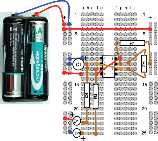
FIGURE 4-19 The LED flasher breadboard layout
Figure 4-20 shows the finished breadboard. You should find that the LEDs alternate, each staying on for about a second.
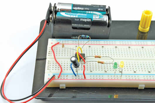
FIGURE 4-20 The LED flasher on breadboard
Now that we know that the design is right and everything works, try swapping out R2 with a 100kΩ resistor and notice the effect on the flashing.
The 555 timer is a very versatile device, and in this configuration it oscillates at a frequency determined by the formula:
frequency = 1.44 / ([R1 + 2 * R2] * C)
where the units of R1, R2, and C1 are in Ω and F. Plugging in the values for this design, we get:
frequency = 1.44 / ([1000 + 2 * 470000] * 0.000001) = 1.53 Hz
One hertz (or Hz) means one oscillation per second. When we use the 555 timer in a later chapter to generate an audible tone, we will be using the same circuit to generate a frequency in the hundreds of hertz.
As with so many electronic calculations, there are also online calculators for the 555 timer.
How to Use Stripboard (LED Flasher)
Breadboard is very useful for trying things out, but not so useful as a permanent home for your electronics. The problem is that the wires tend to fall out, and it’s all a bit big and bulky.
Stripboard (Figure 4-21) is a bit like general-purpose printed circuit board. It is a perforated board with conductive strips running underneath, rather like breadboard. The board can be cut to the size you need and components and wires soldered onto it.
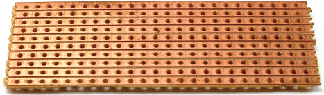
FIGURE 4-21 Stripboard
Designing the Stripboard Layout
Figure 4-22 shows the final stripboard layout for the LED flasher that we made in the previous section. It is not easy to explain how we got to this from the schematic and breadboard layout. There is a certain amount of trial and error, but there are a few principals you can follow to try and make it easier.
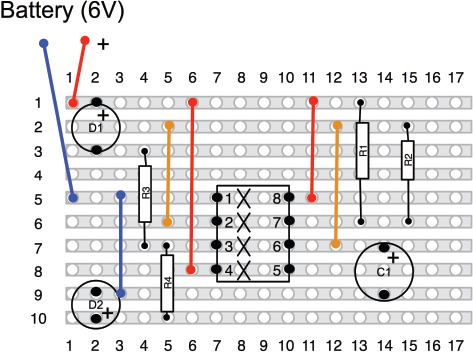
FIGURE 3-22 An LED flasher stripboard layout
The first is to use a drawing tool with a stripboard template. For Mac users, with OmniGraffle, a template is available for download from the book’s web site (www.hackingelectronics.com). There is also an image file that can be printed out and used as a template to sketch out the design.
The Xs underneath the IC are breaks in the track, which we will make with a drill bit. One of the goals of a good stripboard layout is to try and avoid making too many breaks in the track. Breaks are unavoidable for an IC like this. If we did not make them, pin 1 would be connected to pin 8, pin 2 to pin 7, and so on, and nothing would work.
The colored lines on the board are linking wires. So, for instance, from the schematic diagram of Figure 4-18, we can see that pins 4 and 8 of the IC should be connected together and both go to the positive supply. This is accomplished by the two red linking wires. Similarly, pins 2 and 6 need to be connected together. This is accomplished by using the orange leads.
Although logically the stripboard layout is the same as the schematic, the components are in rather different places. The LEDs are on the left in the stripboard layout and on the right on the schematic. It is not always like this, and it’s easier if they are similar, but in this case the left-hand pins of the IC include the output pin 3 that the LEDs need, and the pins connected to R1, R3, and C1 are all on the right-hand side of the IC.
Try making a stripboard layout from the schematic, you may well come up with a different and better layout than the one I produced.
The steps I went through in designing this layout are as follows:
1. Place the IC fairly centrally, with a bit more room above than below and with pin 1 uppermost (convention).
2. Find a good place for R3 and R4 to be put so the strips are at least three holes apart for one resistor lead, when the other lead of each resistor goes to pin 3.
3. Pick the top track of the stripboard to be +V so it can be close to the positive end of one of the LEDs
4. Pick row 5 to be the ground connection. This way it can run straight on to pin 1 of the IC.
5. Add a link wire from row 5 to row 9 to provide the negative connection for the LED D2.
6. Put a jumper wire from pin 4 of the IC to row 1 (+V).
Turning now to the right-hand side of the board:
1. Put a jumper in connecting pin 8 of the IC to row 1 (+V).
2. R1 and R2 both have one end connected to pin 7, so put them side by side with the far end of R1 going to row 1 (+V).
3. R2 needs to connect to pin 6, but pin 6 and pin 7 of the IC are too close together for the resistor to lie flat, so take that lead up to the unused row 2 instead, then put jumpers from row 2 down to both pin 6 and pin 2 of the IC.
4. Finally, C1 needs to go between pin 6 (or pin 2, but 6 is easier) and GND (row 9).
A good way of checking that you have made all the connections you need is to print off the schematic and then go through each connection on the stripboard and check off its counterpart on the schematic.
This may all seem a little like magic, but try it. It’s not as hard to do as it is to describe.
You Will Need
You will need all the components listed in the section “How to Make LEDs Flash,” plus the following items.
Before we start soldering, it is worth considering what kind of LEDs you want to use for this project. You may decide to use higher-brightness LEDs or power the project from a lower voltage. If you do decide on this, recalculate the values for R3 and R4 and try it out on the breadboard layout. The 555 timer IC needs a supply voltage between 4.5V and 16V, and the output can supply up to 200mA.
Construction
Step 1. Cut the Stripboard to Size
There is no point in having a large bit of stripboard with just a few components on it, so the first thing we need to do is cut the stripboard to the right size. In this case, it’s ten strips each of 17 holes. Stripboard doesn’t actually cut very well. You can use a rotary tool, but wear a mask because the dust from the stripboard is nasty and you really do not want it in your lungs. I find the easiest way to cut stripboard is actually to score it with a craft knife and metal ruler on both sides and then break it over the edge of your work surface.
Score it across the holes, not between them. When the board is cut, the copper underside will look like Figure 4-23.
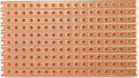
FIGURE 4-23 A stripboard cut to size
Step 2. Make the Breaks in the Tracks
A good tip is to use a permanent marker and put a dot in the top left corner. Otherwise, it is very easy to get the board turned around, resulting in breaks and links being put in the wrong place.
To make the breaks, count the position in rows and columns of the break from the top of the board layout and then push a bit of wire so you can identify the right hole on the copper side of the stripboard (Figure 4-24a). Using a drill bit, just “twizzle” it between thumb and forefinger to cut through the copper track. It usually only takes a couple of twists (Figure 4-24b and c).

FIGURE 4-24 Cutting a track on stripboard
When you have cut all four breaks, the bottom side of the breadboard should look like Figure 4-25. Check very carefully that none of the burrs from the copper have lodged between the tracks and that the breaks are complete. Photographing the board and then zooming in is a great way of actually checking the board.
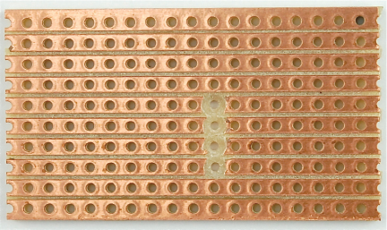
FIGURE 4-25 The stripboard with breaks cut
Step 3. Make the Wire Links
A golden rule of any type of circuit board construction, including when using stripboard, is to start with the lowest-lying components. This is so that when you turn the board on its back to solder it, the thing being soldered will stay in place through the weight of the board.
In this case, the first thing to solder is the links.
Strip and cut solid-core wire to slightly longer than the length of the link. Bend it into a U-shape and push it through the holes at the top, counting the rows and columns to get the right holes (Figure 4-26a). Some people get very skilled at bending the wires with pliers to just the right length. I find it easier to bend the wires with a bit of a curve so they will kind of squash into the right holes. I find this easier than trying to get the length just right from the start.
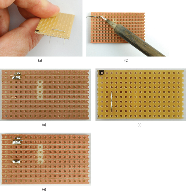
FIGURE 4-26 Soldering the links
Turn the board over (see how the wire is held in place) and solder the wire by holding the iron to the point where the wire emerges from the hole. Heat it for a second or two and then apply the solder until it slows along the track, covering the hole and wire (Figure 4-26b and c).
Repeat this process for the other end of the lead and then snip off the excess wire (Figure 4-26d and e).
When you have soldered all the links, your board should look like the one in Figure 4-27.
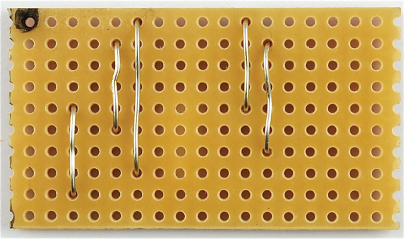
FIGURE 4-27 The stripboard with all its links
Step 4. Resistors
The resistors are the next lowest components to the board, so solder these next, in the same way as you did the links. When they are all soldered, the stripboard should look like Figure 4-28.
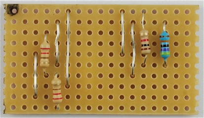
FIGURE 4-28 The stripboard with resistors in place
Step 5. Solder the Remaining Components
Next, solder the LED, capacitor (which can be laid on its side as shown in Figure 4-29), and finally the LEDs and connectors to the battery clip.
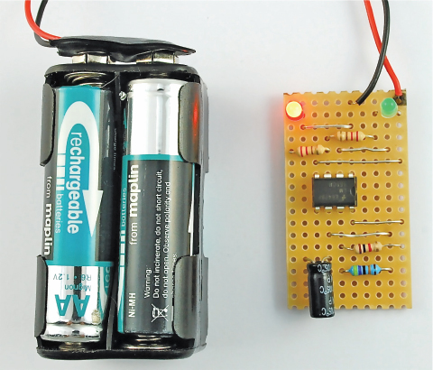
FIGURE 4-29 The LED flasher on the stripboard
That’s it. Now it’s time for the moment of truth. Before you plug it in, do a very careful inspection for any shorts on the underside of the board.
If everything seems in order, connect the battery clip to the battery.
Troubleshooting
If it does not work, immediately unplug it and go back though and check everything, especially that the LEDs, IC, and capacitor are the correct way around. Also check that the batteries are okay.
How to Use a Laser Diode Module
Lasers are best bought as laser modules. The difference between a laser module and a laser diode is that the module includes a laser diode as well as a lens to focus the beam of laser light and a drive circuit to control the current to the laser diode.
If you buy a laser diode, you will have to do all this yourself.
A laser diode module, such as the 1-mW module shown in Figure 4-30, comes with a datasheet that says it needs to be supplied with 3V. So, all you need to do is find it a 3V battery and connect it up.
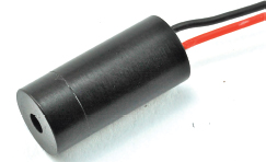
FIGURE 4-30 A laser diode module
Hacking a Slot Car Racer
Slot cars are a lot of fun, but could be improved by adding headlights and working brake lights to the car (Figure 4-31).
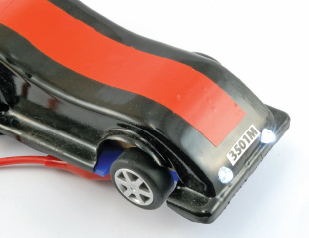
FIGURE 4-31 A modified slot car racer
LEDs are just the right size to be fitted front and back into a slot car.
You Will Need
You will need the following items to add lights to your slot car.
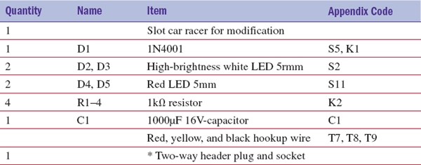
* I used a scavenged two-way header socket and plug to make it easier to work on the two halves of the car. This is not essential.
The slot car used here was part of a build-your-own slot car that has plenty of room inside for the electronics. Plan ahead and make sure you can fit everything in.
Storing Charge in a Capacitor
To make the brake lights stay on for a few moments after the car has stopped, you will need a capacitor to store charge.
If you think back to the idea of electricity as water flowing in a river, then a capacitor is a bit like a storage tank. Figure 4-32 shows how a capacitor can be used to store charge.
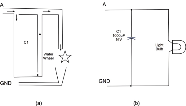
FIGURE 4-32 A capacitor as a tank
Figure 4-32a shows a tank (c1) being filled with water through A. Throughout this, water will also flow along the top and drive a water wheel, turning electrical energy into motion, a bit like how a light bulb or LED turns electrical energy into light. The water falls out of the bottom, returning to ground. Imagine a pump (like a battery) pulling the water back up for another circuit. If the water stops flowing into C1 through A, then C1 will still be full of water that will keep the water wheel turning until the water level in C1 drops below that of the outlet of the water well.
Figure 4-32b shows the electronic equivalent of this circuit. While the voltage at A is higher than GND, C1 will fill with charge and the light will be lit.
When the voltage at A is disconnected, the capacitor will discharge through the light bulb, lighting it. As the level of voltage drops in the capacitor, the bulb will gradually dim until it goes out as it reaches GND.
On the face of it, you can think of capacitors as being a bit like batteries. Both store charge. However, there are some very important differences.
• Capacitors only store a tiny fraction of the charge that a battery of the same size can store.
• Batteries use a chemical reaction to store electrical energy. This means their voltage remains relatively constant until they are spent, at which time it falls off rapidly. Capacitors, however, drop evenly in voltage as they discharge, just like the level of water decreasing in a tank.
Design
Figure 4-33 shows the schematic diagram for this modification.
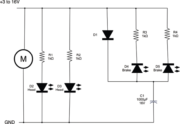
FIGURE 4-33 A schematic diagram for the slot car modification
The headlights (D2 and D3) are powered all the time from the slot car’s connection to the track, so whenever the motor is running the LEDs will light.
The brake lights are more interesting. These will automatically come on when the car stops, and then go off after a few seconds. To do this, we make use of a capacitor C1.
When the car is powered, C1 will be charged through D1. At this point, the brake lights D4 and D5 will not be lit because they will be reverse-biased—that is, the voltage going in from the car tracks will be higher than the voltage at the top of the capacitor.
When you release the trigger on the controller, there will be no voltage coming in. Now the voltage at the top of the capacitor will be higher than the voltage coming in, so the capacitor will discharge through D4 and D5, making them light.
Construction
Figure 4-34 shows how the components are laid out in the two halves of the car.
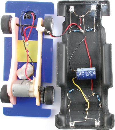
FIGURE 4-34 The components inside the car
How you lay these out in your vehicle may vary depending on how much space you have.
Holes were drilled in the case to take the 5mm LEDs. The LEDs are a snug fit in the holes and stay in place without any glue.
Figure 4-35 shows a wiring diagram for the arrangement that makes it easier to see what is going on.
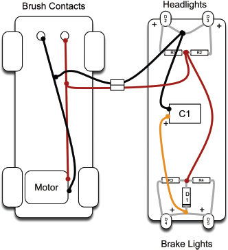
FIGURE 4-35 The wiring diagram for the modified car
Use your multimeter of the 20V range to identify which is the positive power connector on the contacts at the front of the car. This contact is connected to the red lead.
The longer leads of the LEDs are the positive connections, and the capacitor’s negative lead should be marked with a “-”.
The optional connector makes it easier to work on the two halves of the car separately.
Testing
Testing really just involves trying out the car on the track. If the headlight LEDs are not on as soon as you squeeze the trigger on the controller, check the wiring, paying special attention to the polarity of the LEDs.
Summary
We have learned how to use LEDs in this chapter, as well as picked up some good building skills so we can make our creations a bit more permanent using stripboard.
In the next chapter, we will examine sources of power, including batteries, power supplies, and solar panels. We will also look at how to select the right kind of battery, repurpose old rechargeable batteries, and use them in our projects.
..................Content has been hidden....................
You can't read the all page of ebook, please click here login for view all page.