
7
Hacking with Modules
There are many modules available that provide a great shortcut when hacking together a project. These modules are usually a tiny PCB with a few components on them and some convenient connection points. They make it very easy to use some surface-mounted ICs that would otherwise be very difficult to solder connections to. Many of these modules are designed to be used with microcontrollers like the Arduino.
In this chapter, you will explore some of the more fun and useful modules available from suppliers like SparkFun and Adafruit, most of whose modules are also open-source hardware. So you’ll get to see the schematics for them and even make your own modules using the design if you wish.
Access to the schematics and data sheets is very useful when trying to use a module. There are a few important things you need to know about any module before you use it:
• What is the range of supply voltage?
• How much current does it consume?
• How much current can any outputs supply?
How to Use a PIR Motion Sensor Module
PIR motion sensors are used in intruder alarms and for automatic security alarms. They detect movement using infrared light. They are also cheap and easy to use.
In this example, you will first experiment with a PIR module using it to light an LED, and then look at how it could be hooked up to an Arduino to send a warning message to the Serial Console.
You Will Need (PIR and LED)
Breadboard
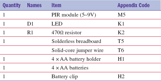
Figure 7-1 shows the schematic diagram for this experiment.
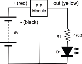
FIGURE 7-1 Schematic diagram— using a PIR module with an LED
Looking at the datasheet for this particular module, the supply voltage range is 5V to 7V, so it will work just fine with our four AA batteries.
The module is very easy to use. You just supply it with power and its output goes high (to supply voltage) when movement is detected and then back low again after a second or two.
The datasheet also says that the output can supply up to 10mA. That isn’t a great deal, but is enough to light an LED. By choosing a 470Ω resistor, we will be limiting the current to:
I = V / R = (6V – 2V) / 470Ω = 4 / 470 = 8.5mA
Figure 7-2 shows the breadboard layout, while Figure 7-3 offers a photograph of the actual breadboard.
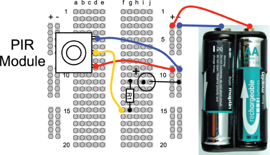
FIGURE 7-2 Breadboard layout— using a PIR module with an LED
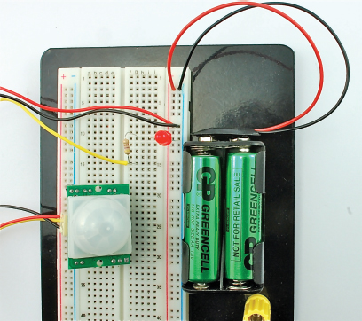
FIGURE 7-3 Using a PIR module with an LED
The PIR module has three pins labeled +5V, GND, and OUT. The supplied connector lead has red, black, and yellow leads. Hook it up so the red lead connects to the connection labeled +5V.
When it’s powered up, the LED will light every time movement is detected.
Having already discussed the PIR sensor so we know what to expect of it, it’s time to interface it with an Arduino.
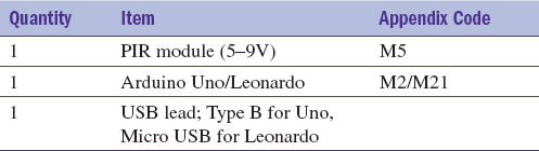
You Will Need (PIR and Arduino)
To interface the PIR sensor with an Arduino, you really only need the PIR sensor and an Arduino.
Construction
Figure 7-4 shows the schematic diagram for this, while Figure 7-5 shows how the PIR module is wired to the module. To get the wires to stay in the Arduino sockets, it helps to put a little zigzag bend in the tinned end of the wire lead.
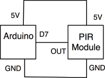
FIGURE 7-4 Schematic diagram for the Arduino and PIR sensor
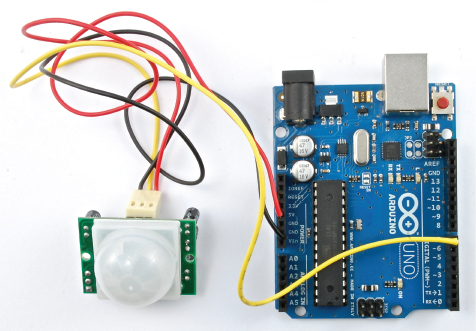
FIGURE 7-5 The Arduino and the PIR sensor
Before you move onto the next stage of programming the Arduino, temporarily remove the OUT lead from its Arduino socket. The reason for this is that you do not know what sketch was last running on the Arduino. It might have been something where pin 7 was an output, and if it was, this could easily damage the output electronics of the PIR sensor.
Software
Load the sketch “pir_warning” into the Arduino IDE and onto the Arduino board, and then plug the yellow “OUT” lead back into pin 7 on the Arduino.
When you launch the Serial Monitor (Figure 7-6), you will see an event appear every time movement is detected. Imagine leaving this running while away from your computer—to detect snoopers!
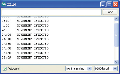
FIGURE 7-6 The Serial Monitor showing intruder alerts
The sketch is very straightforward.
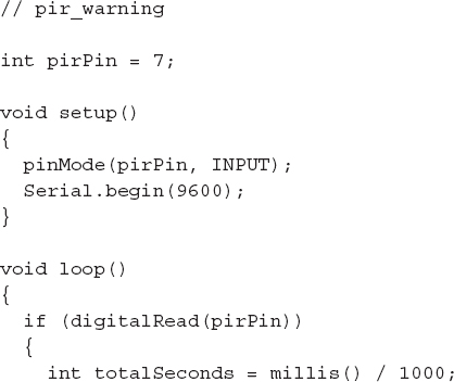

The only part of the code that is a bit different than the other sketches we have seen deals with displaying an elapsed time in minutes and seconds next to each event.
This code uses the Arduino “millis” function, which returns the number of milliseconds since the Arduino was last reset. This is then separated into its minute and second components and the various parts printed out as a message. The last part to be displayed uses the “println” command that adds a line feed to the end of the text so the next text starts on a new line.
The special character “ ” in this “println” is a tab character, to line the output up neatly.
How to Use Ultrasonic Rangefinder Modules
Ultrasonic rangefinders use ultrasound (higher frequency than the human ear can hear) to measure the distance to a sound-reflective object. They measure the time it takes for a pulse of sound to travel to the object and back. Figure 7-7 shows two different types of sonar. On the left is a low-cost sonar module (less than USD 5) with separate ultrasonic transducers for sending the pulse and receiving the echo, and a much more expensive (around USD 25) but highly specified module made by MaxBotix Inc.
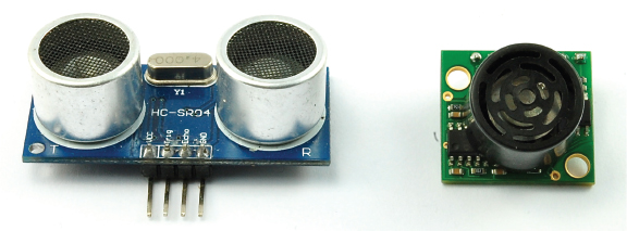
FIGURE 7-7 Ultrasonic rangefinders
To see how to use these modules with an Arduino, we will try out each in turn.
Ultrasonic range finding works the same as sonar used by ships and submarines. A sound wave is sent out from a sender, hits an object, and bounces back. Since we know the speed of sound, the distance to the sound-reflecting object can be calculated from the time it takes for the sound to come back to the receiver (Figure 7-8).
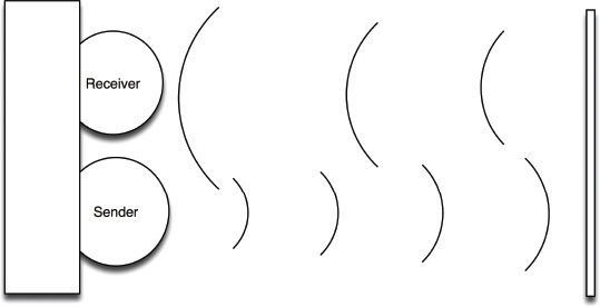
FIGURE 7-8 Ultrasonic range finding
The sound used is at a high frequency—hence, it is called ultrasonic. Most units operate at a frequency of about 40 kHz. Not many people can hear sounds above 20 kHz.
You Will Need
To try out both rangefinders, you will need the following items.
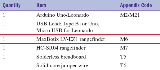
The HC-SR04 Rangefinder
These modules make the Arduino do a lot of the work, which is one reason why they are so much cheaper than the MaxBotix modules. They do, however, have the advantage that they can just fit into the side connector of an Arduino if you can spare the pins to supply them with current using two output pins (Figure 7-9).
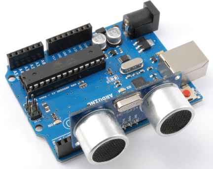
FIGURE 7-9 An HC-SR04 rangefinder on an Arduino
Load the sketch “range_finder_ budget” onto the Arduino and then plug the rangefinder module into the Arduino, as shown in Figure 7-9.
When you open the Serial Monitor, you will see a stream of distances in inches appear (Figure 7-10). Try pointing the rangefinder in different directions—say, a wall a few feet away—and confirm that the reading is reasonably accurate with a tape measure.

FIGURE 7-10 Distance readings in the Serial Monitor
The Arduino code for measuring the range is all contained within the “takeSounding_cm” function. This sends a single 10-microsecond pulse to the “trigger” pin of the ultrasonic module, which then uses the built-in Arduino function “pulseIn” to measure the time period before the echo pin goes high.
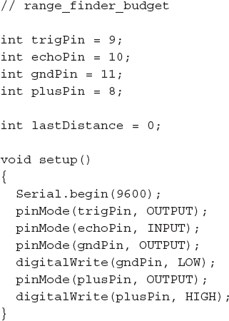
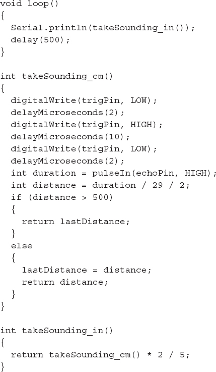
We then need to convert that time in milliseconds into a distance in centimeters. If there is no reflection because there is no object that is close enough, or the object is reflecting the sound wave away rather than letting it bounce back to the receiver, then the time of the pulse will be very large and so the distance will also be recorded as very large.
To filter out these long readings, we disregard any measurement that is greater than 5m, returning that last sensible reading we got.
The speed of sound is roughly 343 m/s in dry air at 20 degrees C, or 34,300 cm/s.
Or, put another way, 34,300 /1,000,000 cm / microsecond.
That is, 0.0343 cm/microsecond.
Put another way, 1/0.0343 microseconds/cm.
Or, 29.15 microseconds/cm.
Thus, a time of 291.5 microseconds would indicate a distance of 10 cm.
The “takeSounding_cm” function approximates 29.15 to 29 and then also divides the answer by 2, as we don’t want the distance of the whole return journey, just the distance to the subject.
In actual fact, many factors affect the speed of sound, so this approach will only ever give an approximate answer. The temperature and the humidity of the air will both affect the measurement.
The MaxBotix LV-EZ1 Rangefinder
The HC-SR04 rangefinder only has a single type of interface, and we have to tell it to generate the sonar pulse, and then time how long it takes to come back ourselves.
In contrast, the MaxBotix device does all of this for us, and what’s more it provides us with no less than three ways to get the distance readings:
• Serial data readings
• Analog (Vcc / 512) / inch
• Pulse width (147 μS/inch)
We will use the analog method to test out this device. The figure of Vcc / 512 per inch means that the analog output will be the supply voltage divided by 512 per inch. So if the object was 10 inches away, then the analog output voltage would be:
10 inches × 5V/ 512 = 0.098V
The MaxBotix module has too many pins to easily fit directly onto the Arduino connectors, so you will need to use breadboard.
Figure 7-11 shows the unit and the Arduino on the breadboard, while Figure 7-12 shows the breadboard layout.

FIGURE 7-11 The MaxBotix rangefinder and Arduino

FIGURE 7-12 The MaxBotix rangefinder and Arduino breadboard layout
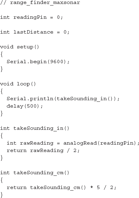
Load up the sketch “range_finder_ maxsonar” and then connect up the module as shown in Figure 7-11.
The sketch is much simpler than for the other module, and the distance in inches is just the raw analog reading (between 0 and 1023) divided by two.
Opening the Serial Monitor will produce the same stream of distance measurements as the other module.
Note that both sketches have a metric and imperial distance measurement flavor for your convenience.
How to Use a Wireless Remote Module
Radio frequency circuits usually are not worth making yourself when extremely useful modules like the one shown in Figure 7-13 are readily available for just a few dollars.
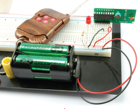
FIGURE 7-13 An RF module on breadboard
The module shown can be easily found on eBay and has a handy little key-fob sized remote with four buttons on it. These buttons can toggle four digital pins on and off on the corresponding receiver module.
It is worth noting that modules like this are also available with relays instead of digital outputs, making it very easy to hack your own remote control projects.
You will first experiment with the module on breadboard, just turning on an LED, and then in the following section, you can try connecting it to an Arduino.
You Will Need
To try out the wireless remote on breadboard, you will need the following items.

Breadboard
Figure 7-14 shows the breadboard layout used to test the remote. You could, if you wished, add three more LEDs so there was one for each channel.
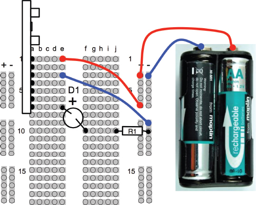
FIGURE 7-14 Breadboard layout for testing the RF module
The datasheet for this module shows that the pins are as shown in Table 7-1.
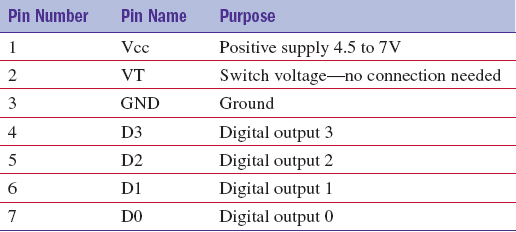
TABLE 7-1 RF Receiver Pinout
Put the module on the breadboard with pin 1 at the top of the breadboard, and wire it up as shown in Figure 7-14.
That really is all there is to it. Pressing button A should toggle the LED on and off. If you wanted to, you could add more LEDs so there was one for each channel, or try moving the LED to a different output to check that they all work.
How to Use a Wireless Remote Module with Arduino
If we are prepared to lose one of the four channels of the remote from the section “How to Use a Wireless Remote Module,” then we can plug the receiver straight into the Arduino socket A0 to A5 (see Figure 7-15).

FIGURE 7-15 Using a RF remote with an Arduino
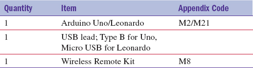
You Will Need
To try out the wireless remote with an Arduino, you will need the following items.
Before plugging the remote receiver into the Arduino, upload the sketch “rf_remote”.
Software
With the software uploaded and the RF receiver attached, when you open the Serial Monitor you should see something like Figure 7-16.
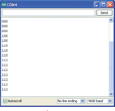
FIGURE 7-16 Remote control messages to your computer
The sketch displays as a 1 or 0 the current state of the remote control channels. So button A will not do anything (that is the button we sacrificed), but pressing the other buttons should toggle the appropriate column between 0 and 1.
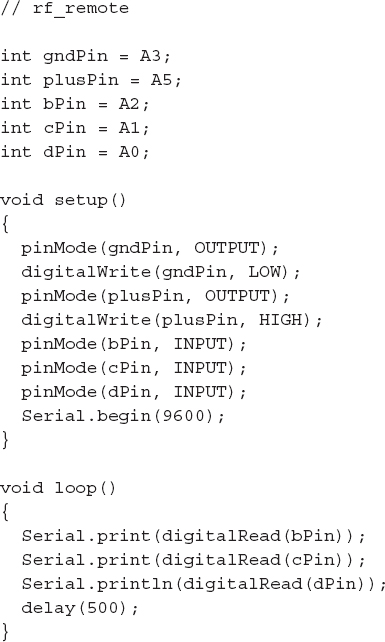
The RF receiver uses very little current, so there is no problem powering it from a digital output. In fact, doing so has the added benefit that we can actually turn it off to save power simply by setting the “plusPin” low.
How to Control Motor Speed with a Power MOSFET
This section is a little out of place because MOSFET transistors are not modules. However, this section does lead in nicely to the next section on using motor controller modules.
We first used power MOSFETs in Chapter 3. They are a kind of transistor that is particularly suited to switching high-current loads efficiently. By efficiently, I mean that they run pretty cool, working very well as electronic switches. They have a very low “on” resistance and a very high “off resistance.”
Back in Chapter 6, you used a technique called PWM (pulse-width modulation) to control the brightness of an LED by varying the length of pulses. You can use exactly the same trick on a DC motor. However, unlike an LED, motors use too much current to be driven directly from an Arduino output, so you will use a MOSFET controlled by the Arduino.
You Will Need
To build this, you will need the following items.
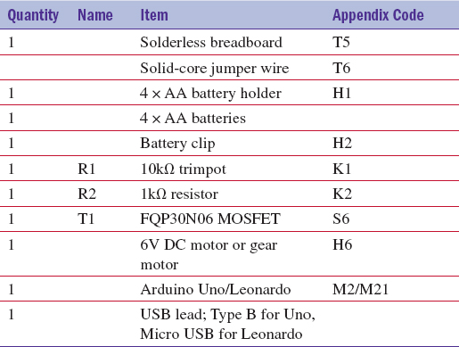
The DC motor can be any small motor you can find that is around 6V.
Breadboard
Figure 7-17 shows the schematic diagram.
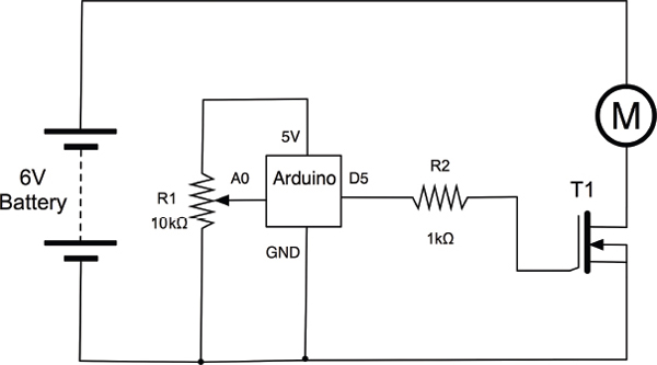
FIGURE 7-17 Schematic diagram for the MOSFET motor control
Notice that we actually have two sources of power here. We have the Arduino, which will be getting its power from your computer’s USB port and a separate battery that supplied the power to the MOSFET. This is quite a common arrangement, because the Arduino’s 5V output is not really suitable for high-current loads like a motor. Indeed, motors can create all sorts of problems for delicate electronics, so it is best not to power them from the Arduino.
There is less of a problem if the Arduino and motor share a power supply. For example, a 9V battery provides power to the Arduino through its power jack, and at the same time provides the positive supply to the motor.
I have included a resistor R2 between the Arduino output pin and the MOSFET. The circuit would work fine just connecting D5 directly to the gate; however, the gate acts like a capacitor, which means that when switched at very high speed it can actually cause quite a lot of current to flow from the digital output. This will not be a problem at the relatively slow PWM speeds used by the Arduino, but it is considered “good practice” to use a resistor here.
Figures 7-18 and 7-19 show the actual circuit and the breadboard layouts, respectively.
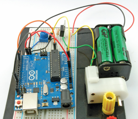
FIGURE 7-18 The MOSFET motor control
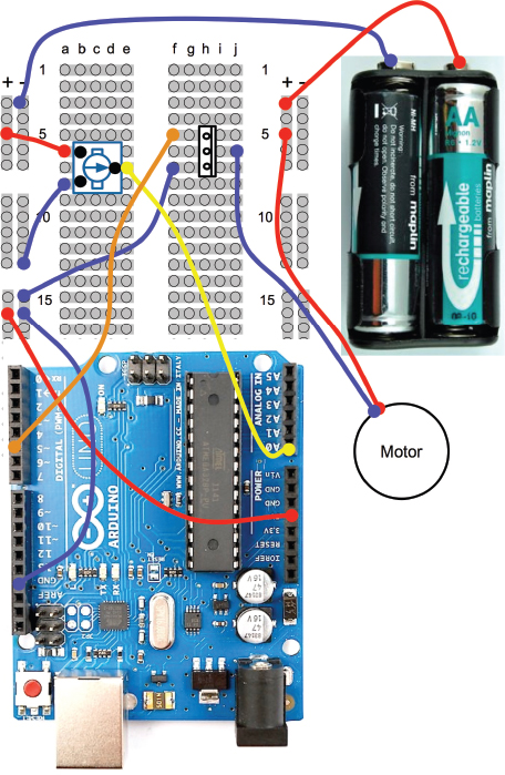
FIGURE 7-19 Breadboard layout for the MOSFET motor control
Software
Load the sketch “mosfet_motor_speed” onto the Arduino and connect the battery. You should find that by turning the variable resistor you have much finer control of the motor’s speed than you did way back in Chapter 3 when you were just controlling the gate voltage of the MOSFET.
The sketch is very similar to the sketch we used to control the brightness of an LED from an Arduino in Chapter 6.
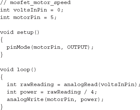
In the “loop” function, the raw reading of between 0 and 1023 from the analog input is divided by 4 to give us a number between 0 and 255 that is suitable for use with “analogWrite”.
How to Control DC Motors with an H-Bridge Module
In the earlier section of this chapter, “How to Control Motor Speed with a Power MOSFET,” we saw how you can use a MOSFET to control the speed of a motor. This is fine as long as you always want the motor to turn in the same direction. If you want to be able to reverse the direction of the motor, you need to use something called an H-Bridge.
To change the direction in which a motor turns, you have to reverse the direction in which the current flows. To do this requires four switches or transistors. Figure 7-20 shows how this works, using switches in an arrangement. You can now see why it is called an H-Bridge.

FIGURE 7-20 An H-Bridge using switches
In Figure 7-20, S1 and S4 are closed, while S2 and S3 are open. This allows current to flow through the motor with terminal “A” positive and terminal “B” negative. If we were to reverse the switches so that S2 and S3 are closed and S1 and S4 are open, then “B” will be positive and “A” will be negative, and the motor will turn in the opposite direction.
You may, however, have spotted a danger with this circuit. That is, if by some chance S1 and S2 are both closed, then the positive supply will be directly connected to the negative supply and we will have a short circuit. The same is true if S3 and S4 are both closed at the same time.
You can build an H-Bridge yourself using transistors, and Figure 7-21 shows a typical H-Bridge schematic.
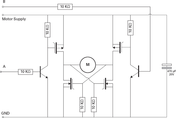
FIGURE 7-21 An example schematic for an H-Bridge
This schematic requires some six transistors and a good few other components. If you wanted to control two motors, you would need some 12 transistors, which causes everything to become quite complicated.
Fortunately, help is on hand as there are several H-Bridge ICs available that usually have two H-Bridges on a single chip and make controlling motors very easy. One such chip is available as a module from SparkFun (Figure 7-22). You will find similar modules available from other module suppliers.
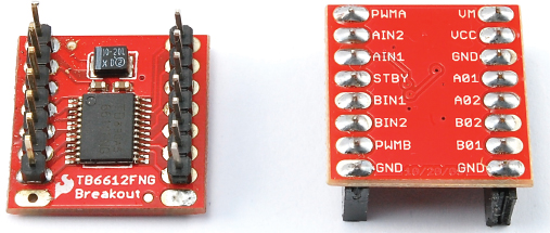
FIGURE 7-22 A SparkFun H-Bridge module
Figure 7-22 actually shows two of these modules so you can see both sides. The modules are supplied without connectors and the module on the left has pin headers soldered to it. This makes it very easy to use with breadboard.
Table 7-2 shows the pins of this module and explains the purpose of each. The module has two motor channels called A and B and can drive motors with a current of 1.2A per channel with peak currents of over twice that.
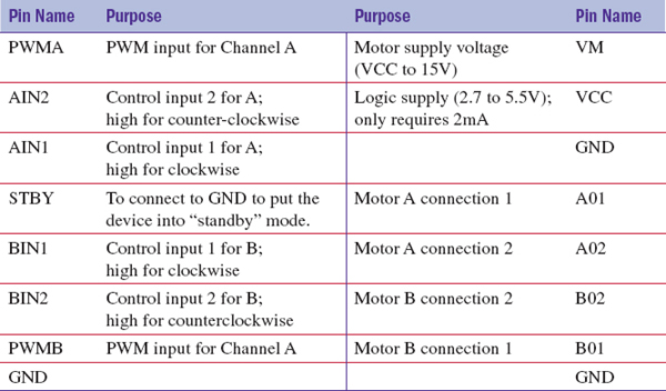
TABLE 7-2 The SparkFun TB6612FNG Breakout Board Pinout
We will experiment with this module using just one of its two H-Bridge channels (Figure 7-23).
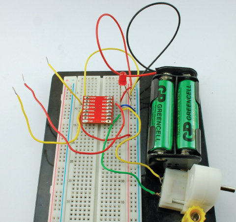
FIGURE 7-23 Experimenting with the SparkFun TB6612FNG breakout board
You Will Need
To build this, you will need the following items.
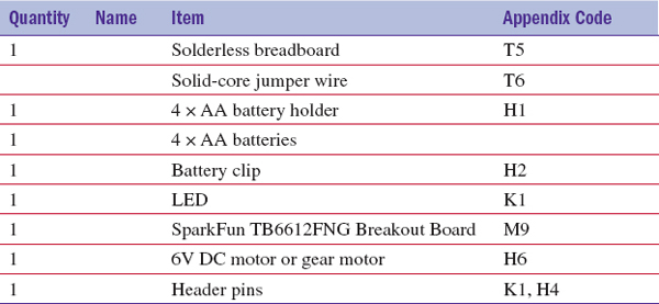
The DC motor can be any small motor around 6V.
Breadboard
Before fitting the module onto the breadboard, you need to solder the header pins into place as shown in Figure 7-22. We won’t use the bottom two GND connections, so you can just solder the top seven pins on each side.
Figure 7-24 shows the schematic diagram for the experiment, while Figure 7-25 displays the breadboard layout.
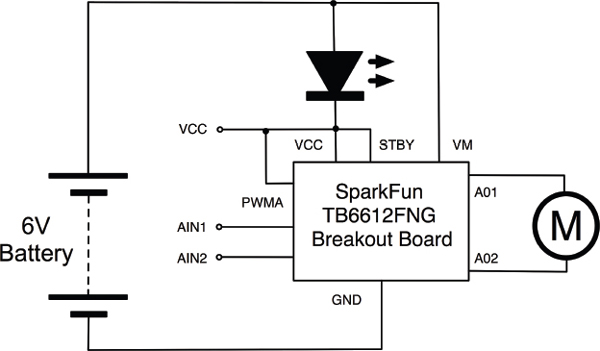
FIGURE 7-24 Schematic diagram for H-Bridge experiment
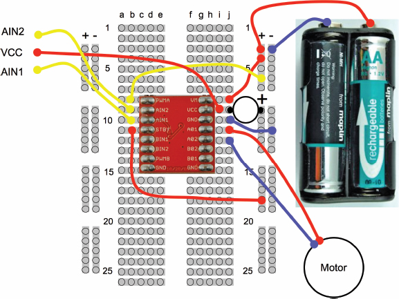
FIGURE 7-25 Breadboard layout for the H-Bridge experiment
The 6V battery pack is actually a slightly higher voltage than is (strictly speaking) allowed for VCC on the module. You would probably get away with the extra half volt above the nominal maximum voltage of 5.5V, but to play it safe, we can use an LED to drop 2V, so that VCC will be around 4V, which is well within its range.
This is a useful trick, but only use it when the current flowing is less than the maximum forward current of the LED. In fact, in this experiment, the current required for VCC is not even enough to make the LED glow.
The PWMA pin is connected to VCC, which simulates the PWN control signal being on all the time—in other words, there is full power to the motor.
Next, put everything on the breadboard as shown in Figure 7-25.
Using the Control Pins
Three of the leads from the breadboard do not actually go anywhere. You will control the motor, touching the red lead going to VCC to AIN1, and then to AIN2, in turn. Note how the motor turns first in one direction and then the other.
You might be wondering why there are two control pins, as well as the PWM pin for each motor channel. In theory, you could have one direction pin and one PWM pin, and if the PWM power was zero, then the motor would not turn at all.
The reason we have three pins to control each motor (PWM, IN1, and IN2) rather than just two is that if both IN1 and IN2 are high (connected to VCC), then the H-Bridge operates in a “braking” mode, which provides electrical braking of the motor, slowing it down. This feature is not often used, but can be useful if you want to stop the motor quickly.
How to Control a Stepper Motor with an H-Bridge Module
Normal DC motors are nice and easy to use. There are just two connections to make and if the voltage is applied one way it turns clockwise; reverse the polarity and it turns counterclockwise. The down side to normal DC motors is that if you want to know what position it has turned to, you have to use some kind of sensor.
Stepper motors are entirely different kinds of motors. They commonly have four connections. Figure 7-26 shows how a stepper motor works. Or more specifically, a bipolar stepper motor, which is the one we will try out.

FIGURE 7-26 How a bipolar stepper motor works
The motor contains a toothed rotor where each of the teeth of the rotor are magnets, of alternating north and south poles. Four coils, acting as electromagnets will, when energized in the right order, move the rotor around one step. The coils are arranged in pairs, wired so that as one pushes, its opposite number pulls.
Most stepper motors will have far more steps than the eight shown in Figure 7-26, sometimes 200 or more. This makes the motors very flexible, because they can run freely just like any other motor, by sending the stepping pulses quickly, or they can be controlled very precisely by just moving them forward one step at a time. For this reason, you will find stepper motors in inkjet printers and also 3D printers.
Because the stepper motor will only turn, if we generate a series of pulses in the right order, and need to be able to reverse the direction of current flow in the coils, we can use an Arduino to generate the control signals and an H-Bridge module to supply the power to the coils (Figure 7-27).
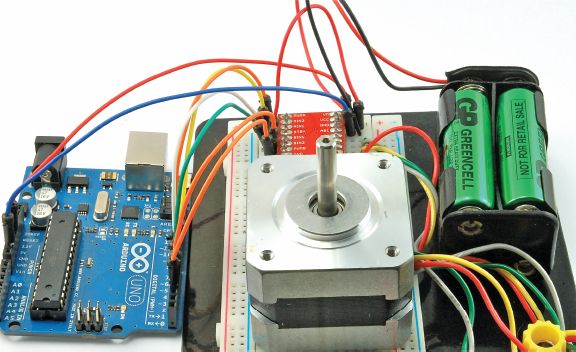
FIGURE 7-27 Controlling a stepper motor with an Arduino and an H-Bridge
Figure 7-28 shows the schematic diagram for this arrangement.

FIGURE 7-28 Schematic diagram for a stepper motor control
Identifying which lead is which on a stepper motor sometimes requires a bit of trial and error. Using a multimeter, you can measure the resistance between pairs of leads and therefore work out which leads are connected to the same coil.
Another way of finding the leads that belong to the same coil is to hold two of the leads together and see if it makes the shaft of the motor more difficult to turn. Strange, but true!
If when you turn it on, the motor doesn’t turn, you will only need to swap over one of the coil’s leads. The colors indicated in Figure 7-28 match the lead colors for the Adafruit motor.
Although the motors suggested are 12V, they will still work using the 6V supplied by the battery pack. However, do not try and power them from the 5V supply of the Arduino. They draw too much current.
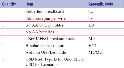
You Will Need
To build this, you will need the following items.
Construction
Figure 7-29 shows the breadboard layout.
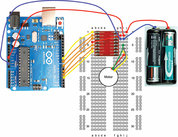
FIGURE 7-29 Breadboard layout for the stepper motor
Software
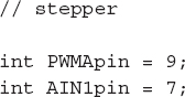
The example sketch (“stepper”) will first of all turn the motor in one direction through 200 steps and then pause for a second before turning it in the opposite direction through 200 steps. For a 200-step motor, each turn will be a full 360 degrees.
First, the pin variables are defined and the “setup” function sets them all to be outputs.
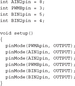
The “loop” function then directs the motor in one direction (forward) for 200 steps, pauses a second, and then directs the motor back the same number of steps, but with half the delay between steps before pausing another second. It will continue this indefinitely.
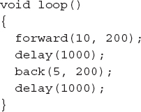
The functions “forward” and “back” both take two parameters. The first is the delay between each step in milliseconds, and the second is the number of steps to take.
The “forward” and “back” functions use the function “setStep” to set the right polarities of the two coils, in the pattern 1010, 0110, 0101, 1001.
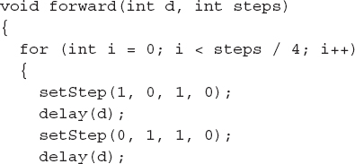
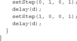
To make the motor turn in the opposite direction, the pattern is just reversed.
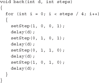
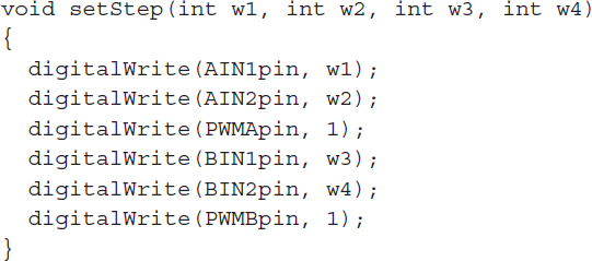
The “setStep” function actually sets the appropriate outputs of the motor controller.
How to Make a Simple Robot Rover
In this project, we will create a little roving robot. To do this, we will use the RF remote control we used in the section “How to Use a Wireless Remote Module,” with the H-Bridge module we just discussed in the section “How to Control DC Motors with an H-Bridge Module,” along with an Arduino.
The project will demonstrate how to use an Arduino to control a motor module.
The robot (Figure 7-30) will be built using a low-cost robot chassis kit that includes two gear motors.
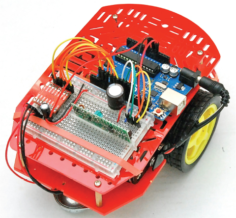
FIGURE 7-30 The robot rover
The robot is built using a small breadboard that holds both the motor module and the RF receiver module. So apart from putting pin headers on the motor controller, there is no soldering to be done in this project.
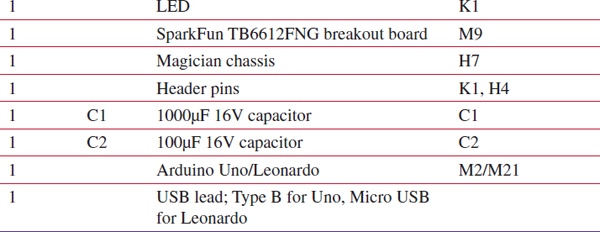
You Will Need
To build this, you will need the following items.
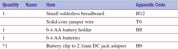
* If you use the Adafruit battery box that is already terminated in a 2.1mm plug, then you do not need this.
Construction
Figure 7-31 shows the schematic diagram for the rover.
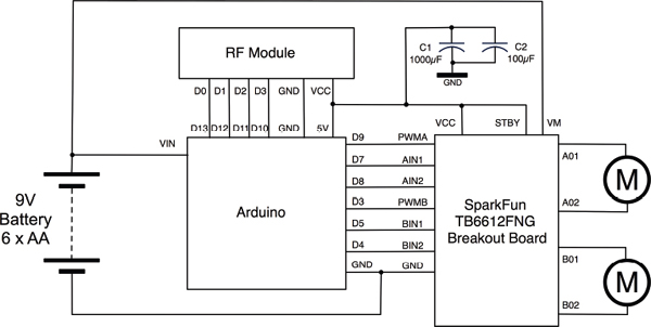
FIGURE 7-31 Schematic diagram for the rover
The use of modules simplifies this greatly. The only additional components that have been added are the two capacitors: C1 and C2. These are necessary to prevent sudden drops in battery voltage (as the motors start) from causing the Arduino to reset.
Step 1. Construct the Magician Chassis
The project is built around the Magician Chassis (Figure 7-32). This comes as a kit that is fixed together with nuts and bolts. Follow the instructions that come with the Chassis, but do not attach the battery box that comes with the kit or the support pillar that is right in the middle of the board. This is because, to power the Arduino, you need a bit more than the 5V to 6V that four AAs can supply. So, you are going to replace the battery box with one that takes six AA batteries rather than just four.
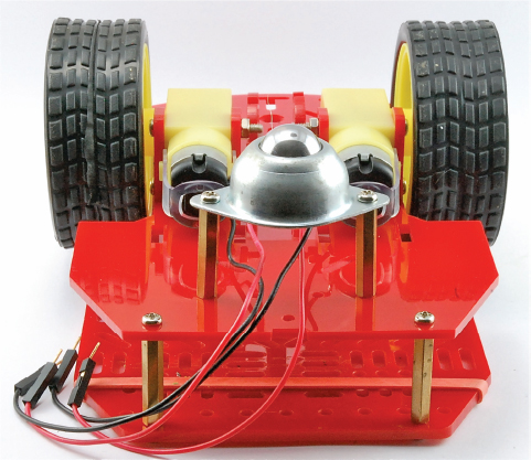
FIGURE 7-32 The Magician Chassis
Step 2. Program the Arduino
It is a good idea to program the Arduino with the sketch before you start attaching the electronics. Load the sketch “rover” onto the Arduino.
Step 3. Attach the Arduino and Breadboard
Find suitable mounting holes on the chassis and use small nuts and bolts to attach the Arduino. You can also use an elastic band for this. Some breadboards come with a self-adhesive backing, and you can use this to attach it to the chassis. For a less permanent way of attaching it, a rubber band will work just fine.
Step 4. Build the Breadboard
Figure 7-33 shows the breadboard layout for the project and how it is wired up to the Arduino.
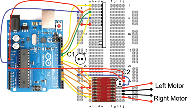
FIGURE 7-33 Breadboard layout for the rover
There are quite a lot of wires on this project, so check all the connections once you think you have finished. Photocopying the page of the book and checking off with a pencil each connection as it’s made is a good way of ensuring they are all there.
Also, not unlike our normal large breadboard, when wiring up this breadboard we have used the outer supply rail as GND and the inner rail as 5V.
Step 5. Wire up the Motors
Each motor has a red and a black lead. So find the leads going to the left motor and attach them to the breadboard rows connected to the A01 and A02 connections of the motor module. Then, do the same for the right motor, connecting them to B01 and B02.
Step 6. Attach the Battery
If the battery box is made up of two rows of batteries, it will be quite a snug fit and the top surface of the chassis will need to bend out a little to accommodate it. If it is all in one row, like the Adafruit box, then you can attach it to the bottom layer of the chassis using small nuts and bolts.
Testing
When everything is assembled and ready to go, attach the battery and try the project out by pressing the buttons on the remote. The C button will set the robot running forwards, the B button will make it rotate to the right on the spot, and D will make it turn to the left. The A button will bring the robot to a halt.
Software
The sketch for this project is too long to list in full here, so we will just look at some of the main points.
The RF receiver toggles the output for the button you press. So press it once and it turns on, press it again and it turns off. However, this is not really the way we want it to work. We just want to know when a button has been pressed.
To do that, we keep track of the last state of each of the outputs, and only when the output has changed do we report the change. This uses the following array to store the output states and another array “remotePins”:
The function that detects that a change has occurred is as follows:

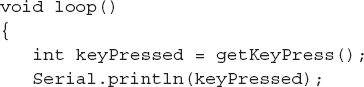
The main loop calls this function to detect any key presses and then calls the appropriate function for the button.
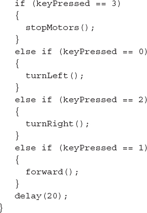
The functions that control the movement are all very similar. The function for turning left is shown next.
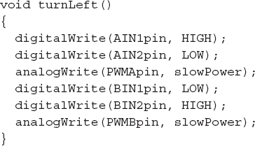
This sets the AIN and BIN pins—in this case, to set the motors turning in opposite directions. The PWM power is controlled by a call to “analogWrite” using one of two values held in variables (“fullPower” and “slowPower”).
How to Use a Seven-Segment LED Display Module
Seven-segment LED displays have a nice retro feel to them.
LED displays made up of a number of LEDs contained in a single package can be a challenge to control. Such displays will normally be controlled using a microcontroller; however, it is not necessary to use a microcontroller output pin to each individual LED. But rather, multi-LED displays are organized as “common anode” or “common cathode,” with all the LED terminals of the anode or cathode connected together and then brought out through one pin. Figure 7-34 shows how a common cathode seven-segment display might be wired internally.
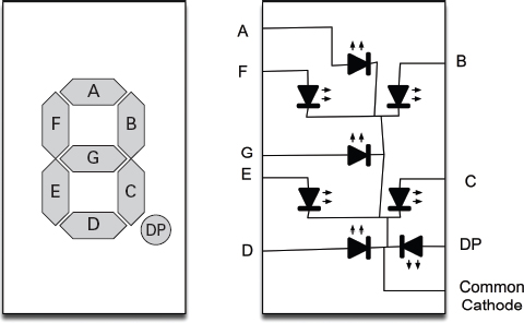
FIGURE 7-34 A common cathode LED display
In a common cathode display like this, the common cathode would be connected to ground and each segment anode driven by a microcontroller pin through a separate resistor. Do not be tempted to use one resistor on the common pin, and don’t use any resistors on the non-common connections, since the current will be limited no matter how many LEDs are lit. Because of this, the display will get dimmer the more LEDs are illuminated.
It is quite common for multiple displays to be contained in the same case—for example, the three-digit, seven-segment common cathode LED display shown in Figure 7-35.

FIGURE 7-35 A three-digit, seven-segment LED display
In this kind of display, each digit of the display is like the single-digit display of Figure 7-35, and has its own common cathode. In addition, all the A segment anodes are connected together, as are each segment.
The Arduino using the display will then activate each common cathode in turn and then turn on the appropriate segments for that digit, and then move onto the next digit, and so on. This refresh happens very quickly so that the display appears to display different numbers on each digit. This is called multiplexing.
Note the use of transistors to control the common cathodes. This is simply to handle the current of potentially eight LEDs at once, which would be too much for most microcontrollers.
Fortunately for us, there is a much simpler way to use multi-digit, seven-segment LED displays. Modules ride to the rescue once again!
Figure 7-36 shows a four-digit, seven-segment LED display that has just four pins on its connector, and two of them are for power.

FIGURE 7-36 A four-digit, seven-segment I2C display
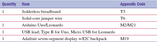
You Will Need
To build this, you will need the following items.
Construction
The module comes as a kit, so start by following the instructions that accompany the module to assemble it.
The LED module uses a type of serial interface on the Arduino called I2C (pronounced “I squared C”). This requires just two pins, but they have to be the two pins above “AREF” on the Arduino Uno. These pins are named SDA and SCL.
This means that, frustratingly, the module will not just plug straight into the Arduino, we will need to use breadboard.
Figure 7-37 shows the breadboard layout and Figure 7-38 the breadboard itself, with the seven-segment display in action.
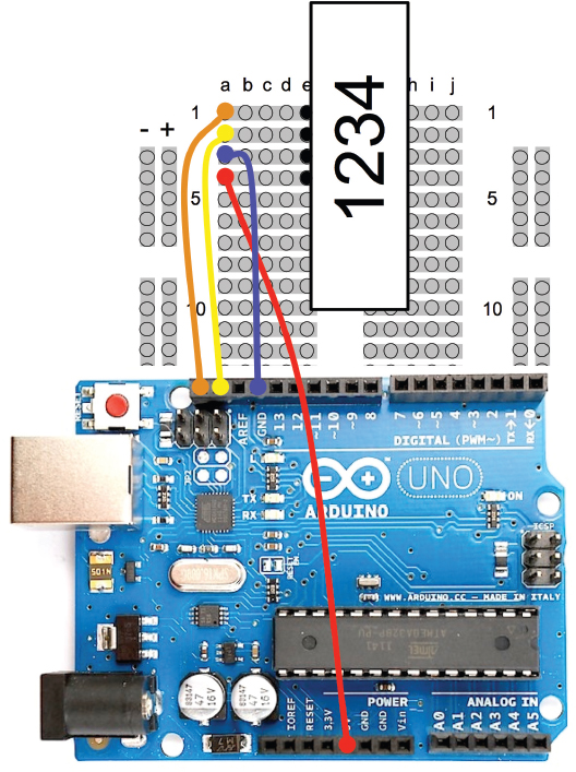
FIGURE 7-37 Breadboard layout for using the seven-segment display
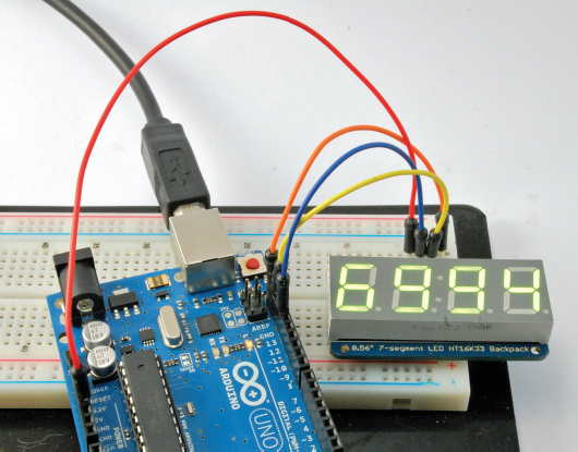
FIGURE 7-38 The seven-segment display in action
Software
Adafruit provides a library to simplify the use of the module. You need to download this and copy the library folder into the “libraries” folder in your Arduino documents folder. See the instructions on Adafruit’s web site at www.adafruit.com/ products/880.
The three libraries that the module requires are loaded using the #includes statements.
The following line assigns a variable to the display object so we can tell it what to display.
The “setup” function begins serial communication on the I2C pins and then initializes the display. The value 0x70 is the I2C address of the display module. This is the default value for its address, but there are solder connections on the module you can short together to change the address. You might want to do this if you need to use more than one display, since each display must have a different address.

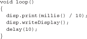
The “loop” function simply displays the current number of milliseconds since the board was reset, divided by 10. The display will therefore count up in 1/100ths of a second.
How to Use a Real-Time Clock Module
You could write an Arduino sketch to keep track of the time, but as soon as you unplugged it, it would forget the time. The way around this problem is to use an RTC (real-time clock) like the one shown in Figure 7-39.
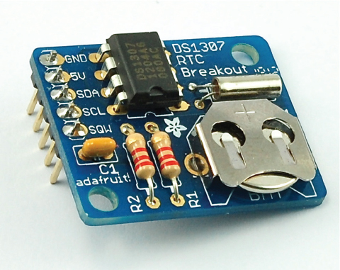
FIGURE 7-39 An RTC module
This particular module is also an Adafruit product. There are lots of similar modules out there, but their pin allocations may be different.
The RTC includes a lithium battery that will last for years, and provides enough power to keep the correct time when the module is not powered.
We can combine the RTC module with the seven-segment display module we used previously and make ourselves a simple digital clock (Figure 7-40).
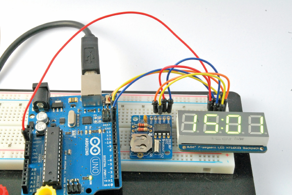
FIGURE 7-40 A “simple” digital clock
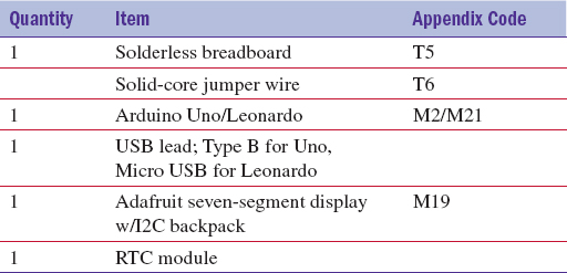
You Will Need
To build this, you will need the following items.
Construction
The RTC module also comes as a kit, so start by following the instructions that accompany the module to assemble it.
The RTC module also uses I2C and has a different address to the display, so we do not need to change anything.
Figure 7-41 shows the breadboard layout for the clock.
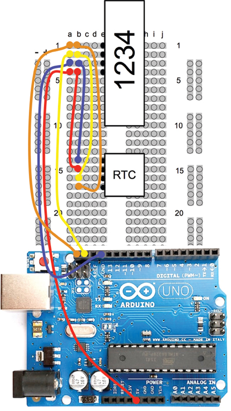
FIGURE 7-41 Breadboard layout for the clock
Software
Load up the sketch “clock” onto your Arduino. The display should immediately start showing the time your computer is set to.
Much of this sketch is the same as that in the section “How to Use a Seven-Segment LED Display Module.” But there is one additional library for the RTC module that we need to import. Instructions for downloading this are linked from the product page for the RTC module (www.adafruit.com/products/264).

In addition to creating a display to use, we now have to give the RTC a name. Let’s call it “RTC”.
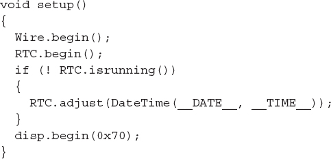
The “setup” function now has an additional command to start the RTC so it is ready to receive commands. The “if” statement checks to see if the clock part of the RTC is active. If this is the first time it has been used, it will not be, so if this is the case, it initializes it to the programming computer’s time.
The main loop now reads the time from the RTC and displays it. It also uses the display libraries’ “drawColon” function to make the colon flash by turning it on and off with a half-second delay in between.
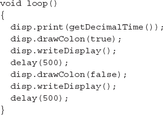
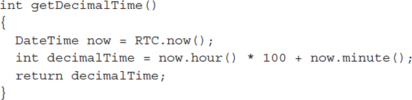
The “getDecimalTime” function reads the hours and minutes from the RTC and turns them into a decimal number that can be written to the display. The first two digits will contain the hour, and the left two digits the minute.
Summary
In addition to the modules here, you will find lots of other useful modules on the web sites of companies like Adafruit and SparkFun. The web sites also include some information on how to use the modules and their specifications. If you find a module you would like to make use of, the first step is to research how you could use it. As well as the datasheets and tutorial information on the supplier’s web site, you will often find instructions on building the projects if you search for the module on the Internet.
..................Content has been hidden....................
You can't read the all page of ebook, please click here login for view all page.