

Architectural and technical description
Today, the number of sources generating data is leading to an exponential growth in the data volume. Making sense of this data, and doing it faster than the competition can, leads to an unprecedented opportunity to gain valuable insights and apply them at the best point of impact to improve your business results.
The Power LC921 server is the dense 1U server design that delivers Peripheral Component Interconnect Express (PCIe) Gen4 and Coherent Accelerator Processor Interface (CAPI) 2.0 for superior scaling efficiency.
The Power System LC922 server delivers superior performance and meets the open source workload data requirements that are being driven by the AI era or modern data platforms (for example, MariaDB, MongoDB, PHP, Hortonworks, PostgreSQL, and NoSQL). It is the server of choice for clients that want compute capabilities that are enabled by IBM POWER9 processors, scaling efficiency with the POWER9 advanced I/O, and ample storage capacity to contain the AI data volumes. Additionally, the server is simple to order and cost-optimized, and can scale from single racks to large clusters with a simple deployment.
1.1 Power LC921 hardware overview
The Power LC921 server delivers superior performance, scaling efficiency, and density that meets the requirements that are demanded by the AI era. It is the server of choice for clients that want industry-leading computation with up to two POWER9 processors in a dense 1U server design that delivers PCIe Gen4 and CAPI 2.0 for superior scaling efficiency.
The Power LC921 server, a dense server design, is shown in Figure 1-1.

Figure 1-1 IBM Power LC921 1U system
The Power LC921 server supports one or two processor sockets, offering 16-core (2.2 GHz base frequency) or 20-core (2.13 GHz base frequency) POWER9 processor-based configurations in a 19-inch rack-mount, 1U (EIA units) drawer configuration. No mixing of processors is supported.
Base processor frequencies are typically exceeded under workloads. The maximum frequency boost is 3.8 GHz, and achievable under most workload and environmental conditions.
Each chip supports 512 KB L2 cache per core and 120 MB L3 cache per chip.
The Power LC921 server provides two hot-swap and redundant power supplies and two, four, six, eight, 12, or 16 RDIMM memory slots. Supported memory features are 16 GB (#EKMF), 32 GB (#EKMG), and 64 GB (#EKMD). No mixing of memory is allowed. The server supports a maximum of 1 TB memory.
The Power LC921 server also offers:
•Superior throughput and performance for high-value Linux workloads.
•Low acquisition cost through system optimization (industry-standard memory and 3-year warranty).
•Powerful I/O options in the system unit, including:
– Two PCIe G4 x16 full-height and full-length slots, CAPI 2.0-enabled.
– One PCIe G4 x8 low-profile (LP) slot.
– One PCIe G4 x8 LP slot, CAPI-2.0 enabled (internal).
•Four 3.5” large form factor (LFF)/2.5” small form factor (SFF) bays for four SAS/SATA hard disk drives (HDDs) or solid-state drives (SSDs) or 2.5” four bays available for Non-Volatile Memory Express (NVMe) Gen3 adapters.
•Two SATA Disk on Module (DOM) connectors on the system board (for optional local, captive flash devices for operating system (OS) boot).
•Integrated MicroSemi PM8069 SAS/SATA 16-port Internal Storage Controller PCIe3.0 x8 with RAID 0, 1, 5, and 10 support (no write cache):
– The Integrated SAS/SATA controller (PM8069) does not support 4 K disks (SSD or HDD). Selecting a 4 K HDD requires an LSI host bus adapter (HBA). SSDs must be formatted by the client to 512-byte sectors for RAID.
– The Integrated SAS/SATA controller (PM8069) does not have a self-encrypting drive (SED) feature, but can use unlocked SED drives.
•Integrated Intel XL710 Quad Port 10 GBase-T PCIe3.0 x8 UIO built-in local area network (LAN) (one shared management port).
•Includes Trusted Platform Module (TPM) 2.0 Nuvoton NPCT650ABAWX through a I2C (for secure boot and trusted boot).
•Dedicated 1 Gb Intelligent Platform Management Interface (IPMI) port.
•Two rear USB 3.0 ports.
•Rear VGA port
•19-inch rack-mount 1U configuration.
•Supported operating systems:
– Red Hat Enterprise Linux (RHEL) 7.5 Little Endian (POWER9), or later.
– Ubuntu Server 18.04 LTS.
1.2 Power LC922 hardware overview
The Power LC922 server supports one or two processor sockets, offering 16-core (2.91 GHz base frequency) or 20-core (2.70 GHz base frequency) or 22-core (2.6 GHz base frequency) POWER9 processor-based configurations in a 19-inch rack-mount.
Base processor frequencies are typically exceeded under workloads. The maximum frequency boost is 3.8 GHz, and achievable under most workload and environmental conditions.
It has a 2U (EIA units) drawer configuration. No mixing of processors is allowed.
The Power LC922 server provides two hot-swap and redundant power supplies, and two, four, six, eight, 12, or 16 DIMM memory slots. Supported memory features are 16 GB (#EKMF), 32 GB (#EKMG), and 64 GB (#EKMD). No mixing of memory is allowed.
The Power LC922 server is shown in Figure 1-2.

Figure 1-2 IBM Power LC922 server 2U form factor
The Power LC922 server also offers:
•Superior throughput and performance for high-value Linux workloads.
•Low acquisition cost through system optimization (industry-standard 3-year warranty).
•Powerful IBM POWER9 single-chip module (SCM) processors that offer 2.9 GHz,
2.7 GHz, or 2.6 GHz performance with 16, 20, or 22 single-socket and 32, 40, or 44 fully activated cores. No mixing of processors is allowed.
2.7 GHz, or 2.6 GHz performance with 16, 20, or 22 single-socket and 32, 40, or 44 fully activated cores. No mixing of processors is allowed.
•Up to 1024 GB (1 TB) of DDR4 memory.
•Rich I/O options in the system unit, including:
– Two PCIe G4 x16 full-height and full-length slots, CAPI-2.0 enabled.
– Three PCIe G4 x8 full-height and full-length slots, one CAPI-2.0 enabled (all physically x16).
– One PCIe G4 x8 LP slot.
•Two full-height and full-length GPU-capable slots.
|
Note: At the time of writing the is no GPU available for order.
|
•Twelve LFF/SFF bays for 12 SAS/SATA HDDs or SSDs, with four that are available for NVMe Gen3 adapters.
•Includes TPM 2.0 Nuvoton NPCT650ABAWX through I2C (for secure boot and trusted boot).
•Integrated MicroSemi PM8069 SAS/SATA 16-port Internal Storage Controller PCIe3.0 x8 with RAID 0, 1, 5, and 10 support (no write cache):
– The Integrated SAS/SATA controller (PM8069) does not support 4 K disks (SSD or HDD). Selecting a 4 K HDD requires an LSI HBA. SSDs must be formatted by the client to 512-byte sectors for RAID.
– The Integrated SAS/SATA controller (PM8069) does not have a SED feature, but can use unlocked SED drives.
•Two SATA DOM connectors on the system board (for optional local, captive flash devices for OS boot).
•Optional two SFF drive trays in the rear for SAS/SATA (physically blocks off 16 trays for the first CPU when installed). They are controlled only by the integrated MicroSemi PM8069.
•Integrated Intel XL710 Quad Port 10 GBase-T PCIe3.0 x8 UIO built-in LAN (one shared management port).
•Dedicated 1 Gb IPMI port.
•Two rear USB 3.0 ports.
•Rear VGA port.
•19-inch rack-mount 2U configuration.
•OSes:
– RHEL 7.5 Little Endian (POWER9) or later.
– Ubuntu Server 18.04 LTS.
1.2.1 Minimum features
The Power LC921 server has by default an NVMe system board, and the Power LC922 server has two drive backplane options, both of which are NVMe-capable. The default drive backplane directly connects SAS/SATA to the integrated MicroSemi PM8069, and the optional drive backplane includes an LSI expander (SAS3x28R) to allow connection of all 12 SAS/SATA disks to one of several LSI HBA options. The system selection determines whether the system accepts one or two processors along with the backplane.
The minimum Power LC921 or Power LC922 initial order must include one processor module, two memory DIMMs of 16 GB capacity, two power cords, rack-mounting hardware, a system software indicator, a rack integrator specify, and a Language Group Specify. Linux is the OS.
Table 1-1 shows the minimum configuration for the Power LC921 server.
Table 1-1 Power LC921 minimum configuration
|
Feature code
|
Description
|
|
#EKP6
or
#EKP7
|
One 16-core 2.2 GHz POWER9 processor
One 20-core 2.13 GHz POWER9 processor
|
|
#EKMF
|
Two 16 GB DIMMs, 2666 MHz DDR4 DRAM
|
|
#4650
|
One Rack Indicator - Not Factory Integrated
|
|
#EKBB
|
One 1-Socket 1U LFF NVMe Fab Assembly
|
|
#2147
|
One Primary OS Linux
|
|
#9xxx
|
Language Group Specify (select one from the announced features.)
|
Table 1-2 shows the minimum configuration for the Power LC922 server.
Table 1-2 IBM system LC922 minimum configuration
|
Feature code
|
Description
|
|
#EKPD
or
#EKPC
or
#EKPE
|
One 16-core 2.91 GHz POWER9 processor
One 20-core 2.7 GHz POWER9 processor
One 22-core 2.6 GHz POWER9 processor
|
|
#EKMF
|
Two 16 GB DIMMs, 2666 MHz DDR4 DRAM
|
|
#4650
|
One Rack Indicator - Not Factory Integrated
|
|
#EKBF
|
ONe 1-Socket 2U 12x LFF/SFF 4 NVMe Direct Attach Fab Assembly
|
|
#2147
|
One Primary OS Linux
|
|
#9xxx
|
Language Group Specify (select one from the announced features.)
|
|
Note: If a rack is needed, it must be ordered as a machine type and model (MTM) rack with initial system orders. If the rack is included on the same system order, it will be shipped at the same time in the same shipment, but in separate packing material. IBM does not offer IBM Manufacturing rack integration of the server into the rack before shipping at this time.
|
1.3 Operating system support
The Power LC921 and Power LC922 servers support Linux, which provides a UNIX like implementation across many computer architectures.
For more information about the software that is available on Power Systems, see Linux on Power Systems.
1.3.1 Ubuntu
Ubuntu Server 18.04.5 LTS for POWER9 is supported on the servers with support for later distributions as they become available.
For more information about Ubuntu Server for Ubuntu for POWER9, see Ubuntu Server for IBM POWER.
1.3.2 Red Hat Enterprise Linux
RHEL (ppc64le) Version 7.5 pp64le is supported on the server with support for later distributions as they become available.
For more questions about this release and supported Power Systems servers, see the Red Hat Hardware Catalog.
1.4 Operating environment
The Power LC921 and Power LC922 servers can operate at nominal processor frequencies within the ASHRAE A2 envelope.
|
Note: ASHRAE is a global society that provides standards for environmental measures. For more information, see ASHRAE.
|
Figure 1-3 shows the values and different levels of ASHRAE for humidity.

Figure 1-3 ASHRAE levels for humidity
Figure 1-4 shows levels for altitude and temperature.

Figure 1-4 ASHRAE levels for temperature and altitude
For more information about ASHRAE A2, see:
1.5 Physical package
The Power LC921 server is offered exclusively as a rack-mounted 1U server. The width, depth, height, and weight of the server are shown in Table 1-3.
Table 1-3 Physical dimensions for the Power LC921 server
|
Dimension
|
Power LC921 server
|
|
Width
|
441.5 mm (17.4 inches)
|
|
Depth
|
822 mm (32.4 inches)
|
|
Height
|
43 mm (1.7 inches)
|
|
Weight (maximum configuration)
|
13.38 kg (29.5 lbs)
|
The Power LC922 server is offered exclusively as a rack-mounted 2U server. The width, depth, height, and weight of the server are shown in Table 1-4.
Table 1-4 Physical dimensions for the Power LC922 server
|
Dimension
|
Power LC922 server
|
|
Width
|
441.5 mm (17.4 inches)
|
|
Depth
|
822 mm (32.4 inches)
|
|
Height
|
89 mm (3.5 inches)
|
|
Weight (maximum configuration)
|
25 kg (56 lbs)
|
|
Note: The weight of these servers does not include the weight of the HDDs.
|
1.6 System architecture
These servers balance processor performance, storage capacity, memory capacity, memory bandwidth, and PCIe adapter allowance to maximize price performance for big data workloads.
Figure 1-5 illustrates the block diagram of the Power LC921 server.

Figure 1-5 Power LC921 server logical system diagram
Figure 1-6 illustrates the block diagram of Power LC922 server.

Figure 1-6 Power LC922 server logical block diagram
Bandwidths that are provided throughout the section are theoretical maximums that are used for reference.
The speeds that are shown are at an individual component level. Multiple components and application implementation are key to achieving the preferred performance. Always do the performance sizing at the application workload environment level and evaluate performance by using real-world performance measurements and production workloads.
Table 1-5 lists the feature codes for the Power Systems LC921 system board.
Table 1-5 Power Systems LC921 system board
|
Feature code
|
Description
|
|
#EKBB
|
1-Socket 1U LFF NVMe Fab Assembly
|
|
#EKBC
|
2-Socket 1U LFF NVMe Fab Assembly Base
|
Table 1-6 shows the available processors for the Power Systems LC921 server.
Table 1-6 Available processors for the Power Systems LC921 server
|
Feature code
|
Description
|
|
#EKP6
|
16-core 2.2 GHz POWER9 processor
|
|
#EKP7
|
20-core 2.13 GHz POWER9 processor
|
The number of processors in the system is determined by the base system that is selected.
Table 1-7 shows the available system boards for the Power LC922 server.
Table 1-7 Power System LC922 system board
|
Feature code
|
Description
|
|
#EKBF
|
1-Socket 2U 12 LFF/SFF 4 NVMe Direct Attach Fab Assembly
|
|
#EKBG
|
2-Socket 2U 12 LFF/SFF 4 NVMe Direct Attach Fab Assembly
|
|
#EKBH
|
1-Socket 2U 12 LFF/SFF 4 NVMe LSI Expander Assembly (SAS3x28R)
|
|
#EKBJ
|
2-Socket 2U 12 LFF/SFF 4 NVMe LSI Expander Assembly (SAS3x28R)
|
Table 1-8 shows the available processors for the Power LC922 server.
Table 1-8 Available processor for the Power System LC922 server
|
Feature code
|
Description
|
|
#EKPD
|
16-core 2.9 GHz POWER9 processor
|
|
#EKPC
|
20-core 2.7 GHz POWER9 processor
|
|
#EKPE
|
22-core 2.6 GHz POWER9 processor
|
The number of processors in the system is determined by the base system that is selected.
|
Note: A 1-socket board cannot be upgraded to a 2-socket board.
|
The Power System LC922 server is composed of a base system with an infrastructure that is determined by the number of needed processors and support for NVMe drives. The base system selection determines whether the system accepts one or two processors. The base system selection also determines the use of a default drive midplane that supports SAS and SATA drives. All base systems support s NVMe drives in four of the available slots.
Figure 1-7 shows the system board overview and location of CPUs, DIMM, SATA DOM, and TPM.

Figure 1-7 System board overview with CPU, DIMM, SATA DOM, and TPM locations
1.7 The POWER9 processor
This section introduces the current processor in the Power Systems product family and describes its main characteristics and features in general.
The POWER9 processor in the Power LC921 and LC922 servers is the most current generation of the IBM POWER® processor family.
1.7.1 POWER9 processor overview
The IBM POWER9 processor is a super-scalar symmetric multiprocessor (SMP) that is designed for use in servers and large-cluster systems. It supports a maximum SMP size of two sockets and is targeted for high CPU-consuming workloads.
The POWER9 processor offers superior cost and performance benefits. The target market segments are:
•Technical computing
The POWER9 processor provides superior floating-point performance and high-memory bandwidth to address this market segment. It also supports off-chip floating-point acceleration.
•Cloud operating environments
The POWER9 processor enables efficient cloud management software, enforces service-level agreements (SLAs), and provides facilities for chargeback accounting that is based on the resources that are consumed.
•Big data analytics
The POWER9 processor with CAPI-attached large caches and on-chip accelerators provides a robust platform for analytic and big data applications.
•High-performance computing (HPC), high-performance data analysis (HPDA), and artificial intelligence (AI)
1.7.2 Processor features
The POWER9 processor is an SCM that is based on complementary metal–oxide–semiconductor (CMOS) 14-nm technology with 17 metal layers. It is optimized for cloud and data center applications. Within a 50 × 50 mm footprint, designs have four direct-attached memory channels for scale-out configurations. Each DDR4 channel supports up to 2666 Mbps for one DIMM per channel or 2133 Mbps for two DIMMs per channel. Two processors are tightly coupled through two 4 byte, 16 Gbps elastic differential interfaces (EDIs) for SMP. There are 48 lanes of PCIe Gen4 adapters at 16 Gbps.
The POWER9 processor consists of the following main components:
•Twenty-four POWER9 cores, which include both L1 instruction and data caches, shared L2 and L3 caches, and a non-cacheable unit (NCU).
•Each core has up to four threads that use simultaneous multithreading (SMT4).
•On-chip accelerators.
– CAPI 2.0 allows a Field Programmable Gate Array (FPGA) or Application-Specific Integrated Circuit (ASIC) to connect coherently to the POWER9 processor-based SMP interconnect through the PCIe bus.
– On-chip: Compression, encryption, and data moves are initiated by the hypervisor, compression engine, or a Nest Memory Management Unit (NMMU) to enable user access to all accelerators.
– In-core: User invocation encryption (Advanced Encryption Standard (AES) and Secure Hash Algorithm (SHA)).
•Two memory controllers that support direct-attached DDR4 memory:
– Supports four direct-attach memory buses.
– Supports ×4 and ×8, 4 - 16 Gb DRAMs and 3D stacked DRAMs.
•Processor SMP interconnect:
– Supports one inter-node SMP X-bus link.
– Maximum two-socket SMP.
•Three PCIe Controllers (PECs) with 48 lanes of PCIe Gen4 I/O:
– PEC0: One x16 lanes.
– PEC1: Two x8 lanes (bifurcation).
– PEC2: One x16 lane mode or two x8 lanes (bifurcation), or one x8 lanes and two x4 lanes (trifurcation).
– PEC0 and PEC2 support CAPI 2.0.
•Power management.
•Pervasive interface.
From a logical perspective, the POWER9 processor consists of four main components:
•SMP interconnect (also known as an internal fabric interconnect).
•Memory subsystem.
•PCIe I/O subsystem.
•Accelerator subsystem.
Figure 1-8 shows a POWER9 processor with 24 cores.

Figure 1-8 POWER9 processor with 24 cores
1.7.3 Supported technologies
The POWER9 processor supports the following technologies:
•IBM Power Instruction Set Architecture (ISA) Book I, II, and III (Version 3.0)
•Linux on IBM Power Architecture® Platform Reference
•IEEE P754-2008 for binary and decimal floating-point compliant
•Big Endian, little Endian, and strong-ordering support extension
•A 51-bit real address and a 68-bit virtual address
1.7.4 Simultaneous multithreading
The POWER9 processor has improvements in multi-core and multi-thread scaling. A significant performance opportunity comes from parallelizing workloads to enable the full potential of the microprocessor, and the large memory bandwidth. Application scaling is influenced by both multi-core and multi-thread technology.
SMT allows a single physical processor core to dispatch simultaneously instructions from more than one hardware thread context. With SMT, each POWER9 core can present four hardware threads. Because there are multiple hardware threads per physical processor core, more instructions can run at the same time.
SMT is primarily beneficial in commercial environments where the speed of an individual transaction is not as critical as the total number of transactions that are performed. SMT typically increases the throughput of workloads with large or frequently changing working sets, such as database servers and web servers.
Table 1-9 shows a comparison between the different POWER9 processors options for the Power LC921 and Power LC922 servers and the number of threads that are supported by each SMT mode.
Table 1-9 Number of threads supported by Power LC921 and Power LC922 Systems servers
|
Cores per system
|
SMT 0
|
SMT 2
|
SMT 4
|
|
16
|
16 HTpS1
|
32 HTpS
|
64 HTpS
|
|
20
|
20 HTpS
|
40 HTpS
|
80 HTpS
|
|
22
|
22 HTpS
|
44 HTpS
|
88 HTpS
|
|
32
|
32 HTpS
|
64 HTpS
|
128 HTpS
|
|
40
|
40 HTpS
|
80 HTpS
|
160 HTpS
|
|
44
|
44 HTpS
|
88 HTpS
|
176 HTpS
|
1 Hardware Threads per System.
1.7.5 Processor feature codes
The Power LC921and Power LC922 servers support two processor configurations only, as shown in Table 1-10.
Table 1-10 Power LC921 supported processor features codes
|
Feature code
|
Description
|
Minimum
|
Maximum
|
OS support
|
|
#EKP6
|
16-core 2.2 GHz POWER9 processor
|
1
|
2
|
Linux
|
|
#EKP7
|
20-core 2.13 GHz POWER9 processor
|
1
|
2
|
Linux
|
A minimum of one processor module is required with up to a 16-core processor, or a 20-core processor and an extra option of a 22-core processor for Power LC922 servers. No processor activation features are used or orderable on the Power LC921 and Power LC922 servers. All processor cores are always fully activated.
|
Note: The mixing of different processor features on the same system is not allowed.
|
Table 1-11 shows the available processor FCs for the Power LC922 server.
Table 1-11 Power LC922 supported processor features codes
|
Feature code
|
Description
|
Minimum
|
Maximum
|
OS support
|
|
#EKPD
|
16-core 2.9 GHz POWER9 processor
|
1
|
2
|
Linux
|
|
#EKPC
|
20-core 2.7 GHz POWER9 processor
|
1
|
2
|
Linux
|
|
#EKPE
|
22-core 2.6 GHz POWER9 processor
|
1
|
2
|
Linux
|
1.7.6 Coherent Accelerator Processor Interface
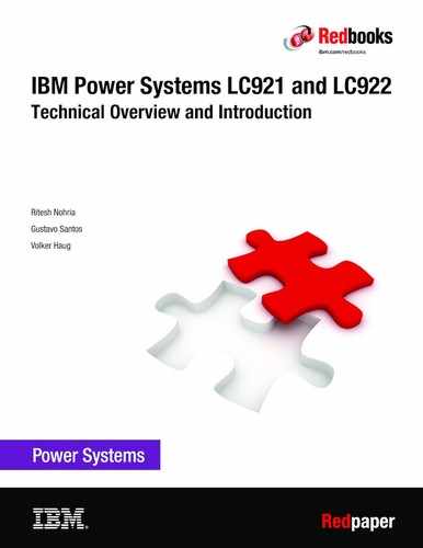
CAPI connects a custom acceleration engine to the coherent fabric of the POWER9 chip. The hybrid solution has a simple programming paradigm while delivering performance well beyond today’s I/O-attached acceleration engines.
Figure 1-9 shows the difference of non-CAPI and CAPI technology and flow of data.
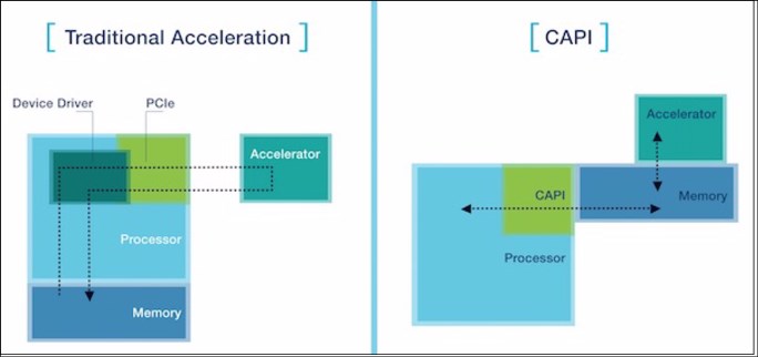
Figure 1-9 Overview of non-CAPI and CAPI technology
CAPI on POWER9 processor-based systems provides a high-performance solution for the implementation of software-specific, computation-heavy algorithms on an FPGA. This innovation can replace either application programs running on core or custom acceleration implementations that are attached through I/O. CAPI removes the complexity of the I/O subsystem, allowing an accelerator to operate as an extension of an application.
The IBM solution enables higher system performance with a much smaller programming investment, allowing heterogeneous computing to be successful across a much broader range of applications.
Because the FPGAs are reconfigured, hardware can be specialized without the traditional costs of hardware fabrication. CAPI enables a customer-defined FPGA solution to be a peer to the POWER9 cores from a memory access (coherent) standpoint.
For more information about CAPI, see CAPI on IBM Power Systems.
1.8 Memory subsystem
The POWER9 memory subsystem consists of a POWER9 processor that supports four channels. Each memory port or channel supports single- or dual-drop industry-standard RDIMMs. The POWER9 processor connects to the DIMMs by using the standard DDR4 memory interface.
Figure 1-10 shows the location of P1’s DIMMs and CPU1 and P2’s DIMMs and CPU2. The DIMM information is the same for both the Power LC921 and Power LC922 servers.

Figure 1-10 DIMM locations on Power LC921 and Power LC922 servers
Table 1-12 shows the supported DIMMs for the Power LC921 and Power LC922 servers.
Table 1-12 Memory feature codes for Power LC921 and Power LC922 servers
|
Feature code
|
Description
|
|
#EKMF
|
16 GB 1RX4 2666 MHz DDR4 RDIMM
|
|
#EKMG
|
32 GB 2RX4 2666 MHz DDR4 RDIMM
|
|
#EKMD
|
64 GB 4RX4 2666 MHz DDR4 3DS RDIMM
|
|
Note: Mixing of DIMMs is not allowed.
|
The POWER9 processor has four channels, and each channel can accommodate a maximum of two DIMMs.
Figure 1-11 shows a single DIMM per channel configuration.

Figure 1-11 Single DIMM per channel configuration
Figure 1-12 shows a dual DIMM per channel configuration.

Figure 1-12 Dual DIMM per channel configuration
1.8.1 DIMM placement rules
Table 1-13 describes the basic rules of DIMMs in the Power LC921 and Power LC922 servers. The minimum memory is 32 GB and maximum is 1 TB. Follow these guidelines:
•For each DDR4 port, the far end, slot 1 must be populated first.
•DIMMs should be plugged into homogeneous groups within port pairs (A and B or
C and D).
C and D).
Table 1-13 DIMM placement rules
|
Slot location
|
Slot
|
DIMM quantity
|
Sequence
|
Comment
|
|
P1-A and P1-B
|
1
|
2
|
1B1
|
Minimum DIMMs that are required for both 1-socket or 2-socket servers.
|
|
P2-A and P2-B
|
1
|
2
|
2A2
|
|
|
P1-C and P1-D
|
1
|
2
|
3
|
Maximum memory bandwidth for a 1-socket server
|
|
P2-C and P2-D
|
1
|
2
|
4Ab
|
Maximum memory bandwidth for a 2-socket server
|
|
P1-A, P1-B, P1-C, and P1-D
|
2
|
4
|
5
|
P1 memory bandwidth reduction due to DDR4 frequency drop
|
|
P2-A, P2-B, P2-C, and P2-D
|
2
|
4
|
6Ab
|
P2 memory BW reduction due to DDR4 frequency drop
|
1 B: Not allowed with an 8 GB DIMM because it does not meet the minimum memory requirement of 32 GB.
2 A: The P2 DIMMs location is the second socket, so P2-A, P2-B, P2-C, and P2-D are not applicable for a 1-socket system.
Figure 1-13 shows the locations of the DIMMs.

Figure 1-13 Physical mapping of the DIMM-to-plug sequence
1.8.2 Memory bandwidth
The memory bandwidth is 170 GBps peak per system in a 2-socket system with 8x RDIMMs single drop, running at 2667 Mbps (136 GBps peak memory bandwidth with all 16x RDIMMs populated, running at 2133 Mbps).
1.9 Internal I/O subsystem
The key components of the I/O subsystem are described in this section.
1.9.1 PCIe Express Controller and PCI Express
The PEC acts as a bridge between the internal processor bus and the high-speed serial (HSS) links that drive the PCI Express I/O. The PEC acts as a processor bus master on behalf of the PCI Express port, converting inbound memory read and write packets into processor bus direct memory access (DMA) traffic. The PEC also acts as a processor bus subordinate, transferring processor load and store commands to the PCI Express devices that are attached to the port.
PCIe uses a serial interface and enables point-to-point interconnections between devices by using a directly wired interface between these connection points. A single PCIe serial link is a dual-simplex connection that uses two pairs of wires, one pair for transmit and one pair for receive, and can transmit only 1 bit per cycle. These two pairs of wires are called a lane. A PCIe link can consist of multiple lanes. In these configurations, the connection is labeled as x1, x2, x8, x12, x16, or x32, where the number is effectively the number of lanes.
The Power LC922 and Power LC921 servers support the new PCIe Gen4 adapters, which are capable of 32 GBps simplex (64 GBps duplex) on a single x16 interface. PCIe Gen4 slots also support previous generation (Gen3 and Gen2) adapters, which operate at lower speeds according to the following rules:
•Place x1, x4, x8, and x16 speed adapters in the same size connector slots first before mixing adapter speed with connector slot size.
•Adapters with smaller link widths are allowed in larger-sized PCIe connectors, but larger width adapters are not compatible with smaller connector sizes (that is, a x16 adapter cannot go in an x8 PCIe slot connector).
|
Note: PCIe x8 adapters use a different type of slot than PCI x16 adapters. If you attempt to force an adapter into the wrong type of slot, you might damage the adapter or the slot.
All but 1x PCIe connector in the Power LC922 server is physically x8; the rest are physically x16, which can accept a x16 card, but have half the bandwidth if the slot is only electrically x8.
|
PCI Gen4 has double the bandwidth from previous generation PCI Gen3 adapters. The x16 PCI Gen4 adapter can handle 256 Gbps data and is ready for a 200 Gbps network connection if such a network becomes available.
Power LC922 or Power LC921 servers can support three different form factors of PCIe adapters:
•PCIe LP cards
•PCIe double-width, full-height and length cards
•PCIe full-height and full-length cards
Before adding or rearranging adapters, use the System Planning Tool to validate the new adapter configuration.
If you are installing a new feature, ensure that you have the software that is required to support the new feature and determine whether there are existing update prerequisites to install. To obtain this information, see Power Systems Prerequisites.
Each POWER9 processor has 48 PCIe lanes running at 32 Gbps full-duplex. The bandwidth formula for server is calculated as follows:
Forty-eight lanes * 2 processors * 16 Gbps * 2 (bidirectional traffic) = 3072 Gbps = 384 GBps
1.9.2 Slot configuration
The Power LC921 server has four PCIe slots, all of which are provided by the PCIe riser cards. Slot 1 is connected to CPU1. PCIe slots 2, 3 and 4 are connected to CPU2. PCIe slots 1, 2, and 3 are CAPI-enabled. PCIe slot 1 (internal only) and 4 are LP slots, and PCIe slots 2 and 3 are full-height and full-width.
|
Note: A double-width, full-height adapter at PCIe slot 2 also occupies PCIe slot 3.
|
Figure 1-14 shows the location of the PCI slots for the Power LC921 server.

Figure 1-14 Power LC921 PCIe slots: Rear view
The Power LC922 server supports up to 6 PCIe slots. PCIe slots 1 and 2 are connected to CPU1. PCIe slots 3, 4, 5, and 6 are connected to CPU2. PCIe slots 2, 3, and 6 are CAPI-enabled. PCIe slot 4 is an LP slot. PCIe slots 1, 5, and 6 are full-height slots. PCIe slots 2 and 3 are double-width, full-height slots.
Figure 1-15 shows the location of the PCI slots for the Power LC922 server.
Figure 1-15 Power System LC922 PCI slots: Rear view
|
Note: A rear HDD tray occupies PCI slot 2, so you cannot install an adapter in PCI slot 2 while you use the rear HDD tray.
|
1.9.3 PCI adapters
This section describes the types and functions of the PCI adapters that are supported by the Power LC921 and Power LC922 servers.
The Power LC921 and Power LC922 servers uses the current PCIe Gen4 technology, which enables 32 GBps unidirectional and 64 GBps bidirectional bandwidth.
This section provides an overview of PCIe and bus speed and feature listings, which are segregated by function, for the supported PCIe adapters in the Power LC921 and Power LC922 servers.
|
Note: PCIe adapters on the Power LC921 and Power LC922 servers are not hot-pluggable.
|
Local area network and InfiniBand adapters
To connect the Power LC921 and Power LC922 servers to a LAN, you can use the LAN adapters that are supported in the PCIe slots of the system in addition to the standard 4-port 10 Gb BaseT Ethernet ports that are present in every system.
Figure 1-16 shows the port numbers of four 10/1/0.1 Gbps RJ45 ports that are integrated into the system.

Figure 1-16 Integrated LAN port numbers
The base system has integrated quad-port 10/1/0.1 Gbps LAN ports. Various other LAN adapters are available, as shown in Table 1-14. Before selecting an adapter, see 1.9.2, “Slot configuration” on page 21.
Table 1-14 LAN and InfiniBand adapters
|
Feature code
|
Description
|
Maximum
|
|
#EKA2
|
Intel 82599ES Ethernet Converged Network Adapter x520-DA2 2-port 10 G/1 G SFP+ PCIe2.0 x8 LP
|
6
|
|
#EKAM
|
Mellanox MCX415A-CCAT ConnectX-4 EN 100 GbE single-port QSFP28 PCIe3.0 x16 LP
|
2
|
|
#EKAU
|
Mellanox MCX4121A-ACAT ConnectX-4 Lx EN 25 GbE dual-port SFP28 PCIe3.0 x8 LP
|
3
|
|
#EKAY
|
Mellanox MCX556A-EDAT ConnectX-5 VPI EDR InfiniBand 100 Gbps and 100 GbE dual-port QSFP28 PCIe4.0 x16 LP
|
2
|
|
#EKF1
|
Mellanox MCX414A-BCAT ConnectX-4 EN dual-port 40/56 GbE QFSP28 PCIe3.0 x8 LP
|
3
|
|
#EKFD
|
Mellanox MCX555A-ECAT ConnectX-5 VPI EDR InfiniBand 100 Gbps and 100 GbE single-port QSFP28 PCIe3.0 x16 LP
|
2
|
|
#EKFF
|
Broadcom 5719 QP 1 G (1 G/100M/10M) Network Interface Card PCIe x4 LP
|
3
|
|
#EKFH
|
Intel XL710 Ethernet Converged Network Adapter 4-port 10 G/1 G SFP+ PCIe3.0 x8 LP
|
3
|
|
#EKFP
|
Intel XL710/X557 10 GBase-T Converged Network Adapter 4-port (10 G/1 G/100M speeds) PCIe3.0 x8 LP
|
3
|
Table 1-15 shows that Intel network adapters require extra system memory. So when you configure the system memory, add the memory along with application sizing.
Table 1-15 Intel network adapters and the requirements for the system memory
|
Feature code
|
Memory consumed per Intel adapter
|
|
#EKFP (4 ports)
|
15 GB
|
|
#EKA2 (2 ports)
|
7.5 GB
|
|
#EKFH (4 ports)
|
15 GB
|
If you use these Intel adapter options, ensure that the total system memory is large enough to meet the adapters memory requirements plus 32 GB, which is the minimum system memory.
Fibre Channel adapters
The servers support a direct or SAN connection to devices that use Fibre Channel connectivity.
Table 1-16 summarizes the available Fibre Channel adapters. All of them have LC connectors. The infrastructure that is used with these adapters determines whether you must procure LC fiber converter cables.
Table 1-16 Fiber adapters
|
Feature code
|
Description (Accessories)
|
|
#EKAF
|
Emulex LPE16002B-M6-O 2-port 16 Gb Fibre Channel card PCIe x8 LP
|
|
#EKFE
|
QLogic QLE2742 32 Gb Fibre Channel adapter PCIe3 x8 2-port LP
|
|
#EKAQ
|
Qlogic QLE2692SR 2-port 16Gb Fibre Channel adapter PCIe3 x8 LP
|
Non-Volatile Memory Express adapters
Table 1-17 shows the NVMe HBAs that may be used in the Power LC921 and Power LC922 servers.
Table 1-17 NVMe host bus adapters
|
Feature code
|
Description
|
|
#EKAG
|
SMC quad-port NVMe Host Bus Adapter (PEX9733) PCIe3.0 x8 LP with cables (1U server)
|
|
#EKNL
|
1600 GB SSD; NVMe; 2.5-inch; PCIe3.0 x4; 5-DWPD
|
|
#EKNR
|
960 GB SSD; NVMe; 2.5-inch; PCIe3.0 x4; 0.8-DWPD
|
|
#EKNN
|
3200 GB SSD; NVMe; 2.5-inch; PCIe3.0 x4; 5-DWPD
|
1.10 Internal storage
The Power LC921 server supports four HDDs or SSDs in the front. The Power LC922 server supports 12 HDDs in the front.
1.10.1 Power LC921 server direct attach drive backplane
The Power LC921 server has four bays of HDDs. All four slots are NVMe-enabled, as shown in Figure 1-17.

Figure 1-17 Four LFF/SFF SAS/SATA Bays (four NVMe-enabled)
1.10.2 Power LC922 server direct attach drive backplane
The Power LC922 server has an integrated PM8069 hard disk controller that supports various SAS/SATA disk options, as shown in Figure 1-18.

Figure 1-18 Integrated hard disk controller: SAS/SAATA drives
Figure 1-19 shows the drive location and numbering to port mapping for the Power LC922 backplane. NVMe drives are supported in positions 0 - 3 of port C through NVMe HBAs.

Figure 1-19 Drive port mapping
The Power LC922 server can accommodate 12 SAS/SATA drives in the front.
Figure 1-20 and Figure 1-21 on page 27 show the various SAS/SATA drive options for the server. An NVMe HBA adapter can accommodate two or four NVMe drives.

Figure 1-20 SAS/SATA drive options for the Power LC922 server

Figure 1-21 Hard disk drive options
Figure 1-22 shows three options with two storage controllers:
•Option 6: There are two controllers present on the server. You may have a total of 12 SAS or SATA HDDs.
•Option 7: There are two controllers present on the server. You may have a configuration of eight HDDs (six HDDs with the first controller and two HDDs with the second controller).
•Option 8: There are a storage controller and a NVMe HBA adapter present on the server. You may have a maximum of eight drives (six HDDs with the first controller and two NVMe drives with the NVMe HBA adapter).

Figure 1-22 Hard disk drive options with two controllers
1.10.3 Power LC922 server: LSI drive backplane
You have the option of using an LSI drive backplane in the Power LC922 server. A maximum of 12 SAS/SATA drives can be installed when you use this backplane.
Table 1-18 shows the maximum number of drives. The number of drives is further reduced when you use NVMe HBAs.
|
Notes:
•Requires an optional LSI HBA and cable kit of either #EKEA, #EKEH or #EKEB.
•This feature is required to access all 12 LFF/SFF drive bays from a single LSI HBA. An LSI HBA accommodates only eight LFF/SFF drive bays with a direct attach feature.
|
Table 1-18 Available SAS/SATA drives
|
Number of allowed SAS/SATAdrives
|
||
|
SAS/SATA controller and 0 - 1 NVMe PCIe HBAs
|
||
|
Zero NVMe HBAs and 0 NVMe Drives
|
One NVMe HBA and + 2 NVMe drives
|
One NVMe HBA and 4 NVMe drives
|
|
12
|
10
|
8
|
Figure 1-23 shows the options for HDDs with an LSI HBA. There are similar options for the LSI HBA when you mix it with an NVMe HBA.

Figure 1-23 Options for disk drives with an LSI storage controller
1.10.4 Disk and media features
The Power LC921 and Power LC922 servers use the Integrated MicroSemi PM8069 SAS/SATA 16-port Internal Storage Controller PCIe3.0 x8 with RAID 0, 1, 5, and 10 support (no write cache). Note the following conditions:
•Selecting a 4 K HDD means that you must use an LSI HBA. SSDs must be formatted by the client to 512-byte sectors for RAID. The Integrated SAS/SATA controller (PM8069) does not support RAID 4 K devices (SSD or HDD). This setup is automatically checked when you place the order and is for informational purposes only.
•An integrated SAS/SATA controller (PM8069) does not have a SED feature. SED drives can be used by the PM0869, but it cannot unlock the encryption feature of those drives.
For 4 K HDDs, use the storage controllers that are shown in Table 1-19 (Power LC921) and Table 1-20 (Power LC922).
Table 1-19 Power LC921 storage controllers
|
Feature code
|
Description
|
|
#EKAA
|
Broadcom (LSI) MegaRAID 9361-8i SAS3 Controller with eight internal ports (1 GB Cache) PCIe3.0 x8 LP with cables
|
|
#EKAB
|
SMC AOC-K-S3008L-L8i 12 Gbps SAS3/RAID 0, 1, and 10 PCIe3.0 x8 LP with cables
|
|
#EKAH
|
Broadcom (LSI) MegaRAID 9361-8i SAS3 Controller with eight internal ports (2 GB Cache) PCIe3.0 x8 LP with cables
|
Table 1-20 Power LC922 storage controllers
|
Feature code
|
Description
|
|
#EKEA
|
Broadcom (LSI) MegaRAID 9361-8i SAS3 Controller with eight internal ports (1 GB Cache) PCIe3.0 x8 LP with cables
|
|
#EKEB
|
SMC AOC-K-S3008L-L8i 12 Gbps SAS3/RAID 0, 1, and 10 PCIe3.0 x8 LP with cables
|
|
#EKEH
|
Broadcom (LSI) MegaRAID 9361-8i SAS3 Controller with eight internal ports (2 GB Cache) PCIe3.0 x8 LP with cables
|
#EKAH and #EKEH are electronically identical. #EKAH is used in a 1U server and #EKEH is used in a 2U server, and this is also true for #EKAA/#EKEA and #EKAB/#EKEB. Only the cables are different for 1U and 2U, which forces different FCs for the kits.
|
Note: The SED drive requires one LSI MegaRAID HBA feature (#EKAA or #EKAH) along with #EKWC (the LSI hardware key) to unlock the LSI SafeStore feature. The SED feature cannot be used with LSI HBA #EKAB or #EKEB or with no adapter.
|
Table 1-21 shows a list of external HBA options to connect JBOD drawers.
Table 1-21 HBA options to connect JBOD drawers
|
Feature code
|
Description
|
|
#EKED
|
Broadcom (LSI) 9300-8E SAS-3 HBA PCIe3.0 x8 LP
|
|
#EKGC
|
Broadcom (LSI) 9305-16E SAS-3 HBA PCIe3.0 x8 LP
|
Table 1-22 provides a list of MES options:
•If no drive is ordered, the front drive bay is filled with #EKT1.
•All drive features include the correct drive carrier, but customers who damage carriers or want to install their own 2.5” (SFF) drives must order MES drive carriers.
Table 1-22 MES options
|
Feature code
|
Description
|
|
#EKT0
|
Tool-less 3.5" to 2.5" Converter Drive Tray
|
|
#EKT1
|
Hot-swap 3.5" HDD Tray with Hollowed Dummy
|
|
#EKT2
|
Tool-less U.2 NVMe 3.5" Drive Tray
|
Table 1-23 and Table 1-24 shows the various options for SATA/SAS HDD/SSD drives.
Table 1-23 SATA controllers that are based on HDDs/SSDs
|
Feature code
|
Description
|
|
#EKS1
|
240 GB 2.5-inch SATA SSD 0.78-DWPD SED
|
|
#EKS3
|
960 GB 2.5-inch SATA SSD 0.6-DWPD NON-SED
|
|
#EKDA
|
2 TB 3.5-inch SATA 6 Gbps 512-Byte HDD NON-SED WrtCache
|
|
#EKDB
|
4 TB 3.5-inch SATA 6 Gbps 512 ByteHDD NON-SED WrtCache
|
|
#EKDD
|
8 TB 3.5-inch SATA 6 Gbps 512 ByteHDD NON-SED WrtCache
|
|
#EKDG
|
10 TB 3.5-inch SATA 6 Gbps 512-Byte HDD NON-SED WrtCache
|
Table 1-24 SAS Controller-based HDDs/SSDs
|
Feature code
|
Description
|
|
#EKS6
|
3.8 TB 2.5-inch SAS SSD 1-DWPD NON-SED
|
|
#EKDQ
|
1.2 TB 2.5-inch 10000 RPM SAS 12 Gbps 512e Byte HDD NON-SED WrtCache
|
|
#EKDR
|
1.8 TB 2.5-inch 10000 RPM SAS 12 Gbps 512e Byte HDD NON-SED WrtCache
|
|
#EKD5
|
HDD; 4 TB; 3.5"; 7200 RPM; SAS; 12 Gbps; 4 K; SED; WrtCache
|
|
#EKD6
|
HDD; 8 TB; 3.5"; 7200 RPM; SAS; 12 Gbps; 4 K; SED; WrtCache
|
|
#EKD1
|
HDD; 2 TB; 3.5"; 7200 RPM; SAS; 12 Gbps; 512e; Non-SED; WrtCache
|
|
#EKD2
|
HDD; 4 TB; 3.5"; 7200 RPM; SAS; 12 Gbps; 512e; Non-SED; WrtCache
|
|
#EKD4
|
HDD; 8 TB; 3.5"; 7200 RPM; SAS; 12 Gbps; 512e; Non-SED; WrtCache
|
|
#EKD8
|
HDD; 10 TB; 3.5"; 7200 RPM; SAS; 12 Gbps; 512e; Non-SED; WrtCache
|
|
#EKDA
|
HDD; 2 TB; 3.5"; 7200 RPM; SATA; 6 Gbps; 512e; Non-SED; WrtCache
|
|
#EKDB
|
HDD; 4 TB; 3.5"; 7200 RPM; SATA; 6 Gbps; 512e; Non-SED; WrtCache
|
|
#EKDD
|
HDD; 8 TB; 3.5"; 7200 RPM; SATA; 6 Gbps; 512e; Non-SED; WrtCache
|
|
#EKDG
|
HDD; 10 TB; 3.5"; 7200 RPM; SATA; 6 Gbps; 512e; Non-SED; WrtCache
|
Table 1-25 shows the available NVMe drives for the Power LC921 and Power LC922 servers.
Table 1-25 Available NVMe drives
|
Feature code
|
Description
|
|
#EKNL
|
1600 GB SSD; NVMe; 2.5-inch; PCIe3.0 x4; 5-DWPD
|
|
#EKNR
|
960 GB SSD; NVMe; 2.5-inch; PCIe3.0 x4; 0.8-DWPD
|
|
#EKNN
|
3200 GB SSD; NVMe; 2.5-inch; PCIe3.0 x4; 5-DWPD
|
Two SATA USB SuperDOMs (SATA DOMs) of 64 GB or 128 GB capacities can be used to boot. You can use them to boot an operating system or to perform other read-intensive operations only.
Figure 1-24 shows the location of a SuperDOM.

Figure 1-24 SuperDOM location
Table 1-26 shows the available SATA DOM options.
Table 1-26 SATA Disk on Module (DOM)
|
Feature code
|
Description
|
|
#EKSK
|
128 GB SATA DOM SuperDOM
|
|
#EKSL
|
64 GB SATA DOM SuperDOM
|
1.10.5 Power LC922 optional 2 x SFF rear SAS/SATA drives
The Power LC922 server can accommodate two SAS/SATA drives at the rear of the server.
Figure 1-25 shows the location of rear drive tray. It is intended for use by the operating system. It occupies PCI slot 2, which is attached to CPU 1. You must order #EKSD to obtain an SFF rear tray.
Figure 1-25 Optional SAS/SATA hot-swap rear drives
|
Note: A single-socket system that uses a rear drive tray has only one PCI slot for an adapter.
The two SFF trays in the rear are controlled only by the integrated MicroSemi PM8069.
|
1.11 System ports
The rears of the Power LC921 and Power LC922 servers have a VGA port, a serial port, an IPMI or BMC port, two USB 3.0 ports, and a quad-port 10/1/0.1 Gbps RJ45 port. They are all integrated into the system board. Both servers support redundant power supply.
Figure 1-26 shows the system ports in the rear view of the Power LC921 server.

Figure 1-26 System ports of the Power LC921 server
Figure 1-27 shows the system ports in the rear view of the Power LC922 server.

Figure 1-27 System ports of the Power LC922 server
These ports are available by default on both servers.
1.12 External I/O subsystems
The Power LC921 and Power LC922 servers do not support I/O drawers.
1.13 IBM Systems Storage
The IBM System Storage™ disk systems products and offerings provide storage solutions with superior value for all levels of business, from entry-level to high-end storage systems. For more information about the various offerings, see IBM Storage.
The following section highlights a few of the offerings.
1.13.1 IBM Flash Storage
The next generation of IBM Flash Storage delivers the extreme performance and efficiency you need. It has a new pay-as-you-go option to reduce your costs and scale on demand. For more information about the hardware and software, see IBM Flash Storage.
1.13.2 Software-defined storage
Software-defined storage (SDS) manages data growth and enables multi-cloud flexibility by providing an agile, scalable, and operations-friendly infrastructure. For more information, see Software-defined storage.
1.13.3 IBM Hybrid Storage
Use IBM Hybrid Storage to optimize your mix of storage media, including flash storage, to achieve the best balance of performance and economics. For more information, see
IBM Hybrid Storage.
IBM Hybrid Storage.
1.13.4 IBM Storage Area Networks
IBM SAN Storage offers a comprehensive portfolio of Fibre Channel SAN switches that support your virtualization, cloud, and big data requirements. For more information, see
IBM SAN Storage.
IBM SAN Storage.
..................Content has been hidden....................
You can't read the all page of ebook, please click here login for view all page.