

General description
The next generation of Power Systems servers with POWER9 technology is built with innovations that can help deliver security and reliability for the data-intensive workloads of today’s enterprises. POWER9 technology is designed from the ground up for data-intensive workloads, such as databases and analytics. Changes in the memory subsystem and the use of industry-standard memory DIMMs take POWER9 technology to the next level by superseding a number of existing price/performance offerings. Designed to run commercial, cognitive, and database workloads, POWER9 technology provides a highly competitive server platform. Client references indicate POWER servers help provide a robust and secure backbone for their IT infrastructure. More companies are using POWER technology in their IT infrastructure, from the shop level to large data center deployments.
The Power S922 server supports two processor sockets, offering 10-core or 20-core typical 2.9 - 3.8 GHz (maximum), 8-core or 16-core typical 3.4 - 3.9 GHz (maximum), or 4-core typical 2.8 - 3.8 GHz (maximum) POWER9 configurations in a 19-inch rack-mount, 2U (EIA units) drawer configuration. All the cores are active. The Power S922 server supports a maximum of 32 DDR4 DIMM slots. Memory features that are supported are 8 GB, 16 GB, 32 GB, 64 GB, and 128 GB, and run at different speeds of 2133, 2400, and 2666 Mbps, offering a maximum system memory of 4096 GB.
The Power S914 server supports one-processor sockets, offering 4-core typical 2.3 - 3.8 GHz (maximum), 6-core typical 2.3 - 3.8 GHz (maximum), or 8-core typical 2.8 - 3.8 GHz (maximum) POWER9 processor-based configurations in a 19-inch rack-mount, 4U (EIA units) drawer or desk-side configuration. All the cores are active. The Power S914 server supports a maximum of 16 DDR4 DIMM slots. Memory features that are supported are 8 GB, 16 GB, 32 GB, and 64 GB, and run at speeds of 2133, 2400, and 2666 Mbps, offering a maximum system memory of 1024 GB.
The Power S924 server supports two processor sockets, offering 8-core or 16-core typical
3.8 - 4.0 GHz (maximum), 10-core or 20-core typical 3.5 - 3.9 GHz (maximum), or 24-core typical 3.4 - 3.9 GHz (maximum) configurations in a 19-inch rack-mount, 4U (EIA units) drawer configuration. All the cores are active. The Power S924 server supports a maximum of 32 DDR4 DIMM slots. Memory features that are supported are 8 GB, 16 GB, 32 GB, 64 GB, and 128 GB, and run at different speeds of 2133, 2400, and 2666 Mbps, offering a maximum system memory of 4096 GB.
3.8 - 4.0 GHz (maximum), 10-core or 20-core typical 3.5 - 3.9 GHz (maximum), or 24-core typical 3.4 - 3.9 GHz (maximum) configurations in a 19-inch rack-mount, 4U (EIA units) drawer configuration. All the cores are active. The Power S924 server supports a maximum of 32 DDR4 DIMM slots. Memory features that are supported are 8 GB, 16 GB, 32 GB, 64 GB, and 128 GB, and run at different speeds of 2133, 2400, and 2666 Mbps, offering a maximum system memory of 4096 GB.
1.1 Systems overview
The following sections provide detailed information about the Power S922, Power S914, and Power S924 servers.
1.1.1 Power S922 server
The Power S922 (9009-22A) server is a powerful one- or two-socket server that ships with up to 20 activated cores. If only one socket is populated at the time of the order, the second socket can be populated later. It has the I/O configuration flexibility to meet today’s growth and tomorrow’s processing needs. This server supports two processor sockets, offering 4-core, 8-core, or 10-core processors running 2.8 - 3.9 GHz in a 19-inch rack-mount, 2U (EIA units) drawer configuration. All the cores are active.
The Power S922 server supports a maximum of 32 DDR4 Registered DIMM (RDIMM) slots. If only one processor socket is populated, then only 16 RDIMMs can be used. The memory features that are supported are 16 GB, 32 GB, 64 GB, and 128 GB, and run at speeds of 1600, 2133, and 2666 MHz, offering a maximum system memory of 2 TB if one socket is single-chip populated and 4 TB with both sockets populated.
The IBM Active Memory™ Expansion feature enables memory expansion by using compression and decompression of memory content, which can effectively expand the maximum memory capacity if extra server workload capacity and performance are available.
Two features are available for the storage backplane:
•#EJ1F: Eight SFF-3 bays with an optional split card (#EJ1H)
•#EC59: Optional PCIe3 Non-Volatile Memory express (NVMe) carrier card with two M.2 module slots
Each of these backplane options uses leading-edge, integrated SAS RAID controller technology that is designed and patented by IBM.
The NVMe option offers fast boot times and is ideally suited for the rootvg of Virtual I/O Server (VIOS) partitions.
The Power S922 server is shown in Figure 1-1.

Figure 1-1 Front view of the Power S922 server
1.1.2 Power S914 server
The Power S914 (9009-41A) server is a powerful one-socket server that ships with up to eight activated cores. It has the I/O configuration flexibility to meet today’s growth and tomorrow’s processing needs. A one-socket system with a 4-core or 6-core POWER9 processor is available in either rack (19-inch rack-mount 4U (EIA units)) or tower configurations. The 8-core higher performance system is available only in a rack configuration.
The Power S914 server supports a maximum of 16 DDR4 error-correcting code (ECC) RDIMM slots. The memory features that are supported are 16 GB, 32 GB, 64 GB, and 128 GB, and run at speeds of 2133 - 2666 MHz, offering a maximum system memory of 1 TB.
If you use the 4-core processor #EP10, the system is limited to four memory DDR4 ECC RDIMMS supporting only the 8_GB RDIMMS (# EM60), 16 GB RDIMMs (#EM62), or the 32 GB RDIMMS (#EM63), which offers a maximum of 64 GB of RAM per system.
The IBM Active Memory Expansion feature enables memory expansion by using compression and decompression of memory content, which can effectively expand the maximum memory capacity if extra server workload capacity and performance are available.
Several different features are available for the storage backplane:
•#EJ1C: Twelve SFF-3 bays with an optional split card (#EJ1E)
•#EJ1D: Eighteen SFF-3 bays/Dual IOA with Write Cache
•#EJ1M: Twelve SFF-3 bays/RDX bays:
– Split feature to 6+6 small form factor (SFF) bays: Add a second SAS Controller.
– Twelve SFF-3 bays/RDX bay/2 EXT PT.
•#EC59: Optional PCIe3 NVMe carrier card with two M.2 module slots
Each of these backplane options uses leading-edge, integrated SAS RAID controller technology that is designed and patented by IBM.
The NVMe option offers fast boot times and is ideally suited for the rootvg of VIOS partitions.
For more information about the NVMe technology, see , “PCIe3 NVMe carrier card with two M.2 module slots (#EC59)” on page 102.
The Power S914 tower server is shown in Figure 1-2.
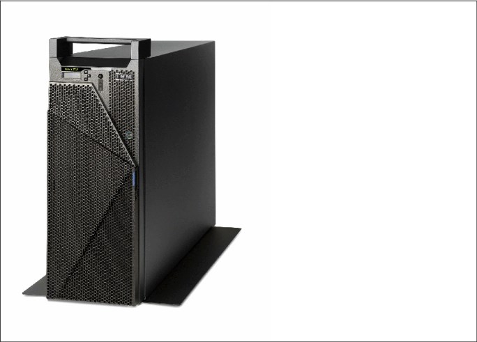
Figure 1-2 The Power S914 tower
1.1.3 Power S924 server
The Power S924 (9009-42A) server is a powerful one- or two-socket server that ships with up to 24 activated cores. It has the I/O configuration flexibility to meet today’s growth and tomorrow’s processing needs. This server supports two processor sockets, offering 8 or 16 cores at 3.8 - 4.0 GHz, 10 or 20 cores at 3.5 - 3.9 GHz, or 24 cores at 3.4 - 3.9 GHz. The systems are 19-inch rack-mount, 4U (EIA units) drawer configuration. All the cores are active.
The Power S924 server supports a maximum of 32 DDR4 RDIMM slots per processor socket that is populated. The memory features that are supported are 16 GB, 32 GB, 64 GB, and 128 GB, offering a maximum system memory of 4 TB.
The Active Memory Expansion feature enables memory expansion by using compression and decompression of memory content, which can effectively expand the maximum memory capacity if more server workload capacity and performance are available.
Several different features are available for the storage backplane:
•#EJ1C: Twelve SFF-3 bays with an optional split card (#EJ1E)
•#EJ1D: Eighteen SFF-3 bays/Dual IOA with Write Cache
•#EJ1M: Twelve SFF-3 bays/RDX bays:
– Split feature to 6+6 SFF bays: Add a second SAS Controller.
– Twelve SFF-3 bays/RDX bay/2 EXT PT.
•#EC59: Optional PCIe3 NVMe carrier card with two M.2 module slots
Each of the three backplane options uses leading-edge, integrated SAS RAID controller technology that is designed and patented by IBM.
The Power S924 server is shown in Figure 1-3.

Figure 1-3 Front view of the Power S924 server
1.1.4 Common features
Many features are common to all of the servers being considered in this book, and some of them are described in this section.
There is no internal DVD
There is no internal DVD option, although an external USB DVD drive is available as #EUA5. Customers are encouraged to use USB flash drives to install operating systems and VIOS whenever possible because they are much faster than DVD.
The operator panel
The operator panel is now composed of two parts. All of the servers have the first part, which provides the power switch and LEDs, as shown in Figure 1-4.

Figure 1-4 Operator panel: Power switch and LEDs
The second part is an LCD panel with three buttons, as shown in Figure 1-5.

Figure 1-5 Operator panel: LCD and switches
The LCD panel is mandatory in the Power S914 Tower. It is also required if the server runs IBM i. In the Power S914, Power S922, and Power S924 rack-mounted servers, it is optional, but if a rack contains any of these servers, one of the them must have an LCD panel.
The LCD panel can be moved (by using the correct procedure) from one server to another server, which enables appropriate service to be carried out.
1.2 Operating environment
Table 1-1 lists the electrical characteristics for the servers.
Table 1-1 Electrical characteristics for Power S922, Power S914, and Power S924 servers
|
Electrical characteristics
|
Properties
|
||
|
Power S922 server
|
Power S914 server
|
Power S924 server
|
|
|
Operating voltage
|
1400 W power supply: 200 - 240 V AC
|
900 W power supply: 100 - 127 V AC or
200 - 240 V AC 1400 W power supply: 200 - 240 V AC
|
1400 W power supply: 200 - 240 V AC
|
|
Operating frequency
|
47/63 Hz
|
47/63 Hz
|
47/63 Hz
|
|
Thermal output
|
6,416 Btu/hour (maximum)
|
5,461 Btu/hour (maximum)
|
9,386 Btu/hour (maximum)
|
|
Power consumption
|
1880 watts (maximum)
|
1600 watts (maximum)
|
2750 watts (maximum)
|
|
Power-source loading
|
1.94 kVa (maximum configuration)
|
1.65 kVa (maximum configuration)
|
2.835 kVa (maximum configuration)
|
|
Phase
|
Single
|
Single
|
Single
|
|
Note: The maximum measured value is the worst-case power consumption that is expected from a fully populated server under an intensive workload. The maximum measured value also accounts for component tolerance and non-ideal operating conditions. Power consumption and heat load vary greatly by server configuration and utilization. The IBM Systems Energy Estimator should be used to obtain a heat output estimate that is based on a specific configuration.
|
Table 1-2 lists the environment requirements for the servers.
Table 1-2 Environment requirements for Power S922, Power S914, and Power S924 servers
|
Environment
|
Recommended operating
|
Allowable operating
|
Non-operating
|
|
Temperature
|
18 - 27°C
(64.4 - 80.6°F) |
5 - 40°C (41 - 104°F)
|
5 - 45°C (41 - 113°F)
|
|
Humidity range
|
5.5°C (42°F) dew point (DP) to 60% relative humidity (RH) or 15°C (59°F) dew point
|
8% - 85% RH
|
8% - 80% RH
|
|
Maximum dew point
|
N/A
|
24°C (75°F)
|
27°C (80°F)
|
|
Maximum operating altitude
|
N/A
|
3050 m (10000 ft)
|
N/A
|
Table 1-3 lists the noise emissions for the systems
Table 1-3 Noise emissions for Power S922, Power S914, and Power S924 servers
|
Product
|
Declared A-weighted sound power level, LWAd (B)
|
Declared A-weighted sound pressure level, LpAm (dB)
|
||
|
Operating
|
Idle
|
Operating
|
Idle
|
|
|
Power S922 server
|
7.8
|
6.9
|
61
|
53
|
|
Power S914 (tower) server
|
5.8
|
5.3
|
39
|
34
|
|
Power S914 (rack) server
|
5.9
|
5.3
|
41
|
34
|
|
Power S924 server
|
6.4
|
5.2
|
46
|
34
|
|
Tip:
•Declared level LWad is the upper-limit A-weighted sound power level. Declared level LpAm is the mean A-weighted emission sound pressure level that is measured at the 1-meter bystander positions.
•All measurements are made in conformance with ISO 7779 and declared in conformance with ISO 9296.
•10 dB (decibel) equals 1 B (bel).
|
1.3 Physical package
The Power S914 server is available in both rack-mount and tower form factors. The
Power S922 and Power S924 servers are available in rack-mount form factor only.
Power S922 and Power S924 servers are available in rack-mount form factor only.
1.3.1 Tower model
Table 1-4 shows the physical dimensions of the Power S914 tower chassis.
Table 1-4 Physical dimensions of the Power S914 tower chassis
|
Dimension
|
Power S914 server (9009-41A)
|
|
Width
|
182.4 mm (7.18 in.)
|
|
Width with stand
|
328.5 mm (12.93 in.)
|
|
Depth
|
751.7 mm (29.59 in.)
|
|
Depth with front-rotatable door
|
814.7 mm (32.07 in.)
|
|
Height
|
486.1 mm (19.14 in.)
|
|
Height with handle
|
522 mm (20.55 in.)
|
|
Weight
|
46.94 kg (103.5 lb)
|
1.3.2 Rack-mount model
Table 1-5 shows the physical dimensions of the Power S922 rack-mounted chassis. The server is available only in a rack-mounted form factor and takes 2U (2 EIA units) of rack space.
Table 1-5 Physical dimensions of the Power S922 rack-mounted chassis
|
Dimension
|
Power S922 server (9009-22A)
|
|
Width
|
482 mm (18.97 in.)
|
|
Depth
|
766.5 mm (30.2 in.)
|
|
Height
|
86.7 mm (3.4 in.)
|
|
Weight
|
30.4 kg (67 lb)
|
Figure 1-6 show the front view of the Power S922 server.

Figure 1-6 Front view of the Power S922 server
Table 1-6 shows the physical dimensions of the rack-mounted Power S914 and Power S924 chassis. The server is available only in a rack-mounted form factor and takes 4U (4 EIA units) of rack space.
Table 1-6 Physical dimensions of the rack-mounted Power S914 and Power S924 chassis
|
Dimension
|
Power S914 server (9009-41A)
|
Power S924 server (9009-42A)
|
|
Width
|
482 mm (18.97 in.)
|
482 mm (18.97 in.)
|
|
Depth
|
769.6 mm (30.3 in.)
|
769.6 mm (30.3 in.)
|
|
Height
|
173.3 mm (6.8 in.)
|
173.3 mm (6.8 in.)
|
|
Weight
|
36.3 kg (80 lb)
|
39.9 kg (88 lb)
|
Figure 1-7 shows the front view of the Power S924 server.

Figure 1-7 Front view of the Power S924 server
1.4 System features
The system chassis contains one processor module (Power S914 server) or up to two processor modules (Power S922 and Power S924 servers). Each of the POWER9 processor chips in the server has a 64-bit architecture, up to 512 KB of L2 cache per core, and up to 10 MB of L3 cache per core. All the cores are active.
1.4.1 Power S922 server features
This summary describes the standard features of the Power S922 server:
•POWER9 processor modules:
– 4-core typical 2.8 - 3.8 GHz (maximum) POWER9 processor.
– 8-core typical 3.4 - 3.9 GHz (maximum) POWER9 processor.
– 10-core typical 2.9 - 3.8 GHz (maximum) POWER9 processor.
•High-performance Mbps DDR4 ECC memory:
– 8 GB, 16 GB, 32 GB, 64 GB, or 128 GB memory. Different sizes/configurations run at different frequencies of 2133, 2400, and 2666 Mbps.
– Up to 4 TB of DDR4 memory with two POWER processors.
– Up to 2 TB of DDR4 memory with one POWER processor.
•Storage feature: Eight SFF bays, one integrated SAS controller without cache, and JBOD, RAID 0, RAID 5, RAID 6, or RAID 10:
– Optionally, split the SFF-3 bays and add a second integrated SAS controller without cache.
– Expanded Function Storage Backplane 8 SFF-3 bays/Single IOA with Write Cache. Optionally, attach an EXP12SX/EXP24SX SAS HDD/solid-state drive (SSD) Expansion Drawer to the single IOA.
•Up to two PCIe3 NVMe carrier cards with two M.2 module slots (with up to four Mainstream 400 GB SSD NVMe M.2 modules). One PCIe3 NVMe carrier card can be ordered only with a storage backplane. If a PCIe3 NVMe carrier card is ordered with a storage backplane, then the optional split feature is not supported.
•Peripheral Component Interconnect Express (PCIe) slots with single processor:
– One x16 Gen4 low-profile (LP), half-length slot (Coherent Accelerator Processor Interface (CAPI)).
– One x8 Gen4 LP, half-length slot (with x16 connector) (CAPI).
– Two x8 Gen3 LP, half-length slots (with x16 connectors).
– Two x8 Gen3 LP, half-length slots. (One of these slots is used for the required base LAN adapter.)
•PCIe slots with two processors:
– Three x16 Gen4 LP, half-length slots (CAPI).
– Two x8 Gen4 LP, half-length slots (with x16 connectors) (CAPI).
– Two x8 Gen3 LP, half-length slots (with x16 connectors).
– Two x8 Gen3 LP, half-length slots. (One of these slots is used for the required base LAN adapter.)
•Integrated:
– Service processor.
– EnergyScale technology.
– Hot-plug and redundant cooling.
– Two front USB 3.0 ports.
– Two rear USB 3.0 ports.
– Two Hardware Management Console (HMC) 1 GbE RJ45 ports.
– One system port with RJ45 connector.
– Two hot-plug, redundant power supplies.
– 19-inch rack-mounting hardware (2U).
1.4.2 Power S914 server features
This summary describes the standard features of the Power S914 server:
•POWER9 processor modules:
– 4-core, typical 2.3 - 3.8 GHz (maximum) POWER9 processor.
– 6-core, typical 2.3 - 3.8 GHz (maximum) POWER9 processor.
– 8-core, typical 2.8 - 3.8 GHz (maximum) POWER9 processor (rack-mounted configuration only).
•High-performance Mbps DDR4 ECC memory:
– 8 GB, 16 GB, 32 GB, or 64 GB memory.
– Up to 1024 GB of DDR4 memory with one POWER processor.
•Storage feature:
– Twelve SFF-3 bays/RDX bays. Optionally, split the SFF-3 bays and add a second integrated SAS controller without cache.
– Eighteen SFF-3 bays/Dual IOA with Write Cache and External SAS port.
– Twelve SFF-3 bays/RDX Bay/Dual IOA with Write Cache and External SAS port. Optionally, attach an EXP12SX/EXP24SX SAS HDD/SSD Expansion Drawer to the dual IOA.
•Up to two PCIe3 NVMe carrier cards with two M.2 module slots (with up to four Mainstream 400 GB SSD NVMe M.2 modules). One PCIe3 NVMe carrier card can be ordered only with a storage backplane. If a PCIe3 NVMe carrier card is ordered with a storage backplane, then the optional split feature is not supported.
•PCIe slots with single processor:
– One x16 Gen4 full-height, half-length (CAPI).
– One x8 Gen4 full-height, half-length (with x16 connector) (CAPI).
– Two x8 Gen3 full-height, half-length (with x16 connectors).
– Four x8 Gen3 full-height, half-length. (One of these slots is used for the required base LAN adapter.)
•Integrated:
– Service processor.
– EnergyScale technology.
– Hot-swap and redundant cooling.
– One front USB 3.0 port.
– Two rear USB 3.0 ports.
– Two HMC 1 GbE RJ45 ports.
– One system port with RJ45 connector.
– Four hot-plug, redundant power supplies.
– 19-inch rack-mounting hardware (4U).
1.4.3 Power S924 server features
This summary describes the standard features of the Power S924 servers:
•POWER9 processor modules:
– 8-core typical 3.8 - 4.0 GHz (maximum) POWER9 processor.
– 10-core typical 3.5 - 3.9 GHz (maximum) POWER9 processor.
– 12-core typical 3.4 - 3.9 GHz (maximum) POWER9 processor.
•High-performance Mbps DDR4 ECC memory:
– 8 GB, 16 GB, 32 G, 64 GB, or 128 GB memory. Different sizes/configurations run at different frequencies of 2133, 2400, and 2666 Mbps.
– Up to 4 TB of DDR4 memory with two POWER processors.
– Up to 2 TB of DDR4 memory with one POWER processor.
•Storage Backplane feature:
– Base 12 SFF-3 bays/RDX bay. Optionally, split the SFF-3 bays and add a second integrated SAS controller without cache.
– Expanded function 18 SFF-3 bays/Dual IOA with Write Cache and Optional External SAS port.
– Expanded function 12 SFF-3 bays/RDX Bay/Dual IOA with Write Cache and Optional External SAS port.
– Optionally, attach an EXP12SX/EXP24SX SAS HDD/SSD Expansion Drawer to the dual IOA.
•Up to two PCIe3 NVMe carrier cards with two M.2 module slots (with up to four Mainstream 400 GB SSD NVMe M.2 modules). One PCIe3 NVMe carrier card can be ordered only with a storage backplane. If the PCIe3 NVMe carrier card is ordered with a storage backplane, then the optional split feature is not supported.
•PCIe slots with single processor:
– One x16 Gen4 full-height, half-length (CAPI).
– One x8 Gen4, full-height, half-length (with x16 connector) (CAPI).
– Two x8 Gen3, full-height, half-length (with x16 connectors).
– Four x8 Gen3 full-height, half-length. (One of these slots is used for the required base LAN adapter.)
•PCIe slots with two processors:
– Three x16 Gen4 full-height, half-length (CAPI).
– Two x8 Gen4 full-height, half-length (with x16 connectors) (CAPI).
– Two x8 Gen3 full-height, half-length (with x16 connectors).
– Four x8 Gen3 full-height, half-length. (One of these slots is used for the required base LAN adapter.)
•Integrated:
– Service processor.
– EnergyScale technology.
– Hot-swap and redundant cooling.
– One front USB 3.0 port.
– Two rear USB 3.0 ports.
– Two HMC 1 GbE RJ45 ports.
– One system port with RJ45 connector.
– Four hot-plug, redundant power supplies.
– 19-inch rack-mounting hardware (4U).
1.4.4 Minimum features
The minimum Power S922 or Power S914 initial order must include a processor module, two 8 GB DIMMs, two power supplies and power cords, an operating system indicator, a cover set indicator, and a Language Group Specify. Also, it must include one of the following storage options and one of the following network options:
•Storage options:
– For boot from NVMe: One NVMe carrier and one NVMe M.2 Module.
– For boot from a local SFF-3 HDD/SDD: One storage backplane and one SFF-3 HDD or SDD.
– For boot from SAN: An internal HDD or SSD and RAID card are not required if Boot from SAN (#0837) is selected. A Fibre Channel adapter must be ordered if #0837 is selected.
•Network options:
– One PCIe2 4-port 1 Gb Ethernet adapter.
– One of the supported 10 Gb Ethernet adapters.
The minimum Power S924 initial order must include a processor module, two 8 GB DIMMs, four power supplies and power cords, an operating system indicator, a cover set indicator, and a Language Group Specify. Also, it must include one of the following storage options and one of the following network options:
•Storage options:
– For boot from NVMe: One NVMe carrier and one NVMe M.2 Module.
– For boot from a local SFF-3 HDD/SDD: One storage backplane and one SFF-3 HDD or SDD.
– For boot from SAN: An internal HDD or SSD and RAID card are not required if Boot from SAN (#0837) is selected. A Fibre Channel adapter must be ordered if #0837 is selected.
•Network options:
– One PCIe2 4-port 1 Gb Ethernet adapter.
– One of the supported 10 Gb Ethernet adapters.
1.4.5 Power supply features
The Power S922 server supports two 1400 W 200 - 240 V AC (#EB2M) power supplies. Two power supplies are always installed. One power supply is required for normal system operation, and the second is for redundancy.
The Power S914 server supports the following power supplies:
•Four 900 W 100 - 127 V AC or 200 - 240 V AC options (#EB2L) power supplies supporting a tower chassis. Two power supplies are required for normal system operation, and the third and fourth are for redundancy.
•Two 1400 W 200 - 240 V AC (#EB2M) options power supplies supporting a rack chassis. One power supply is required for normal system operation, and the second is for redundancy.
The Power S924 supports four 1400 W 200 - 240 V AC (#EB2M) power supplies. Four power supplies are always installed. Two power supplies are required for normal system operation, and the third and fourth are for redundancy.
1.4.6 Processor module features
The following section describes the processor modules that are available for the Power S922, Power S914, and Power S924 servers.
Power S922 processor modules
A maximum of one processor with four processor cores (#EP16), or a maximum of two processors of either eight processor cores (#EP18) or 10 processor cores (#EP19) is allowed. All processor cores must be activated. The following list defines the allowed quantities of processor activation entitlements:
•One 4-core, typical 2.8 - 3.8 GHz (maximum) processor (#EP16) requires that four processor activation codes be ordered. A maximum of four processor activations (#EP46) is allowed.
•One 8-core, typical 3.4 - 3.9 GHz (maximum) processor (#EP18) requires that eight processor activation codes be ordered. A maximum of eight processor activations (#EP48) is allowed.
•Two 8-core, typical 3.4 - 3.9 GHz (maximum) processors (#EP18) require that 16 processor activation codes be ordered. A maximum of 16 processor activations (#EP48) is allowed.
•One 10-core, typical 2.9 - 3.8 GHz (maximum) processor (#EP19) requires that 10 processor activation codes be ordered. A maximum of 10 processor activation feature codes (FCs) (#EP49) is allowed.
•Two 10-core, typical 2.9 - 3.8 GHz (maximum) processors (#EP19) require that 20 processor activation codes be ordered. A maximum of 20 processor activation FCs (#EP49) is allowed.
Table 1-7 summarizes the processor features that are available for the Power S922 server.
Table 1-7 Processor features for the Power S922 server
|
Feature code
|
Processor module description
|
|
#EP16
|
4-core typical 2.8 - 3.8 GHz (maximum) POWER9 processor
|
|
#EP18
|
8-core typical 3.4 - 3.9 GHz (maximum) POWER9 processor
|
|
#EP19
|
10-core typical 2.9 - 3.8 GHz (maximum) POWER9 processor
|
|
#EP46
|
One processor entitlement for #EP16
|
|
#EP48
|
One processor entitlement for #EP18
|
|
#EP49
|
One processor entitlement for #EP19
|
Power S914 processor modules
A maximum of one processor with four processor cores (#EP10), one processor with six processor cores (#EP11), or one processor with eight processor cores (#EP12) is allowed. All processor cores must be activated. The following list defines the allowed quantities of processor activation entitlements:
•One 4-core, typical 2.3 - 3.8 GHz (maximum) processor (#EP10) requires that four processor activation codes be ordered. A maximum of four processor activations (#EP40) is allowed.
•One 6-core, typical 2.3 - 3.8 GHz (maximum) processor (#EP11) requires that six processor activation codes be ordered. A maximum of six processor activation FCs (#EP41) is allowed.
•One 8-core, typical 2.8 - 3.8 GHz (maximum) processor (#EP12) requires that eight processor activation codes be ordered. A maximum of eight processor activation FCs (#EP42) is allowed.
Table 1-8 summarizes the processor features that are available for the Power S914 server.
Table 1-8 Processor features for the Power S914 server
|
Feature code
|
Processor module description
|
|
#EP10
|
4-core typical 2.3 - 3.8 GHz (maximum) POWER9 processor
|
|
#EP11
|
6-core typical 2.3 - 3.8 GHz (maximum) POWER9 processor
|
|
#EP12
|
8-core typical 2.8 - 3.8 GHz (maximum) POWER9 processor
|
|
#EP40
|
One processor entitlement for #EP10
|
|
#EP41
|
One processor entitlement for #EP11
|
|
#EP42
|
One processor entitlement for #EP12
|
Power S924 processor modules
A maximum of two processors with eight processor cores (#EP1E), two processors with 10 processor cores (#EP1F), or two processors with 12 processor cores (#EP1G) is allowed. All processor cores must be activated. The following list defines the allowed quantities of processor activation entitlements:
•One 8-core, typical 3.8 - 4.0 GHz (maximum) processor (#EP1E) requires that eight processor activation codes be ordered. A maximum of eight processor activations (#EP4E) is allowed.
•Two 8-core, typical 3.8 - 4.0 GHz (maximum) processors (#EP1E) require that 16 processor activation codes be ordered. A maximum of 16 processor activations (#EP4E) is allowed.
•One 10-core, typical 3.5 - 3.9 GHz (maximum) processor (#EP1F) requires that 10 processor activation codes be ordered. A maximum of 10 processor activation FCs (#EP4F) is allowed.
•Two 10-core, typical 3.5 - 3.9 GHz (maximum) processors (#EP1F) require that 20 processor activation codes be ordered. A maximum of 20 processor activation FCs (#EP4F) is allowed.
•Two 12-core, typical 3.4 - 3.9 GHz (maximum) processors (#EP1G) require that 24 processor activation codes be ordered. A maximum of 24 processor activation FCs (#EP4G) is allowed.
Table 1-9 summarizes the processor features that are available for the Power S924 server.
Table 1-9 Processor features for the Power S924 server
|
Feature code
|
Processor module description
|
|
#EP1E
|
8-core typical 3.8 - 4.0 GHz (maximum) POWER9 processor
|
|
#EP1F
|
10-core typical 3.5 - 3.9 GHz (maximum) POWER9 processor
|
|
#EP1G
|
12-core typical 3.4 - 3.9 GHz (maximum) POWER9 processor
|
|
#EP4E
|
One processor entitlement for #EP1E
|
|
#EP4F
|
One processor entitlement for #EP1F
|
|
#EP4G
|
One processor entitlement for #EP1G
|
1.4.7 Memory features
A minimum of 32 GB of memory is required on the Power S922, Power S914, and Power S924 servers. Memory upgrades require memory pairs. The base memory is two 8 GB DDR4 memory modules (#EM60).
Table 1-10 lists the memory features that are available for the Power S922, Power S914, and Power S924 servers.
Table 1-10 Summary of memory features for Power S922, Power S914, and Power S924 servers
|
Feature code
|
DIMM capacity
|
Minimum quantity
|
Maximum quantity
S922, and S924/S914
|
|
#EM60
|
8 GB
|
0
|
32/161
|
|
#EM62
|
16 GB
|
0
|
32/16
|
|
#EM63
|
32 GB
|
0
|
32/16
|
|
#EM64
|
64 GB
|
0
|
32/16
|
|
#EM652
|
128 GB
|
0
|
32/16
|
1 The maximum number of DIMMs for the S914 is 16.
2 The memory #EM65 is not available for the Power S914 server.
|
Note: Different sizes/configurations run at different frequencies of 2133, 2400, and
2666 Mbps. |
1.4.8 Peripheral Component Interconnect Express slots
The following section describes the available PCIe slots:
•The Power S922 server has up to nine PCIe hot-plug slots:
– With two POWER9 processor single-chip modules (SCMs), nine PCIe slots are available: Three are x16 Gen4 LP, half-length slots (CAPI), two are x8 Gen4 LP, half-length slots (with x16 connectors) (one is CAPI capable), two are x8 Gen3 LP, half-length slots (with x16 connectors), and two are x8 Gen3 LP, half-length slots.
– With one POWER9 processor SCM, six PCIe slots are available: One is a x16 Gen4 LP half-length slot (CAPI), one is a x8 Gen4 LP, half-length slot (with x16 connector) (CAPI), two are x8 Gen3 LP, half-length slots (with x16 connectors), and two are x8 Gen3 LP, half-length slots.
•The Power S914 server has up to eight PCIe hot-plug slots. With one POWER9 processor SCM, eight PCIe slots are available: One is a x16 Gen4 full-height, half-length slot (CAPI), one is a x8 Gen4 full-height, half-length slot (with x16 connector) (CAPI), two are x8 Gen3 full-height, half-length slots (with x16 connectors), and four are x8 Gen3 full-height, half-length slots.
•The Power S924 server has up to 11 PCIe hot-plug slots:
– With two POWER9 processor (SCMs), 11 PCIe slots are available: Three are x16 Gen4 full-height, half-length slots (CAPI), two are x8 Gen4 full-height, half-length slots (with x16 connectors) (one is CAPI capable), two are x8 Gen3 full-height, half-length slots (with x16 connectors), and four are x8 Gen3 full-height, half-length slots.
– With one POWER9 processor SCM, eight PCIe slots are available: One is a x16 Gen4 full-height, half-length slot (CAPI), one is a x8 Gen4 full-height, half-length slot (with x16 connector) (CAPI), two are x8 Gen3 full-height, half-length slots (with x16 connectors), and four are x8 Gen3 full-height, half-length slots.
The x16 slots can provide up to twice the bandwidth of x8 slots because they offer twice as many PCIe lanes. PCIe Gen4 slots can support up to twice the bandwidth of a PCIe Gen3 slot, and PCIe Gen3 slots can support up to twice the bandwidth of a PCIe Gen2 slot, assuming an equivalent number of PCIe lanes.
At least one PCIe Ethernet adapter is required on the server by IBM to ensure proper manufacture, test, and support of the server. One of the x8 PCIe slots is used for this required adapter.
These servers are smarter about energy efficiency when cooling the PCIe adapter environment. They sense which IBM PCIe adapters are installed in their PCIe slots and, if an adapter requires higher levels of cooling, they automatically speed up fans to increase airflow across the PCIe adapters. Faster fans increase the sound level of the server.
1.5 Disk and media features
Three backplane options are available for the Power S922 servers:
•Base Storage Backplane 8 SFF-3 bays (#EJ1F)
•4 + 4 SFF-3 bays split backplane (#EJ1H)
•Expanded function Storage Backplane 8 SFF-3 bays/Single IOA with Write Cache (#EJ1G)
The Storage Backplane option (#EJ1F) provides eight SFF-3 bays and one SAS controller with zero write cache.
By optionally adding the Split Backplane (#EJ1H), a second integrated SAS controller with no write cache is provided, and the eight SSF-3 bays are logically divided into two sets of four bays. Each SAS controller independently runs one of the four-bay sets of drives.
Four backplane options are available for the Power S914 and Power S924 servers:
•Base Storage Backplane 12 SFF-3 bays/RDX bay (#EJ1C)
•6 +6 SFF-3 bays split backplane for #EJ1C (#EJ1E)
•Expanded function Storage Backplane 18 SFF-3 bays/Dual IOA with Write Cache and optional external SAS port (#EJ1D)
•Expanded function Storage Backplane 12 SFF-3 bays/RDX bay/Dual IOA with Write Cache and optional external SAS port (#EJ1M)
The Base Storage Backplane option (#EJ1C) provides 12 SFF-3 bays and one SAS controller with zero write cache.
By optionally adding the Split Backplane (#EJ1E), a second integrated SAS controller with no write cache is provided, and the 12 SSF-3 bays are logically divided into two sets of six bays. Each SAS controller independently runs one of the six-bay sets of drives.
The backplane options provide SFF-3 SAS bays in the system unit. These 2.5-inch or SFF SAS bays can contain SAS drives (HDD or SSD) mounted on a Gen3 tray or carrier. Thus, the drives are designated SFF-3. SFF-1 or SFF-2 drives do not fit in an SFF-3 bay. All SFF-3 bays support concurrent maintenance or hot-plug capability.
These backplane options use leading-edge, integrated SAS RAID controller technology that is designed and patented by IBM. A custom-designed PowerPC® based ASIC chip is the basis of these SAS RAID controllers, and provides RAID 5 and RAID 6 performance levels, especially for SSD. Internally, SAS ports are implemented and provide plenty of bandwidth. The integrated SAS controllers are placed in dedicated slots and do not reduce the number of available PCIe slots.
This backplane option supports HDDs or SSDs or a mixture of HDDs and SSDs in the SFF-3 bays. Mixing HDDs and SSDs applies even within a single set of six bays of the split backplane option.
|
Note: If mixing HDDs and SSDs, they must be in separate arrays (unless you use the
IBM Easy Tier® function). |
This backplane option can offer different drive protection options: RAID 0, RAID 5, RAID 6, or RAID 10. RAID 5 requires a minimum of three drives of the same capacity. RAID 6 requires a minimum of four drives of the same capacity. RAID 10 requires a minimum of two drives. Hot-spare capability is supported by RAID 5, RAID 6, or RAID 10.
This backplane option is supported by AIX and Linux, VIOS, and IBM i. It is highly recommended but not required that the drives be protected. With IBM i, all drives are required to be protected by either RAID or mirroring.
Unlike the hot-plug PCIe slots and SAS bays, concurrent maintenance is not available for the integrated SAS controllers. Scheduled downtime is required if a service action is required for these integrated resources.
In addition to supporting HDDs and SSDs in the SFF-3 SAS bays, the Expanded Function Storage Backplane (#EJ1G) supports the optional attachment of an EXP12SX/EXP24SX drawer. All bays are accessed by both of the integrated SAS controllers. The bays support concurrent maintenance (hot-plug).
Table 1-11 shows the available disk drive FCs that can be installed in the Power S922 server.
Table 1-11 Disk drive feature code description for the Power S922 server
|
Feature code
|
CCIN
|
Description
|
Maximum
|
OS support
|
|
ESNM
|
5B43
|
300 GB 15K RPM SAS SFF-2 4k Block Cached Disk Drive (AIX/Linux)
|
672
|
AIX and Linux
|
|
1953
|
19B1
|
300 GB 15k RPM SAS SFF-2 Disk Drive (AIX/Linux)
|
672
|
AIX and Linux
|
|
ESNK
|
5B41
|
300 GB 15K RPM SAS SFF-3 4k Block Cached Disk Drive (AIX/Linux)
|
8
|
AIX and Linux
|
|
ESDB
|
59E0
|
300 GB 15K RPM SAS SFF-3 Disk Drive (AIX/Linux)
|
8
|
AIX and Linux
|
|
ES94
|
5B10
|
387 GB Enterprise SAS 4k SFF-2 SSD for AIX/Linux
|
336
|
AIX and Linux
|
|
ESGB
|
5B10
|
387 GB Enterprise SAS 4k SFF-2 SSD for AIX/Linux
|
336
|
AIX and Linux
|
|
ES90
|
5B13
|
387 GB Enterprise SAS 4k SFF-3 SSD for AIX/Linux
|
8
|
AIX and Linux
|
|
ESGD
|
5B13
|
387 GB Enterprise SAS 4k SFF-3 SSD for AIX/Linux
|
8
|
AIX and Linux
|
|
ESG5
|
5B16
|
387 GB Enterprise SAS 5xx SFF-2 SSD for AIX/Linux
|
336
|
AIX and Linux
|
|
ESGV
|
5B16
|
387 GB Enterprise SAS 5xx SFF-2 SSD for AIX/Linux
|
336
|
AIX and Linux
|
|
ESG9
|
5B19
|
387 GB Enterprise SAS 5xx SFF-3 SSD for AIX/Linux
|
8
|
AIX and Linux
|
|
ESGT
|
5B19
|
387 GB Enterprise SAS 5xx SFF-3 SSD for AIX/Linux
|
8
|
AIX and Linux
|
|
1964
|
19B3
|
600 GB 10k RPM SAS SFF-2 Disk Drive (AIX/Linux)
|
672
|
AIX and Linux
|
|
ESEV
|
59D2
|
600 GB 10K RPM SAS SFF-2 Disk Drive 4K Block - 4096
|
672
|
AIX and Linux
|
|
ESD5
|
59D0
|
600 GB 10K RPM SAS SFF-3 Disk Drive (AIX/Linux)
|
8
|
AIX and Linux
|
|
ESF5
|
59D3
|
600 GB 10K RPM SAS SFF-3 Disk Drive 4K Block - 4096
|
8
|
AIX and Linux
|
|
ESNR
|
5B47
|
600 GB 15K RPM SAS SFF-2 4k Block Cached Disk Drive (AIX/Linux)
|
672
|
AIX and Linux
|
|
ESNP
|
5B45
|
600 GB 15K RPM SAS SFF-3 4k Block Cached Disk Drive (AIX/Linux)
|
8
|
AIX and Linux
|
|
ESGK
|
5B11
|
775 GB Enterprise SAS 4k SFF-2 SSD for AIX/Linux
|
336
|
AIX and Linux
|
|
ESNA
|
5B11
|
775 GB Enterprise SAS 4k SFF-2 SSD for AIX/Linux
|
336
|
AIX and Linux
|
|
ESGM
|
5B14
|
775 GB Enterprise SAS 4k SFF-3 SSD for AIX/Linux
|
8
|
AIX and Linux
|
|
ESNC
|
5B14
|
775 GB Enterprise SAS 4k SFF-3 SSD for AIX/Linux
|
8
|
AIX and Linux
|
|
ESGF
|
5B17
|
775 GB Enterprise SAS 5xx SFF-2 SSD for AIX/Linux
|
336
|
AIX and Linux
|
|
ESGZ
|
5B17
|
775 GB Enterprise SAS 5xx SFF-2 SSD for AIX/Linux
|
336
|
AIX and Linux
|
|
ESGH
|
5B1A
|
775 GB Enterprise SAS 5xx SFF-3 SSD for AIX/Linux
|
8
|
AIX and Linux
|
|
ESGX
|
5B1A
|
775 GB Enterprise SAS 5xx SFF-3 SSD for AIX/Linux
|
8
|
AIX and Linux
|
|
ESHJ
|
5B29
|
931 GB Mainstream SAS 4k SFF-2 SSD for AIX/Linux
|
336
|
AIX and Linux
|
|
ESJ0
|
5B29
|
931 GB Mainstream SAS 4k SFF-2 SSD for AIX/Linux
|
336
|
AIX and Linux
|
|
ESHS
|
5B2B
|
931 GB Mainstream SAS 4k SFF-3 SSD for AIX/Linux
|
8
|
AIX and Linux
|
|
ESJ8
|
5B2B
|
931 GB Mainstream SAS 4k SFF-3 SSD for AIX/Linux
|
8
|
AIX and Linux
|
|
ESF3
|
59DA
|
1.2 TB 10K RPM SAS SFF-2 Disk Drive 4K Block - 4096
|
672
|
AIX and Linux
|
|
ESF9
|
59DB
|
1.2 TB 10K RPM SAS SFF-3 Disk Drive 4K Block - 4096
|
8
|
AIX and Linux
|
|
ESGP
|
5B12
|
1.55 TB Enterprise SAS 4k SFF-2 SSD for AIX/Linux
|
336
|
AIX and Linux
|
|
ESNE
|
5B12
|
1.55 TB Enterprise SAS 4k SFF-2 SSD for AIX/Linux
|
336
|
AIX and Linux
|
|
ESGR
|
5B15
|
1.55 TB Enterprise SAS 4k SFF-3 SSD for AIX/Linux
|
8
|
AIX and Linux
|
|
ESNG
|
5B15
|
1.55 TB Enterprise SAS 4k SFF-3 SSD for AIX/Linux
|
8
|
AIX and Linux
|
|
ESFT
|
59DD
|
1.8 TB 10K RPM SAS SFF-2 Disk Drive 4K Block - 4096
|
672
|
AIX and Linux
|
|
ESFV
|
59DE
|
1.8 TB 10K RPM SAS SFF-3 Disk Drive 4K Block - 4096
|
8
|
AIX and Linux
|
|
ESHL
|
5B21
|
1.86 TB Mainstream SAS 4k SFF-2 SSD for AIX/Linux
|
336
|
AIX and Linux
|
|
ESJ2
|
5B21
|
1.86 TB Mainstream SAS 4k SFF-2 SSD for AIX/Linux
|
336
|
AIX and Linux
|
|
ESHU
|
5B20
|
1.86 TB Mainstream SAS 4k SFF-3 SSD for AIX/Linux
|
8
|
AIX and Linux
|
|
ESJA
|
5B20
|
1.86 TB Mainstream SAS 4k SFF-3 SSD for AIX/Linux
|
8
|
AIX and Linux
|
|
ESJ4
|
5B2D
|
3.72 TB Mainstream SAS 4k SFF-2 SSD for AIX/Linux
|
336
|
AIX and Linux
|
|
ESM8
|
5B2D
|
3.72 TB Mainstream SAS 4k SFF-2 SSD for AIX/Linux
|
336
|
AIX and Linux
|
|
ESJC
|
5B2C
|
3.72 TB Mainstream SAS 4k SFF-3 SSD for AIX/Linux
|
8
|
AIX and Linux
|
|
ESMQ
|
5B2C
|
3.72 TB Mainstream SAS 4k SFF-3 SSD for AIX/Linux
|
8
|
AIX and Linux
|
|
ES62
|
5B1D
|
3.86-4.0 TB 7200 RPM 4K SAS LFF-1 Nearline Disk Drive (AIX/Linux)
|
336
|
AIX and Linux
|
|
ESHN
|
5B2F
|
7.45 TB Mainstream SAS 4k SFF-2 SSD for AIX/Linux
|
336
|
AIX and Linux
|
|
ESJ6
|
5B2F
|
7.45 TB Mainstream SAS 4k SFF-2 SSD for AIX/Linux
|
336
|
AIX and Linux
|
|
ESHW
|
5B2E
|
7.45 TB Mainstream SAS 4k SFF-3 SSD for AIX/Linux
|
8
|
AIX and Linux
|
|
ESJE
|
5B2E
|
7.45 TB Mainstream SAS 4k SFF-3 SSD for AIX/Linux
|
8
|
AIX and Linux
|
|
ES64
|
5B1F
|
7.72-8.0 TB 7200 RPM 4K SAS LFF-1 Nearline Disk Drive (AIX/Linux)
|
336
|
AIX and Linux
|
|
1929
|
19B1
|
Quantity 150 of #1953
|
4
|
|
|
1818
|
19B3
|
Quantity 150 of #1964
|
4
|
|
|
EQ62
|
5B1D
|
Quantity 150 of #ES62 3.86-4.0 TB 7200 rpm 4k LFF-1 Disk
|
2
|
|
|
EQ64
|
5B1F
|
Quantity 150 of #ES64 7.72-8.0 TB 7200 rpm 4k LFF-1 Disk
|
2
|
|
|
EQEV
|
59D2
|
Quantity 150 of #ESEV (600 GB 10k SFF-2)
|
4
|
|
|
EQF3
|
59DA
|
Quantity 150 of #ESF3 (1.2 TB 10k SFF-2)
|
4
|
|
|
EQFT
|
59DD
|
Quantity 150 of #ESFT (1.8 TB 10k SFF-2)
|
4
|
|
|
EQG5
|
5B16
|
Quantity 150 of #ESG5 (387 GB SAS 5xx)
|
2
|
|
|
EQGB
|
5B10
|
Quantity 150 of #ESGB (387 GB SAS 4k)
|
2
|
|
|
EQGF
|
5B17
|
Quantity 150 of #ESGF (775 GB SAS 5xx)
|
2
|
|
|
EQGK
|
5B11
|
Quantity 150 of #ESGK (775 GB SAS 4k)
|
2
|
|
|
EQGP
|
5B12
|
Quantity 150 of #ESGP (1.55 TB SAS 4k)
|
2
|
|
|
ERHJ
|
5B29
|
Quantity 150 of #ESHJ 931 GB SSD 4k SFF-2
|
2
|
|
|
ERHL
|
5B21
|
Quantity 150 of #ESHL 1.86 TB SSD 4k SFF-2
|
2
|
|
|
ERHN
|
5B2F
|
Quantity 150 of #ESHN 7.45 TB SSD 4k SFF-2
|
2
|
|
|
ERM8
|
5B2D
|
Quantity 150 of #ESM8 3.72 TB SSD 4k SFF-2
|
2
|
|
|
ESPM
|
5B43
|
Quantity 150 of #ESNM (300 GB 15k SFF-2)
|
4
|
|
|
ESPR
|
5B47
|
Quantity 150 of #ESNR (600 GB 15k SFF-2)
|
4
|
|
|
ER94
|
5B10
|
Quantity 150 of ES94 387 GB SAS 4k
|
2
|
|
|
ERGV
|
5B16
|
Quantity 150 of ESGV 387 GB SSD 4k
|
2
|
|
|
ERGZ
|
5B17
|
Quantity 150 of ESGZ 775 GB SSD 4k
|
2
|
|
|
ERJ0
|
5B29
|
Quantity 150 of ESJ0 931 GB SAS 4k
|
2
|
|
|
ERJ2
|
5B21
|
Quantity 150 of ESJ2 1.86 TB SAS 4k
|
2
|
|
|
ERJ4
|
5B2D
|
Quantity 150 of ESJ4 3.72 TB SAS 4k
|
2
|
|
|
ERJ6
|
5B2F
|
Quantity 150 of ESJ6 7.45 TB SAS 4k
|
2
|
|
|
ERNA
|
5B11
|
Quantity 150 of ESNA 775 GB SSD 4k
|
2
|
|
|
ERNE
|
5B12
|
Quantity 150 of ESNE 1.55 TB SSD 4k
|
2
|
|
Table 1-12 shows the available disk drive FCs that can be installed in the Power S914 server.
Table 1-12 Disk drive feature code description for the Power S914 server
|
Feature code
|
CCIN
|
Description
|
Maximum
|
OS support
|
|
1948
|
19B1
|
283 GB 15k RPM SAS SFF-2 Disk Drive (IBM i)
|
672
|
IBM i
|
|
ESNJ
|
5B41
|
283 GB 15K RPM SAS SFF-3 4k Block Cached Disk Drive (IBM i)
|
18
|
IBM i
|
|
ESDA
|
59E0
|
283 GB 15K RPM SAS SFF-3 Disk Drive (IBM i)
|
18
|
IBM i
|
|
ESNM
|
5B43
|
300 GB 15K RPM SAS SFF-2 4k Block Cached Disk Drive (AIX/Linux)
|
672
|
AIX and Linux
|
|
1953
|
19B1
|
300 GB 15k RPM SAS SFF-2 Disk Drive (AIX/Linux)
|
672
|
AIX and Linux
|
|
ESNK
|
5B41
|
300 GB 15K RPM SAS SFF-3 4k Block Cached Disk Drive (AIX/Linux)
|
18
|
AIX and Linux
|
|
ESDB
|
59E0
|
300 GB 15K RPM SAS SFF-3 Disk Drive (AIX/Linux)
|
18
|
AIX and Linux
|
|
ES94
|
5B10
|
387 GB Enterprise SAS 4k SFF-2 SSD for AIX/Linux
|
336
|
AIX and Linux
|
|
ESGB
|
5B10
|
387 GB Enterprise SAS 4k SFF-2 SSD for AIX/Linux
|
336
|
AIX and Linux
|
|
ES95
|
5B10
|
387 GB Enterprise SAS 4k SFF-2 SSD for IBM i
|
336
|
IBM i
|
|
ESGC
|
5B10
|
387 GB Enterprise SAS 4k SFF-2 SSD for IBM i
|
336
|
IBM i
|
|
ES90
|
5B13
|
387 GB Enterprise SAS 4k SFF-3 SSD for AIX/Linux
|
18
|
AIX and Linux
|
|
ESGD
|
5B13
|
387 GB Enterprise SAS 4k SFF-3 SSD for AIX/Linux
|
18
|
AIX and Linux
|
|
ES91
|
5B13
|
387 GB Enterprise SAS 4k SFF-3 SSD for IBM i
|
18
|
IBM i
|
|
ESGE
|
5B13
|
387 GB Enterprise SAS 4k SFF-3 SSD for IBM i
|
18
|
IBM i
|
|
ESG5
|
5B16
|
387 GB Enterprise SAS 5xx SFF-2 SSD for AIX/Linux
|
336
|
AIX and Linux
|
|
ESGV
|
5B16
|
387 GB Enterprise SAS 5xx SFF-2 SSD for AIX/Linux
|
336
|
AIX and Linux
|
|
ESG6
|
5B16
|
387 GB Enterprise SAS 5xx SFF-2 SSD for IBM i
|
336
|
IBM i
|
|
ESG9
|
5B19
|
387 GB Enterprise SAS 5xx SFF-3 SSD for AIX/Linux
|
18
|
AIX and Linux
|
|
ESGT
|
5B19
|
387 GB Enterprise SAS 5xx SFF-3 SSD for AIX/Linux
|
18
|
AIX and Linux
|
|
ESGA
|
5B19
|
387 GB Enterprise SAS 5xx SFF-3 SSD for IBM i
|
18
|
IBM i
|
|
1962
|
19B3
|
571 GB 10k RPM SAS SFF-2 Disk Drive (IBM i)
|
672
|
IBM i
|
|
ESEU
|
59D2
|
571 GB 10K RPM SAS SFF-2 Disk Drive 4K Block - 4224
|
672
|
IBM i
|
|
ESD4
|
59D0
|
571 GB 10K RPM SAS SFF-3 Disk Drive (IBM i)
|
18
|
IBM i
|
|
ESF4
|
59D3
|
571 GB 10K RPM SAS SFF-3 Disk Drive 4K Block - 4224
|
18
|
IBM i
|
|
ESNQ
|
5B47
|
571 GB 15K RPM SAS SFF-2 4k Block Cached Disk Drive (IBM i)
|
672
|
IBM i
|
|
ESDN
|
59CF
|
571 GB 15K RPM SAS SFF-2 Disk Drive - 528 Block (IBM i)
|
672
|
IBM i
|
|
ESNN
|
5B45
|
571 GB 15K RPM SAS SFF-3 4k Block Cached Disk Drive (IBM i)
|
18
|
IBM i
|
|
1964
|
19B3
|
600 GB 10k RPM SAS SFF-2 Disk Drive (AIX/Linux)
|
672
|
AIX and Linux
|
|
ESEV
|
59D2
|
600 GB 10K RPM SAS SFF-2 Disk Drive 4K Block - 4096
|
672
|
AIX and Linux
|
|
ESD5
|
59D0
|
600 GB 10K RPM SAS SFF-3 Disk Drive (AIX/Linux)
|
18
|
AIX and Linux
|
|
ESF5
|
59D3
|
600 GB 10K RPM SAS SFF-3 Disk Drive 4K Block - 4096
|
18
|
AIX and Linux
|
|
ESNR
|
5B47
|
600 GB 15K RPM SAS SFF-2 4k Block Cached Disk Drive (AIX/Linux)
|
672
|
AIX and Linux
|
|
ESDP
|
59CF
|
600 GB 15K RPM SAS SFF-2 Disk Drive - 5xx Block (AIX/Linux)
|
672
|
AIX and Linux
|
|
ESNP
|
5B45
|
600 GB 15K RPM SAS SFF-3 4k Block Cached Disk Drive (AIX/Linux)
|
18
|
AIX and Linux
|
|
ESGK
|
5B11
|
775 GB Enterprise SAS 4k SFF-2 SSD for AIX/Linux
|
336
|
AIX and Linux
|
|
ESNA
|
5B11
|
775 GB Enterprise SAS 4k SFF-2 SSD for AIX/Linux
|
336
|
AIX and Linux
|
|
ESGL
|
5B11
|
775 GB Enterprise SAS 4k SFF-2 SSD for IBM i
|
336
|
IBM i
|
|
ESNB
|
5B11
|
775 GB Enterprise SAS 4k SFF-2 SSD for IBM i
|
336
|
IBM i
|
|
ESGM
|
5B14
|
775 GB Enterprise SAS 4k SFF-3 SSD for AIX/Linux
|
18
|
AIX and Linux
|
|
ESNC
|
5B14
|
775 GB Enterprise SAS 4k SFF-3 SSD for AIX/Linux
|
18
|
AIX and Linux
|
|
ESGN
|
5B14
|
775 GB Enterprise SAS 4k SFF-3 SSD for IBM i
|
18
|
IBM i
|
|
ESND
|
5B14
|
775 GB Enterprise SAS 4k SFF-3 SSD for IBM i
|
18
|
IBM i
|
|
ESGF
|
5B17
|
775 GB Enterprise SAS 5xx SFF-2 SSD for AIX/Linux
|
336
|
AIX and Linux
|
|
ESGZ
|
5B17
|
775 GB Enterprise SAS 5xx SFF-2 SSD for AIX/Linux
|
336
|
AIX and Linux
|
|
ESGG
|
5B17
|
775 GB Enterprise SAS 5xx SFF-2 SSD for IBM i
|
336
|
IBM i
|
|
ESGH
|
5B1A
|
775 GB Enterprise SAS 5xx SFF-3 SSD for AIX/Linux
|
18
|
AIX and Linux
|
|
ESGX
|
5B1A
|
775 GB Enterprise SAS 5xx SFF-3 SSD for AIX/Linux
|
18
|
AIX and Linux
|
|
ESGJ
|
5B1A
|
775 GB Enterprise SAS 5xx SFF-3 SSD for IBM i
|
18
|
IBM i
|
|
ESHJ
|
5B29
|
931 GB Mainstream SAS 4k SFF-2 SSD for AIX/Linux
|
336
|
AIX and Linux
|
|
ESJ0
|
5B29
|
931 GB Mainstream SAS 4k SFF-2 SSD for AIX/Linux
|
336
|
AIX and Linux
|
|
ESHK
|
5B29
|
931 GB Mainstream SAS 4k SFF-2 SSD for IBM i
|
336
|
IBM i
|
|
ESJ1
|
5B29
|
931 GB Mainstream SAS 4k SFF-2 SSD for IBM i
|
336
|
IBM i
|
|
ESHS
|
5B2B
|
931 GB Mainstream SAS 4k SFF-3 SSD for AIX/Linux
|
18
|
AIX and Linux
|
|
ESJ8
|
5B2B
|
931 GB Mainstream SAS 4k SFF-3 SSD for AIX/Linux
|
18
|
AIX and Linux
|
|
ESHT
|
5B2B
|
931 GB Mainstream SAS 4k SFF-3 SSD for IBM i
|
18
|
IBM i
|
|
ESJ9
|
5B2B
|
931 GB Mainstream SAS 4k SFF-3 SSD for IBM i
|
18
|
IBM i
|
|
ESD2
|
59CD
|
1.1 TB 10K RPM SAS SFF-2 Disk Drive (IBMi)
|
672
|
IBM i
|
|
ESF2
|
59DA
|
1.1 TB 10K RPM SAS SFF-2 Disk Drive 4K Block - 4224
|
672
|
IBM i
|
|
ESF8
|
59DB
|
1.1 TB 10K RPM SAS SFF-3 Disk Drive 4K Block - 4224
|
18
|
IBM i
|
|
ESD3
|
59CD
|
1.2 TB 10K RPM SAS SFF-2 Disk Drive (AIX/Linux)
|
672
|
AIX and Linux
|
|
ESF3
|
59DA
|
1.2 TB 10K RPM SAS SFF-2 Disk Drive 4K Block - 4096
|
672
|
AIX and Linux
|
|
ESF9
|
59DB
|
1.2 TB 10K RPM SAS SFF-3 Disk Drive 4K Block - 4096
|
18
|
AIX and Linux
|
|
ESGP
|
5B12
|
1.55 TB Enterprise SAS 4k SFF-2 SSD for AIX/Linux
|
336
|
AIX and Linux
|
|
ESNE
|
5B12
|
1.55 TB Enterprise SAS 4k SFF-2 SSD for AIX/Linux
|
336
|
AIX and Linux
|
|
ESGQ
|
5B12
|
1.55 TB Enterprise SAS 4k SFF-2 SSD for IBM i
|
336
|
IBM i
|
|
ESNF
|
5B12
|
1.55 TB Enterprise SAS 4k SFF-2 SSD for IBM i
|
336
|
IBM i
|
|
ESGR
|
5B15
|
1.55 TB Enterprise SAS 4k SFF-3 SSD for AIX/Linux
|
18
|
AIX and Linux
|
|
ESNG
|
5B15
|
1.55 TB Enterprise SAS 4k SFF-3 SSD for AIX/Linux
|
18
|
AIX and Linux
|
|
ESGS
|
5B15
|
1.55 TB Enterprise SAS 4k SFF-3 SSD for IBM i
|
18
|
IBM i
|
|
ESNH
|
5B15
|
1.55 TB Enterprise SAS 4k SFF-3 SSD for IBM i
|
18
|
IBM i
|
|
ESFS
|
59DD
|
1.7 TB 10K RPM SAS SFF-2 Disk Drive 4K Block - 4224
|
672
|
IBM i
|
|
ESFU
|
59DE
|
1.7 TB 10K RPM SAS SFF-3 Disk Drive 4K Block - 4224
|
18
|
IBM i
|
|
ESFT
|
59DD
|
1.8 TB 10K RPM SAS SFF-2 Disk Drive 4K Block - 4096
|
672
|
AIX and Linux
|
|
ESFV
|
59DE
|
1.8 TB 10K RPM SAS SFF-3 Disk Drive 4K Block - 4096
|
18
|
AIX and Linux
|
|
ESHL
|
5B21
|
1.86 TB Mainstream SAS 4k SFF-2 SSD for AIX/Linux
|
336
|
AIX and Linux
|
|
ESJ2
|
5B21
|
1.86 TB Mainstream SAS 4k SFF-2 SSD for AIX/Linux
|
336
|
AIX and Linux
|
|
ESHM
|
5B21
|
1.86 TB Mainstream SAS 4k SFF-2 SSD for IBM i
|
336
|
IBM i
|
|
ESJ3
|
5B21
|
1.86 TB Mainstream SAS 4k SFF-2 SSD for IBM i
|
336
|
IBM i
|
|
ESHU
|
5B20
|
1.86 TB Mainstream SAS 4k SFF-3 SSD for AIX/Linux
|
18
|
AIX and Linux
|
|
ESJA
|
5B20
|
1.86 TB Mainstream SAS 4k SFF-3 SSD for AIX/Linux
|
18
|
AIX and Linux
|
|
ESHV
|
5B20
|
1.86 TB Mainstream SAS 4k SFF-3 SSD for IBM i
|
18
|
IBM i
|
|
ESJB
|
5B20
|
1.86 TB Mainstream SAS 4k SFF-3 SSD for IBM i
|
18
|
IBM i
|
|
ESJ4
|
5B2D
|
3.72 TB Mainstream SAS 4k SFF-2 SSD for AIX/Linux
|
336
|
AIX and Linux
|
|
ESM8
|
5B2D
|
3.72 TB Mainstream SAS 4k SFF-2 SSD for AIX/Linux
|
336
|
AIX and Linux
|
|
ESJ5
|
5B2D
|
3.72 TB Mainstream SAS 4k SFF-2 SSD for IBM i
|
336
|
IBM i
|
|
ESM9
|
5B2D
|
3.72 TB Mainstream SAS 4k SFF-2 SSD for IBM i
|
336
|
IBM i
|
|
ESJC
|
5B2C
|
3.72 TB Mainstream SAS 4k SFF-3 SSD for AIX/Linux
|
18
|
AIX and Linux
|
|
ESMQ
|
5B2C
|
3.72 TB Mainstream SAS 4k SFF-3 SSD for AIX/Linux
|
18
|
AIX and Linux
|
|
ESJD
|
5B2C
|
3.72 TB Mainstream SAS 4k SFF-3 SSD for IBM i
|
18
|
IBM i
|
|
ESMR
|
5B2C
|
3.72 TB Mainstream SAS 4k SFF-3 SSD for IBM i
|
18
|
IBM i
|
|
ES62
|
5B1D
|
3.86-4.0 TB 7200 RPM 4K SAS LFF-1 Nearline Disk Drive (AIX/Linux)
|
336
|
AIX and Linux
|
|
ESHN
|
5B2F
|
7.45 TB Mainstream SAS 4k SFF-2 SSD for AIX/Linux
|
336
|
AIX and Linux
|
|
ESJ6
|
5B2F
|
7.45 TB Mainstream SAS 4k SFF-2 SSD for AIX/Linux
|
336
|
AIX and Linux
|
|
ESJ7
|
5B2F
|
7.45 TB Mainstream SAS 4k SFF-2 SSD for IBM i
|
336
|
IBM i
|
|
ESHW
|
5B2E
|
7.45 TB Mainstream SAS 4k SFF-3 SSD for AIX/Linux
|
18
|
AIX and Linux
|
|
ESJE
|
5B2E
|
7.45 TB Mainstream SAS 4k SFF-3 SSD for AIX/Linux
|
18
|
AIX and Linux
|
|
ESJF
|
5B2E
|
7.45 TB Mainstream SAS 4k SFF-3 SSD for IBM i
|
18
|
IBM i
|
|
ES64
|
5B1F
|
7.72-8.0 TB 7200 RPM 4K SAS LFF-1 Nearline Disk Drive (AIX/Linux)
|
336
|
AIX and Linux
|
|
1927
|
19B1
|
Quantity 150 of #1948
|
4
|
|
|
1929
|
19B1
|
Quantity 150 of #1953
|
4
|
|
|
1817
|
19B3
|
Quantity 150 of #1962
|
4
|
|
|
1818
|
19B3
|
Quantity 150 of #1964
|
4
|
|
|
EQ62
|
5B1D
|
Quantity 150 of #ES62 3.86-4.0 TB 7200 rpm 4k LFF-1 Disk
|
2
|
|
|
EQ64
|
5B1F
|
Quantity 150 of #ES64 7.72-8.0 TB 7200 rpm 4k LFF-1 Disk
|
2
|
|
|
EQD2
|
59CD
|
Quantity 150 of #ESD2 (1.1 TB 10k SFF-2)
|
4
|
|
|
EQD3
|
59CD
|
Quantity 150 of #ESD3 (1.2 TB 10k SFF-2)
|
4
|
|
|
EQDN
|
59CF
|
Quantity 150 of #ESDN (571 GB 15K RPM SAS SFF-2 for IBM i)
|
4
|
|
|
EQDP
|
59CF
|
Quantity 150 of #ESDP (600 GB 15K RPM SAS SFF-2 for AIX/LINUX)
|
4
|
|
|
EQEU
|
59D2
|
Quantity 150 of #ESEU (571 GB 10k SFF-2)
|
4
|
|
|
EQEV
|
59D2
|
Quantity 150 of #ESEV (600 GB 10k SFF-2)
|
4
|
|
|
EQF2
|
59DA
|
Quantity 150 of #ESF2 (1.1 TB 10k SFF-2)
|
4
|
|
|
EQF3
|
59DA
|
Quantity 150 of #ESF3 (1.2 TB 10k SFF-2)
|
4
|
|
|
EQFS
|
59DD
|
Quantity 150 of #ESFS (1.7 TB 10k SFF-2)
|
4
|
|
|
EQFT
|
59DD
|
Quantity 150 of #ESFT (1.8 TB 10k SFF-2)
|
4
|
|
|
EQG5
|
5B16
|
Quantity 150 of #ESG5 (387 GB SAS 5xx)
|
2
|
|
|
EQG6
|
5B16
|
Quantity 150 of #ESG6 (387 GB SAS 5xx)
|
2
|
|
|
EQGB
|
5B10
|
Quantity 150 of #ESGB (387 GB SAS 4k)
|
2
|
|
|
EQGC
|
5B10
|
Quantity 150 of #ESGC (387 GB SAS 4k)
|
2
|
|
|
EQGF
|
5B17
|
Quantity 150 of #ESGF (775 GB SAS 5xx)
|
2
|
|
|
EQGG
|
5B17
|
Quantity 150 of #ESGG (775 GB SAS 5xx)
|
2
|
|
|
EQGK
|
5B11
|
Quantity 150 of #ESGK (775 GB SAS 4k)
|
2
|
|
|
EQGL
|
5B11
|
Quantity 150 of #ESGL (775 GB SAS 4k)
|
2
|
|
|
EQGP
|
5B12
|
Quantity 150 of #ESGP (1.55 TB SAS 4k)
|
2
|
|
|
EQGQ
|
5B12
|
Quantity 150 of #ESGQ (1.55 TB SAS 4k)
|
2
|
|
|
ERHJ
|
5B29
|
Quantity 150 of #ESHJ 931 GB SSD 4k SFF-2
|
2
|
|
|
ERHK
|
5B29
|
Quantity 150 of #ESHK 931 GB SSD 4k SFF-2
|
2
|
|
|
ERHL
|
5B21
|
Quantity 150 of #ESHL 1.86 TB SSD 4k SFF-2
|
2
|
|
|
ERHM
|
5B21
|
Quantity 150 of #ESHM 1.86 TB SSD 4k SFF-2
|
2
|
|
|
ERHN
|
5B2F
|
Quantity 150 of #ESHN 7.45 TB SSD 4k SFF-2
|
2
|
|
|
ERM8
|
5B2D
|
Quantity 150 of #ESM8 3.72 TB SSD 4k SFF-2
|
2
|
|
|
ERM9
|
5B2D
|
Quantity 150 of #ESM9 3.72 TB SSD 4k SFF-2
|
2
|
|
|
ESPL
|
5B43
|
Quantity 150 of #ESNL (283 GB 15k SFF-2)
|
4
|
|
|
ESPM
|
5B43
|
Quantity 150 of #ESNM (300 GB 15k SFF-2)
|
4
|
|
|
ESPQ
|
5B47
|
Quantity 150 of #ESNQ (571 GB 15k SFF-2)
|
4
|
|
|
ESPR
|
5B47
|
Quantity 150 of #ESNR (600 GB 15k SFF-2)
|
4
|
|
|
ER94
|
5B10
|
Quantity 150 of ES94 387 GB SAS 4k
|
2
|
|
|
ER95
|
5B10
|
Quantity 150 of ES95 387 GB SAS 4k
|
2
|
|
|
ERGV
|
5B16
|
Quantity 150 of ESGV 387 GB SSD 4k
|
2
|
|
|
ERGZ
|
5B17
|
Quantity 150 of ESGZ 775 GB SSD 4k
|
2
|
|
|
ERJ0
|
5B29
|
Quantity 150 of ESJ0 931 GB SAS 4k
|
2
|
|
|
ERJ1
|
5B29
|
Quantity 150 of ESJ1 931 GB SAS 4k
|
2
|
|
|
ERJ2
|
5B21
|
Quantity 150 of ESJ2 1.86 TB SAS 4k
|
2
|
|
|
ERJ3
|
5B21
|
Quantity 150 of ESJ3 1.86 TB SAS 4k
|
2
|
|
|
ERJ4
|
5B2D
|
Quantity 150 of ESJ4 3.72 TB SAS 4k
|
2
|
|
|
ERJ5
|
5B2D
|
Quantity 150 of ESJ5 3.72 TB SAS 4k
|
2
|
|
|
ERJ6
|
5B2F
|
Quantity 150 of ESJ6 7.45 TB SAS 4k
|
2
|
|
|
ERJ7
|
5B2F
|
Quantity 150 of ESJ7 7.45 TB SAS 4k
|
2
|
|
|
ERNA
|
5B11
|
Quantity 150 of ESNA 775 GB SSD 4k
|
2
|
|
|
ERNB
|
5B11
|
Quantity 150 of ESNB 775 GB SSD 4k
|
2
|
|
|
ERNE
|
5B12
|
Quantity 150 of ESNE 1.55 TB SSD 4k
|
2
|
|
|
ERNF
|
5B12
|
Quantity 150 of ESNF 1.55 TB SSD 4k
|
2
|
|
Table 1-13 shows the available disk drive FCs that can be installed in the Power S924 server.
Table 1-13 Disk drive feature code description for the Power S924 server
|
Feature code
|
CCIN
|
Description
|
Maximum
|
OS support
|
|
ESNL
|
5B43
|
283 GB 15K RPM SAS SFF-2 4k Block Cached Disk Drive (IBM i)
|
672
|
IBM i
|
|
1948
|
19B1
|
283 GB 15k RPM SAS SFF-2 Disk Drive (IBM i)
|
672
|
IBM i
|
|
ESNJ
|
5B41
|
283 GB 15K RPM SAS SFF-3 4k Block Cached Disk Drive (IBM i)
|
18
|
IBM i
|
|
ESDA
|
59E0
|
283 GB 15K RPM SAS SFF-3 Disk Drive (IBM i)
|
18
|
IBM i
|
|
ESNM
|
5B43
|
300 GB 15K RPM SAS SFF-2 4k Block Cached Disk Drive (AIX/Linux)
|
672
|
AIX and Linux
|
|
1953
|
19B1
|
300 GB 15k RPM SAS SFF-2 Disk Drive (AIX/Linux)
|
672
|
AIX and Linux
|
|
ESNK
|
5B41
|
300 GB 15K RPM SAS SFF-3 4k Block Cached Disk Drive (AIX/Linux)
|
18
|
AIX and Linux
|
|
ESDB
|
59E0
|
300 GB 15K RPM SAS SFF-3 Disk Drive (AIX/Linux)
|
18
|
AIX and Linux
|
|
ES94
|
5B10
|
387 GB Enterprise SAS 4k SFF-2 SSD for AIX/Linux
|
336
|
AIX and Linux
|
|
ESGB
|
5B10
|
387 GB Enterprise SAS 4k SFF-2 SSD for AIX/Linux
|
336
|
AIX and Linux
|
|
ES95
|
5B10
|
387 GB Enterprise SAS 4k SFF-2 SSD for IBM i
|
336
|
IBM i
|
|
ESGC
|
5B10
|
387 GB Enterprise SAS 4k SFF-2 SSD for IBM i
|
336
|
IBM i
|
|
ES90
|
5B13
|
387 GB Enterprise SAS 4k SFF-3 SSD for AIX/Linux
|
18
|
AIX and Linux
|
|
ESGD
|
5B13
|
387 GB Enterprise SAS 4k SFF-3 SSD for AIX/Linux
|
18
|
AIX and Linux
|
|
ES91
|
5B13
|
387 GB Enterprise SAS 4k SFF-3 SSD for IBM i
|
18
|
IBM i
|
|
ESGE
|
5B13
|
387 GB Enterprise SAS 4k SFF-3 SSD for IBM i
|
18
|
IBM i
|
|
ESG5
|
5B16
|
387 GB Enterprise SAS 5xx SFF-2 SSD for AIX/Linux
|
336
|
AIX and Linux
|
|
ESGV
|
5B16
|
387 GB Enterprise SAS 5xx SFF-2 SSD for AIX/Linux
|
336
|
AIX and Linux
|
|
ESG6
|
5B16
|
387 GB Enterprise SAS 5xx SFF-2 SSD for IBM i
|
336
|
IBM i
|
|
ESG9
|
5B19
|
387 GB Enterprise SAS 5xx SFF-3 SSD for AIX/Linux
|
18
|
AIX and Linux
|
|
ESGT
|
5B19
|
387 GB Enterprise SAS 5xx SFF-3 SSD for AIX/Linux
|
18
|
AIX and Linux
|
|
ESGA
|
5B19
|
387 GB Enterprise SAS 5xx SFF-3 SSD for IBM i
|
18
|
IBM i
|
|
1962
|
19B3
|
571 GB 10k RPM SAS SFF-2 Disk Drive (IBM i)
|
672
|
IBM i
|
|
ESEU
|
59D2
|
571 GB 10K RPM SAS SFF-2 Disk Drive 4K Block - 4224
|
672
|
IBM i
|
|
ESD4
|
59D0
|
571 GB 10K RPM SAS SFF-3 Disk Drive (IBM i)
|
18
|
IBM i
|
|
ESF4
|
59D3
|
571 GB 10K RPM SAS SFF-3 Disk Drive 4K Block - 4224
|
18
|
IBM i
|
|
ESNQ
|
5B47
|
571 GB 15K RPM SAS SFF-2 4k Block Cached Disk Drive (IBM i)
|
672
|
IBM i
|
|
ESDN
|
59CF
|
571 GB 15K RPM SAS SFF-2 Disk Drive - 528 Block (IBM i)
|
672
|
IBM i
|
|
ESNN
|
5B45
|
571 GB 15K RPM SAS SFF-3 4k Block Cached Disk Drive (IBM i)
|
18
|
IBM i
|
|
1964
|
19B3
|
600 GB 10k RPM SAS SFF-2 Disk Drive (AIX/Linux)
|
672
|
AIX and Linux
|
|
ESEV
|
59D2
|
600 GB 10K RPM SAS SFF-2 Disk Drive 4K Block - 4096
|
672
|
AIX and Linux
|
|
ESD5
|
59D0
|
600 GB 10K RPM SAS SFF-3 Disk Drive (AIX/Linux)
|
18
|
AIX and Linux
|
|
ESF5
|
59D3
|
600 GB 10K RPM SAS SFF-3 Disk Drive 4K Block - 4096
|
18
|
AIX and Linux
|
|
ESNR
|
5B47
|
600 GB 15K RPM SAS SFF-2 4k Block Cached Disk Drive (AIX/Linux)
|
672
|
AIX and Linux
|
|
ESDP
|
59CF
|
600 GB 15K RPM SAS SFF-2 Disk Drive - 5xx Block (AIX/Linux)
|
672
|
AIX and Linux
|
|
ESNP
|
5B45
|
600 GB 15K RPM SAS SFF-3 4k Block Cached Disk Drive (AIX/Linux)
|
18
|
AIX and Linux
|
|
ESGK
|
5B11
|
775 GB Enterprise SAS 4k SFF-2 SSD for AIX/Linux
|
336
|
AIX and Linux
|
|
ESNA
|
5B11
|
775 GB Enterprise SAS 4k SFF-2 SSD for AIX/Linux
|
336
|
AIX and Linux
|
|
ESGL
|
5B11
|
775 GB Enterprise SAS 4k SFF-2 SSD for IBM i
|
336
|
IBM i
|
|
ESNB
|
5B11
|
775 GB Enterprise SAS 4k SFF-2 SSD for IBM i
|
336
|
IBM i
|
|
ESGM
|
5B14
|
775 GB Enterprise SAS 4k SFF-3 SSD for AIX/Linux
|
18
|
AIX and Linux
|
|
ESNC
|
5B14
|
775 GB Enterprise SAS 4k SFF-3 SSD for AIX/Linux
|
18
|
AIX and Linux
|
|
ESGN
|
5B14
|
775 GB Enterprise SAS 4k SFF-3 SSD for IBM i
|
18
|
IBM i
|
|
ESND
|
5B14
|
775 GB Enterprise SAS 4k SFF-3 SSD for IBM i
|
18
|
IBM i
|
|
ESGF
|
5B17
|
775 GB Enterprise SAS 5xx SFF-2 SSD for AIX/Linux
|
336
|
AIX and Linux
|
|
ESGZ
|
5B17
|
775 GB Enterprise SAS 5xx SFF-2 SSD for AIX/Linux
|
336
|
AIX and Linux
|
|
ESGG
|
5B17
|
775 GB Enterprise SAS 5xx SFF-2 SSD for IBM i
|
336
|
IBM i
|
|
ESGH
|
5B1A
|
775 GB Enterprise SAS 5xx SFF-3 SSD for AIX/Linux
|
18
|
AIX and Linux
|
|
ESGX
|
5B1A
|
775 GB Enterprise SAS 5xx SFF-3 SSD for AIX/Linux
|
18
|
AIX and Linux
|
|
ESGJ
|
5B1A
|
775 GB Enterprise SAS 5xx SFF-3 SSD for IBM i
|
18
|
IBM i
|
|
ESHJ
|
5B29
|
931 GB Mainstream SAS 4k SFF-2 SSD for AIX/Linux
|
336
|
AIX and Linux
|
|
ESJ0
|
5B29
|
931 GB Mainstream SAS 4k SFF-2 SSD for AIX/Linux
|
336
|
AIX and Linux
|
|
ESHK
|
5B29
|
931 GB Mainstream SAS 4k SFF-2 SSD for IBM i
|
336
|
IBM i
|
|
ESJ1
|
5B29
|
931 GB Mainstream SAS 4k SFF-2 SSD for IBM i
|
336
|
IBM i
|
|
ESHS
|
5B2B
|
931 GB Mainstream SAS 4k SFF-3 SSD for AIX/Linux
|
18
|
AIX and Linux
|
|
ESJ8
|
5B2B
|
931 GB Mainstream SAS 4k SFF-3 SSD for AIX/Linux
|
18
|
AIX and Linux
|
|
ESHT
|
5B2B
|
931 GB Mainstream SAS 4k SFF-3 SSD for IBM i
|
18
|
IBM i
|
|
ESJ9
|
5B2B
|
931 GB Mainstream SAS 4k SFF-3 SSD for IBM i
|
18
|
IBM i
|
|
ESD2
|
59CD
|
1.1 TB 10K RPM SAS SFF-2 Disk Drive (IBMi)
|
672
|
IBM i
|
|
ESF2
|
59DA
|
1.1 TB 10K RPM SAS SFF-2 Disk Drive 4K Block - 4224
|
672
|
IBM i
|
|
ESF8
|
59DB
|
1.1 TB 10K RPM SAS SFF-3 Disk Drive 4K Block - 4224
|
18
|
IBM i
|
|
ESD3
|
59CD
|
1.2 TB 10K RPM SAS SFF-2 Disk Drive (AIX/Linux)
|
672
|
AIX and Linux
|
|
ESF3
|
59DA
|
1.2 TB 10K RPM SAS SFF-2 Disk Drive 4K Block - 4096
|
672
|
AIX and Linux
|
|
ESF9
|
59DB
|
1.2 TB 10K RPM SAS SFF-3 Disk Drive 4K Block - 4096
|
18
|
AIX and Linux
|
|
ESGP
|
5B12
|
1.55 TB Enterprise SAS 4k SFF-2 SSD for AIX/Linux
|
336
|
AIX and Linux
|
|
ESNE
|
5B12
|
1.55 TB Enterprise SAS 4k SFF-2 SSD for AIX/Linux
|
336
|
AIX and Linux
|
|
ESGQ
|
5B12
|
1.55 TB Enterprise SAS 4k SFF-2 SSD for IBM i
|
336
|
IBM i
|
|
ESNF
|
5B12
|
1.55 TB Enterprise SAS 4k SFF-2 SSD for IBM i
|
336
|
IBM i
|
|
ESGR
|
5B15
|
1.55 TB Enterprise SAS 4k SFF-3 SSD for AIX/Linux
|
18
|
AIX and Linux
|
|
ESNG
|
5B15
|
1.55 TB Enterprise SAS 4k SFF-3 SSD for AIX/Linux
|
18
|
AIX and Linux
|
|
ESGS
|
5B15
|
1.55 TB Enterprise SAS 4k SFF-3 SSD for IBM i
|
18
|
IBM i
|
|
ESNH
|
5B15
|
1.55 TB Enterprise SAS 4k SFF-3 SSD for IBM i
|
18
|
IBM i
|
|
ESFS
|
59DD
|
1.7 TB 10K RPM SAS SFF-2 Disk Drive 4K Block - 4224
|
672
|
IBM i
|
|
ESFU
|
59DE
|
1.7 TB 10K RPM SAS SFF-3 Disk Drive 4K Block - 4224
|
18
|
IBM i
|
|
ESFT
|
59DD
|
1.8 TB 10K RPM SAS SFF-2 Disk Drive 4K Block - 4096
|
672
|
AIX and Linux
|
|
ESFV
|
59DE
|
1.8 TB 10K RPM SAS SFF-3 Disk Drive 4K Block - 4096
|
18
|
AIX and Linux
|
|
ESHL
|
5B21
|
1.86 TB Mainstream SAS 4k SFF-2 SSD for AIX/Linux
|
336
|
AIX and Linux
|
|
ESJ2
|
5B21
|
1.86 TB Mainstream SAS 4k SFF-2 SSD for AIX/Linux
|
336
|
AIX and Linux
|
|
ESHM
|
5B21
|
1.86 TB Mainstream SAS 4k SFF-2 SSD for IBM i
|
336
|
IBM i
|
|
ESJ3
|
5B21
|
1.86 TB Mainstream SAS 4k SFF-2 SSD for IBM i
|
336
|
IBM i
|
|
ESHU
|
5B20
|
1.86 TB Mainstream SAS 4k SFF-3 SSD for AIX/Linux
|
18
|
AIX and Linux
|
|
ESJA
|
5B20
|
1.86 TB Mainstream SAS 4k SFF-3 SSD for AIX/Linux
|
18
|
AIX and Linux
|
|
ESHV
|
5B20
|
1.86 TB Mainstream SAS 4k SFF-3 SSD for IBM i
|
18
|
IBM i
|
|
ESJB
|
5B20
|
1.86 TB Mainstream SAS 4k SFF-3 SSD for IBM i
|
18
|
IBM i
|
|
ESJ4
|
5B2D
|
3.72 TB Mainstream SAS 4k SFF-2 SSD for AIX/Linux
|
336
|
AIX and Linux
|
|
ESM8
|
5B2D
|
3.72 TB Mainstream SAS 4k SFF-2 SSD for AIX/Linux
|
336
|
AIX and Linux
|
|
ESJ5
|
5B2D
|
3.72 TB Mainstream SAS 4k SFF-2 SSD for IBM i
|
336
|
IBM i
|
|
ESM9
|
5B2D
|
3.72 TB Mainstream SAS 4k SFF-2 SSD for IBM i
|
336
|
IBM i
|
|
ESJC
|
5B2C
|
3.72 TB Mainstream SAS 4k SFF-3 SSD for AIX/Linux
|
18
|
AIX and Linux
|
|
ESMQ
|
5B2C
|
3.72 TB Mainstream SAS 4k SFF-3 SSD for AIX/Linux
|
18
|
AIX and Linux
|
|
ESJD
|
5B2C
|
3.72 TB Mainstream SAS 4k SFF-3 SSD for IBM i
|
18
|
IBM i
|
|
ESMR
|
5B2C
|
3.72 TB Mainstream SAS 4k SFF-3 SSD for IBM i
|
18
|
IBM i
|
|
ES62
|
5B1D
|
3.86-4.0 TB 7200 RPM 4K SAS LFF-1 Nearline Disk Drive (AIX/Linux)
|
336
|
AIX and Linux
|
|
ESHN
|
5B2F
|
7.45 TB Mainstream SAS 4k SFF-2 SSD for AIX/Linux
|
336
|
AIX and Linux
|
|
ESJ6
|
5B2F
|
7.45 TB Mainstream SAS 4k SFF-2 SSD for AIX/Linux
|
336
|
AIX and Linux
|
|
ESJ7
|
5B2F
|
7.45 TB Mainstream SAS 4k SFF-2 SSD for IBM i
|
336
|
IBM i
|
|
ESHW
|
5B2E
|
7.45 TB Mainstream SAS 4k SFF-3 SSD for AIX/Linux
|
18
|
AIX and Linux
|
|
ESJE
|
5B2E
|
7.45 TB Mainstream SAS 4k SFF-3 SSD for AIX/Linux
|
18
|
AIX and Linux
|
|
ESJF
|
5B2E
|
7.45 TB Mainstream SAS 4k SFF-3 SSD for IBM i
|
18
|
IBM i
|
|
ES64
|
5B1F
|
7.72-8.0 TB 7200 RPM 4K SAS LFF-1 Nearline Disk Drive (AIX/Linux)
|
336
|
AIX and Linux
|
|
1927
|
19B1
|
Quantity 150 of #1948
|
4
|
|
|
1929
|
19B1
|
Quantity 150 of #1953
|
4
|
|
|
1817
|
19B3
|
Quantity 150 of #1962
|
4
|
|
|
1818
|
19B3
|
Quantity 150 of #1964
|
4
|
|
|
EQ62
|
5B1D
|
Quantity 150 of #ES62 3.86-4.0 TB 7200 rpm 4k LFF-1 Disk
|
2
|
|
|
EQ64
|
5B1F
|
Quantity 150 of #ES64 7.72-8.0 TB 7200 rpm 4k LFF-1 Disk
|
2
|
|
|
EQD2
|
59CD
|
Quantity 150 of #ESD2 (1.1 TB 10k SFF-2)
|
4
|
|
|
EQD3
|
59CD
|
Quantity 150 of #ESD3 (1.2 TB 10k SFF-2)
|
4
|
|
|
EQDN
|
59CF
|
Quantity 150 of #ESDN (571 GB 15K RPM SAS SFF-2 for IBM i)
|
4
|
|
|
EQDP
|
59CF
|
Quantity 150 of #ESDP (600 GB 15K RPM SAS SFF-2 for AIX/LINUX)
|
4
|
|
|
EQEU
|
59D2
|
Quantity 150 of #ESEU (571 GB 10k SFF-2)
|
4
|
|
|
EQEV
|
59D2
|
Quantity 150 of #ESEV (600 GB 10k SFF-2)
|
4
|
|
|
EQF2
|
59DA
|
Quantity 150 of #ESF2 (1.1 TB 10k SFF-2)
|
4
|
|
|
EQF3
|
59DA
|
Quantity 150 of #ESF3 (1.2 TB 10k SFF-2)
|
4
|
|
|
EQFS
|
59DD
|
Quantity 150 of #ESFS (1.7 TB 10k SFF-2)
|
4
|
|
|
EQFT
|
59DD
|
Quantity 150 of #ESFT (1.8 TB 10k SFF-2)
|
4
|
|
|
EQG5
|
5B16
|
Quantity 150 of #ESG5 (387 GB SAS 5xx)
|
2
|
|
|
EQG6
|
5B16
|
Quantity 150 of #ESG6 (387 GB SAS 5xx)
|
2
|
|
|
EQGB
|
5B10
|
Quantity 150 of #ESGB (387 GB SAS 4k)
|
2
|
|
|
EQGC
|
5B10
|
Quantity 150 of #ESGC (387 GB SAS 4k)
|
2
|
|
|
EQGF
|
5B17
|
Quantity 150 of #ESGF (775 GB SAS 5xx)
|
2
|
|
|
EQGG
|
5B17
|
Quantity 150 of #ESGG (775 GB SAS 5xx)
|
2
|
|
|
EQGK
|
5B11
|
Quantity 150 of #ESGK (775 GB SAS 4k)
|
2
|
|
|
EQGL
|
5B11
|
Quantity 150 of #ESGL (775 GB SAS 4k)
|
2
|
|
|
EQGP
|
5B12
|
Quantity 150 of #ESGP (1.55 TB SAS 4k)
|
2
|
|
|
EQGQ
|
5B12
|
Quantity 150 of #ESGQ (1.55 TB SAS 4k)
|
2
|
|
|
ERHJ
|
5B29
|
Quantity 150 of #ESHJ 931 GB SSD 4k SFF-2
|
2
|
|
|
ERHK
|
5B29
|
Quantity 150 of #ESHK 931 GB SSD 4k SFF-2
|
2
|
|
|
ERHL
|
5B21
|
Quantity 150 of #ESHL 1.86 TB SSD 4k SFF-2
|
2
|
|
|
ERHM
|
5B21
|
Quantity 150 of #ESHM 1.86 TB SSD 4k SFF-2
|
2
|
|
|
ERHN
|
5B2F
|
Quantity 150 of #ESHN 7.45 TB SSD 4k SFF-2
|
2
|
|
|
ERM8
|
5B2D
|
Quantity 150 of #ESM8 3.72 TB SSD 4k SFF-2
|
2
|
|
|
ERM9
|
5B2D
|
Quantity 150 of #ESM9 3.72 TB SSD 4k SFF-2
|
2
|
|
|
ESPL
|
5B43
|
Quantity 150 of #ESNL (283 GB 15k SFF-2)
|
4
|
|
|
ESPM
|
5B43
|
Quantity 150 of #ESNM (300 GB 15k SFF-2)
|
4
|
|
|
ESPQ
|
5B47
|
Quantity 150 of #ESNQ (571 GB 15k SFF-2)
|
4
|
|
|
ESPR
|
5B47
|
Quantity 150 of #ESNR (600 GB 15k SFF-2)
|
4
|
|
|
ER94
|
5B10
|
Quantity 150 of ES94 387 GB SAS 4k
|
2
|
|
|
ER95
|
5B10
|
Quantity 150 of ES95 387 GB SAS 4k
|
2
|
|
|
ERGV
|
5B16
|
Quantity 150 of ESGV 387 GB SSD 4k
|
2
|
|
|
ERGZ
|
5B17
|
Quantity 150 of ESGZ 775 GB SSD 4k
|
2
|
|
|
ERJ0
|
5B29
|
Quantity 150 of ESJ0 931 GB SAS 4k
|
2
|
|
|
ERJ1
|
5B29
|
Quantity 150 of ESJ1 931 GB SAS 4k
|
2
|
|
|
ERJ2
|
5B21
|
Quantity 150 of ESJ2 1.86 TB SAS 4k
|
2
|
|
|
ERJ3
|
5B21
|
Quantity 150 of ESJ3 1.86 TB SAS 4k
|
2
|
|
|
ERJ4
|
5B2D
|
Quantity 150 of ESJ4 3.72 TB SAS 4k
|
2
|
|
|
ERJ5
|
5B2D
|
Quantity 150 of ESJ5 3.72 TB SAS 4k
|
2
|
|
|
ERJ6
|
5B2F
|
Quantity 150 of ESJ6 7.45 TB SAS 4k
|
2
|
|
|
ERJ7
|
5B2F
|
Quantity 150 of ESJ7 7.45 TB SAS 4k
|
2
|
|
|
ERNA
|
5B11
|
Quantity 150 of ESNA 775 GB SSD 4k
|
2
|
|
|
ERNB
|
5B11
|
Quantity 150 of ESNB 775 GB SSD 4k
|
2
|
|
|
ERNE
|
5B12
|
Quantity 150 of ESNE 1.55 TB SSD 4k
|
2
|
|
|
ERNF
|
5B12
|
Quantity 150 of ESNF 1.55 TB SSD 4k
|
2
|
|
The RDX docking station #EUA4 accommodates RDX removable disk cartridges of any capacity. The disk is in a protective rugged cartridge enclosure that plugs into the docking station. The docking station holds one removable rugged disk drive/cartridge at a time. The rugged removable disk cartridge and docking station perform saves, restores, and backups similar to a tape drive. This docking station can be an excellent entry capacity/performance option.
The Standalone USB DVD drive (#EUA5) is an optional, stand-alone external USB-DVD device. It requires high current at 5V and must use the front USB 3.0 port.
1.6 I/O drawers for Power S922, Power S914, and Power S924 servers
If more Gen3 PCIe slots beyond the system node slots are required, PCIe Gen3 I/O drawers can be attached to the Power S922, Power S914, and Power S924 servers.
EXP24SX /EXP12SX SAS Storage Enclosures (#ESLS/ELLS or #ESLL/ELLL) are also supported, providing storage capacity.
|
Note: The PCIe expansion drawer (#EMX0) and EXP24SX /EXP12SX SAS Storage Enclosures (#ESLS/ELLS or #ESLL/ELLL) do not apply to the 4-core configuration Power S914 server.
|
The 7226-1U3 offers a 1U rack-mountable dual bay enclosure with storage device options of LTO5, 6, 7, and 8 tape drives with both SAS and Fibre Channel interface. The 7226 also offers DVD-RAM SAS and USB drive features and RDX 500 GB, 1 TB, and 2 TB drive options. Up to two drives (or four DVD-RAM) can be installed in any combination in the 7226 enclosure.
|
Note: The tower system configuration of Power S914 does not allow attachment of any I/O expansion drawer.
|
1.6.1 PCIe Gen3 I/O expansion drawer
This 19-inch, 4U (4 EIA) enclosure provides PCIe Gen3 slots outside of the system unit. It has two module bays. One 6-Slot fan-out Module (#EMXH or #EMXG) can be placed in each module bay. Two 6-slot modules provide a total of 12 PCIe Gen3 slots. Each fan-out module is connected to a PCIe3 Optical Cable adapter that is in the system unit over an active optical CXP cable (AOC) pair or CXP copper cable pair.
The PCIe Gen3 I/O Expansion Drawer has two redundant, hot-plug power supplies. Each power supply has its own separately ordered power cord. The two power cords plug into a power supply conduit that connects to the power supply. The single-phase AC power supply is rated at 1030 W and can use 100 - 120V or 200 - 240V. If using 100 - 120V, then the maximum is 950 W. It is a preferred practice that the power supply connects to a power distribution unit (PDU) in the rack. Power Systems PDUs are designed for a 200 - 240V electrical source.
A blind swap cassette (BSC) is used to house the full-height adapters that go into these slots. The BSC is the same BSC that is used with the previous generation server's 12X attached I/O drawers (#5802, #5803, #5877, and #5873). The drawer is shipped with a full set of BSCs, even if the BSCs are empty.
Concurrent repair and add/removal of PCIe adapters are done by HMC-guided menus or by operating system support utilities.
Figure 1-8 shows a PCIe Gen3 I/O expansion drawer.

Figure 1-8 PCIe Gen3 I/O expansion drawer
1.6.2 I/O drawers and usable PCI slots
Figure 1-9 shows the rear view of the PCIe Gen3 I/O expansion drawer that is equipped with two PCIe3 6-slot fan-out modules with the location codes for the PCIe adapter slots.

Figure 1-9 Rear view of a PCIe Gen3 I/O expansion drawer with PCIe slots location codes
Table 1-14 provides details about the PCI slots in the PCIe Gen3 I/O expansion drawer that is equipped with two PCIe3 6-slot fan-out modules.
Table 1-14 PCIe slot locations for the PCIe Gen3 I/O expansion drawer with two fan-out modules
|
Slot
|
Location code
|
Description
|
|
Slot 1
|
P1-C1
|
PCIe3, x16
|
|
Slot 2
|
P1-C2
|
PCIe3, x8
|
|
Slot 3
|
P1-C3
|
PCIe3, x8
|
|
Slot 4
|
P1-C4
|
PCIe3, x16
|
|
Slot 5
|
P1-C5
|
PCIe3, x8
|
|
Slot 6
|
P1-C6
|
PCIe3, x8
|
|
Slot 7
|
P2-C1
|
PCIe3, x16
|
|
Slot 8
|
P2-C2
|
PCIe3, x8
|
|
Slot 9
|
P2-C3
|
PCIe3, x8
|
|
Slot 10
|
P2-C4
|
PCIe3, x16
|
|
Slot 11
|
P2-C5
|
PCIe3, x8
|
|
Slot 12
|
P2-C6
|
PCIe3, x8
|
In the table:
•All slots support full-length, regular-height adapters or short (LP) adapters with a regular-height tailstock in single-wide, Gen3, BSC.
•Slots C1 and C4 in each PCIe3 6-slot fan-out module are x16 PCIe3 buses, and slots C2, C3, C5, and C6 are x8 PCIe buses.
•All slots support enhanced error handling (EEH).
•All PCIe slots are hot-swappable and support concurrent maintenance.
Table 1-15 summarizes the maximum number of I/O drawers that are supported and the total number of PCI slots that are available.
Table 1-15 Maximum number of I/O drawers that are supported and total number of PCI slots
|
Server
|
Maximum number of I/O Exp Drawers
|
Maximum number of I/O fan-out modules
|
Maximum PCIe slots
|
|
Power S922 (1-socket)
|
1
|
1
|
11
|
|
Power S922 (2-socket)
|
1
|
2
|
19
|
|
Power S914 (1-socket)1
|
1
|
1
|
13
|
|
Power S924 (1-socket)
|
1
|
1
|
13
|
|
Power S924 (2-socket)
|
2
|
3
|
26
|
1 The PCIe expansion drawer (#EMX0) do not apply to the 4-core configuration.
1.6.3 EXP24SX (#ESLS) and EXP12SX (#ESLL) SAS Storage Enclosures
If you need more disks than are available with the internal disk bays, you can attach more external disk subsystems, such as an EXP24SX SAS Storage Enclosure (#ESLS) or EXP12SX SAS Storage Enclosure (#ESLL).
The EXP24SX is a storage expansion enclosure with twenty-four 2.5-inch SFF SAS bays. It supports up to 24 hot-plug HDDs or SSDs in only 2 EIA of space in a 19-inch rack. The EXP24SX SFF bays use SFF Gen2 (SFF-2) carriers or trays.
The EXP12SX is a storage expansion enclosure with twelve 3.5-inch large form factor (LFF) SAS bays. It supports up to 12 hot-plug HDDs in only 2 EIA of space in a 19-inch rack. The EXP12SX SFF bays use LFF Gen1 (LFF-1) carriers/trays. The 4 KB sector drives (#4096 or #4224) are supported. SSDs are not supported.
With AIX, Linux, and VIOS, the EXP24SX or the EXP12SX can be ordered with four sets of six bays (mode 4), two sets of 12 bays (mode 2), or one set of 24-four bays (mode 1). With IBM i, only one set of 24 bays (mode 1) is supported. It is possible to change the mode setting in the field by using software commands along with a specifically documented procedure.
|
Important: When changing modes, a skilled, technically qualified person should follow the special documented procedures. Improperly changing modes can potentially destroy existing RAID sets, prevent access to existing data, or allow other partitions to access another partition's existing data.
|
Four mini-SAS HD ports on the EXP24SX or EXP12SX are attached to PCIe Gen3 SAS adapters or attached to an integrated SAS controller in the Power S914, Power S922, or Power S924 servers.
The attachment between the EXP24SX or EXP12SX and the PCIe3 SAS adapters or integrated SAS controllers is through SAS YO12 or X12 cables. All ends of the YO12 and X12 cables have mini-SAS HD narrow connectors.
The EXP24SX or EXP12SX includes redundant AC power supplies and two power cords.
Figure 1-10 shows the EXP24SX drawer.

Figure 1-10 The EXP24SX drawer
Figure 1-11 shows the EXP12SX drawer.

Figure 1-11 The EXP12SX drawer
1.7 IBM i Solution Editions for Power S914
The IBM i Solution Editions are designed to help you take advantage of the combined experience and expertise of IBM and independent software vendors (ISVs) in building business value with your IT investments. A qualifying purchase of software, maintenance, services, or training for a participating ISV solution is required when purchasing an IBM i Solution Edition.
The IBM Power S914 Solution Edition supports 4-core (#4928) and 6-core (#4927) configurations. For a list of participating ISVs, a registration form, and more details, see IBM i Solution Editions.
Here are the requirements to be eligible to purchase an IBM Solution Edition for Power S914:
•The server must be ordered with a Solution Edition FC.
•The server must be a new purchase, not a miscellaneous execution system (MES) upgrade.
•The offering must include new or upgraded software licenses, or software maintenance from the ISV for the qualifying IBM server. Services and training for the qualifying server can also be provided. Contact the individual ISV for details.
•Proof of purchase (for example, a copy of the invoice) of the solution with a participating ISV must be provided to IBM on request. The proof must be dated within 90 days before or after the date of order of the qualifying server.
•The combined value (software, maintenance, services, and training) of the ISV purchase must be US $6,500 or greater. Contact the individual ISV for details.
•Not eligible as an IBM Capacity BackUp (CBU).
1.8 IBM Capacity BackUp
The CBU designation enables you to temporarily transfer IBM i processor license entitlements and IBM i user license entitlements that are purchased for a primary machine to a secondary CBU-designated system for HADR operations. Temporarily transferring these resources instead of purchasing them for your secondary system can result in significant savings. Processor activations cannot be transferred.
If your primary or CBU machine is sold or discontinued from use, any temporary entitlement transfers must be returned to the machine on which they were originally acquired. For CBU registration, terms, and conditions, and more information, see IBM Power Systems Capacity BackUp.
1.8.1 Power S922 (9009-22A) IBM Capacity BackUp offering
The CBU specify (#0444) is available only as part of a new server purchase. Certain system prerequisites must be met, and system registration and approval are required before the CBU specify feature can be applied on a new server. Standard IBM i terms and conditions do not allow either IBM i processor license entitlements or IBM i user license entitlements to be transferred permanently or temporarily. These entitlements remain with the machine for which they were ordered. When you register the association between your primary and on-order CBU system, you must agree to certain terms and conditions regarding the temporary transfer.
After a new CBU system is registered as a pair with the proposed primary system and the configuration is approved, you can temporarily move your optional IBM i processor license entitlement and IBM i user license entitlements from the primary system to the CBU system when the primary system is down or while the primary system processors are inactive. The CBU system can then support failover and role-swapping for a full range of test, disaster recovery, and high availability scenarios. Temporary entitlement transfer means that the entitlement is a property that is transferred from the primary system to the CBU system, which may remain in use on the CBU system while the registered primary and CBU systems are deployed for the high availability or disaster recovery operation. The intent of the CBU offering is to enable regular role-swap operations.
The primary systems for a Power S922 (9009-22A) CBU server with its IBM i P10 software tier can be a POWER9 or POWER8 server with a P10 or P20 software tie, as shown in the following list:
•Power S824 (8286-42A) server
•Power S814 6-core or 8-core (8286-41A) server
•Power S822 (8284-22A) server
•Power S924 (9009-42A) server
•Power S914 6-core or 8-core (9009-41A) server
•Power S922 (9009-22A) server
The primary machine must be in the same enterprise as the CBU system. The IBM i Solution Editions are not eligible for CBU status.
Before you can temporarily transfer IBM i processor license entitlements from the registered primary system, you must have more than one IBM i processor license on the primary machine and at least one IBM i processor license on the CBU system. An activated processor must be available on the CBU system to use the transferred entitlement. You can then transfer any IBM i processor entitlements above the minimum one, assuming the total IBM i workload on the primary system does not require the IBM i entitlement that you want to transfer during the time of the transfer. During this temporary transfer, the CBU system's internal records of its total number of IBM i processor license entitlements are not updated, and you might see
IBM i license noncompliance warning messages from the CBU system. These warning messages in this situation do not mean that you are not in compliance.
IBM i license noncompliance warning messages from the CBU system. These warning messages in this situation do not mean that you are not in compliance.
Before you can temporarily transfer IBM i user entitlements, you must have more than the minimum number of IBM i user entitlements on a primary system. You can then transfer any IBM i user entitlements above the minimum, assuming the total IBM i users on the primary system do not require the IBM i entitlement that you want to transfer during the time of the transfer. The Power S824 and Power S924 servers do not have user entitlements that can be transferred, and only processor license entitlements can be transferred. The minimum number of IBM i users on the POWER9 and POWER8 with IBM i user entitlements are:
•Power S814 6-core or 8-core (8286-41A) server: Ten users
•Power S822 (8284-22A) server: Ten users
•Power S914 6-core or 8-core (9009-41A) server: Ten users
•Power S922 (9009-22A) server: Ten users
For example, if you have a Power S914 6-core server as your primary system with two IBM i processor license entitlements (one above the minimum) and 40 IBM i user entitlements (30 above the minimum), you can temporarily transfer up to one IBM i entitlement and up to 30 user entitlements. During this temporary transfer, the CBU system's internal records of its total number of IBM i processor and user license entitlements is not updated, and you might see IBM i license noncompliance warning messages from the CBU system.
1.8.2 Power S914 (9009-41A) IBM Capacity BackUp offering
The CBU specify (#0444) is available only as part of a new server purchase. Certain system prerequisites must be met, and system registration and approval are required before the CBU specify feature can be applied on a new server. Standard IBM i terms and conditions do not allow either IBM i processor license entitlements or IBM i user license entitlements to be transferred permanently or temporarily. These entitlements remain with the machine for which they were ordered. When you register the association between your primary and on-order CBU systems, you must agree to certain terms and conditions regarding the temporary transfer.
After a new CBU system is registered along with the proposed primary system and the configuration is approved, you can temporarily move your optional IBM i processor license entitlement and IBM i user license entitlements from the primary system to the CBU system when the primary system is down or while the primary system processors are inactive. The CBU system can then support failover and role-swapping for a full range of test, disaster recovery, and high availability scenarios. Temporary entitlement transfer means that the entitlement is a property that is transferred from the primary system to the CBU system, which may remain in use on the CBU system while the registered primary and CBU systems are in deployment for the high availability or disaster recovery operation. The intent of the CBU offering is to enable regular role-swap operations. The primary machine must be in the same enterprise as the CBU system. The IBM i Solution Editions are not eligible for CBU status.
The Power S914 server is available with six or eight cores in the P10 software tier and four cores in the P05 software tier.
Power S914 software tiers for IBM i on model 9009-41A
Here are the software tiers:
•The 4-core processor (#EP10, QPRCFEAT EP10) is IBM i software tier P05.
•The 6-core processor (#EP11, QPRCFEAT EP11) is IBM i software tier P10.
•The 8-core processor (#EP12, QPRCFEAT EP12) is IBM i software tier P10.
Power S914 CBU server in the P10 software tier
The primary systems for a Power S914 (9009-41A) CBU server with a IBM i P10 software tier can be a POWER8 or POWER9 server with a P10 or P20 software tier:
•Power S824 (8286-42A) server
•Power S814 6-core or 8-core (8286-41A) server
•Power S822 (8284-22A) server
•Power S924 (9009 42A) server
•Power S914 6-core or 8-core (9009-41A) server
•Power S922 (9009-22A) server
Before you can temporarily transfer IBM i user entitlements, you must have more than the minimum number of IBM i user entitlements on a primary server. You can then transfer any IBM i user entitlements above the minimum, assuming that the total IBM i users on the primary system do not require the IBM i entitlement that you want to transfer during the time of the transfer. The Power S924 and S824 servers do not have IBM i user entitlements to transfer, only processor entitlements. For a P10 primary, the minimum number of IBM i user entitlements on the eligible P10 POWER9 and POWER8 servers are:
•Power S814 6-core or 8-core (8286-41A) server: Ten users
•Power S822 (8284-22A) server: Ten users
•Power S914 6-core or 8-core (9009-41A) server: Ten users
•Power S922 (9009-22A) server: Ten users
Power S914 CBU server in the P05 software tier
The primary systems for a Power S914 (9009-41A) CBU server with a IBM i P05 software tier can be a POWER8 or POWER9 server with a P05 or P10 software tier:
•Power S814 (8286-41A) 4, 6, or 8 core server
•Power S822 (8284-22A) server
•Power S914 (9009-41A) 4, 6, or 8 core server
•Power S922 (9009-22A) server
Before you can temporarily transfer IBM i user entitlements, you must have more than the minimum number of IBM i user entitlements on a primary server. You can then transfer any IBM i user entitlements above the minimum, assuming that the total IBM i users on the primary system do not require the IBM i entitlement that you want to transfer during the time of the transfer. The minimum number of IBM i user entitlements on the P05 or P10 POWER9 and POWER8 with IBM i user entitlements are:
•Power S814 4 core (8286-41A) server: Five users
•Power S814 6 core or 8 core (8286-41A) server: Ten users
•Power S822 (8284-22A) server: Ten users
•Power S914 4 core (9009-41A) server: Five users
•Power S914 6 core or 8 core (9009-41A) server: Ten users
•Power S922 (9009-22A) server: Ten users
For example, if you have a 2-core server as your primary system with two IBM i processor license entitlements (one above the minimum) and 50 IBM i user entitlements (20 above the minimum), you can temporarily transfer up to one IBM i entitlement and up to 20 user entitlements. During this temporary transfer, the CBU system's internal records of its total number of IBM i processor and user license entitlements is not updated, and you might see IBM i license noncompliance warning messages from the CBU system.
1.8.3 Power S924 (9009-42A) IBM Capacity BackUp offering
The CBU specify (#0444) is available only as part of a new server purchase. Certain system prerequisites must be met, and system registration and approval are required before the CBU specify feature can be applied on a new server. Standard IBM i terms and conditions do not allow either IBM i processor license entitlements or IBM i user license entitlements to be transferred permanently or temporarily. These entitlements remain with the machine for which they were ordered. When you register the association between your primary and on-order CBU systems, you must agree to certain terms and conditions regarding the temporary transfer.
After a new CBU system is registered along with the proposed primary system and the configuration is approved, you can temporarily move your optional IBM i processor license entitlement and IBM i Enterprise Enablement (#5250) entitlements from the primary system to the CBU system when the primary system is down or while the primary system processors are inactive. The CBU system can then support failover and role-swapping for a full range of test, disaster recovery, and high availability scenarios. Temporary entitlement transfer means that the entitlement is a property that is transferred from the primary system to the CBU system, which may remain in use on the CBU system while the registered primary and CBU systems are in deployment for the high availability or disaster recovery operation. The intent of the CBU offering is to enable regular role-swap operations.
Before you can temporarily transfer Enterprise Enablement entitlements (#5250), you must have more than one Enterprise Enablement entitlement (#5250) on the primary server and at least one Enterprise Enablement entitlement (#5250) on the CBU system. You can then transfer the entitlements that are not required on the primary server during the time of transfer and that are above the minimum of one entitlement. The minimum number of permanent entitlements on the CBU is one; however, you are required to license all permanent workloads, such as replication workloads. If, for example, the replication workload uses four processor cores at peak workload, then you are required to permanently license four cores on the CBU.
For example, if you have a 12-core Power S824 server as your primary system with six IBM i processor license entitlements (five above the minimum) and two Enterprise Enablement entitlements (#5250) (one above the minimum), you can temporarily transfer up to five IBM i entitlements and one Enterprise Enablement entitlement (#5250). During the temporary transfer, the CBU system's internal records of its total number of IBM i processor entitlements are not updated, and you might see IBM i license noncompliance warning messages from the CBU system.
The CBU specify (#0444) is available only as part of a new server purchase. Certain system prerequisites must be met, and system registration and approval are required before the CBU specify feature can be applied on a new server. Standard IBM i terms and conditions do not allow either IBM i processor license entitlements or Enterprise Enablement entitlements (#5250) to be transferred permanently or temporarily. These entitlements remain with the machine for which they were ordered. When you register the association between your primary and on-order CBU systems, you must agree to certain terms and conditions regarding the temporary transfer.
The servers with P20 or higher software tiers do not have user entitlements that can be transferred, and only processor license entitlements can be transferred.
Here are the eligible primary servers for a Power S924 CBU:
•Power S824 (8286-42A) server
•Power S924 (9009-42A) server
•Power E870 (9119-MME) server
•Power E880 (9119-MHE) server
•Power E870C (9080-MME) server
•Power E880C (9080-MHE) server
Power S924 software tiers for IBM i on 9009-42A
Here are the Power S924 software tiers for IBM on model 9009-42A:
•The 8-core processor (#EP1E, QPRCRFEAT EP1E) is IBM i software tier P20.
•The 10-core processor (#EP1F, QPRCRFEAT EP1F) is IBM i software tier P20.
•The 12-core processor (#EP1G, QPRCRFEAT EP1G) is IBM i software tier P20.
1.9 System racks
The Power S914, Power S922, and Power S924 servers are mounted in the 36U 7014-T00 (#0551), the 42U 7014-T42 (#0553), or the IBM 42U Slim Rack (7965-94Y) racks. These racks are built to the 19-inch EIA 310D standard.
|
Order information: The racking approach for the initial order must be either a 7014-T00, 7014-T42, or 7965-94Y. If an extra rack is required for I/O expansion drawers as an MES to an existing system, either an #0551, #0553, or #ER05 rack must be ordered.
You must leave 2U of space at either the bottom or top of the rack, depending on the client's cabling preferences, to allow for cabling to exit the rack.
|
If a system will be installed in a rack or cabinet that is not from IBM, ensure that the rack meets the requirements that are described in 1.9.10, “Original equipment manufacturer racks” on page 51.
|
Responsibility: The client is responsible for ensuring that the installation of the drawer in the preferred rack or cabinet results in a configuration that is stable, serviceable, safe, and compatible with the drawer requirements for power, cooling, cable management, weight, and rail security.
|
1.9.1 IBM 7014 Model T00 rack
The 1.8-meter (71-inch) Model T00 is compatible with past and present IBM Power Systems servers. The features of the T00 rack are as follows:
•Has 36U (EIA units) of usable space.
•Has optional removable side panels.
•Has optional side-to-side mounting hardware for joining multiple racks.
•Has increased power distribution and weight capacity.
•Supports both AC and DC configurations.
•Up to four PDUs can be mounted in the PDU bays (see Figure 1-13 on page 46), but others can fit inside the rack. For more information, see 1.9.7, “The AC power distribution unit and rack content” on page 45.
•For the T00 rack, three door options are available:
– Front Door for 1.8 m Rack (#6068).
This feature provides an attractive black full height rack door. The door is steel, with a perforated flat front surface. The perforation pattern extends from the bottom to the top of the door to enhance ventilation and provide some visibility into the rack.
– A 1.8 m Rack Acoustic Door (#6248).
This feature provides a front and rear rack door that is designed to reduce acoustic sound levels in a general business environment.
– A 1.8 m Rack Trim Kit (#6263).
If no front door is used in the rack, this feature provides a decorative trim kit for the front.
•Ruggedized Rack Feature
For enhanced rigidity and stability of the rack, the optional Ruggedized Rack Feature (#6080) provides more hardware that reinforces the rack and anchors it to the floor. This hardware is designed primarily for use in locations where earthquakes are a concern. The feature includes a large steel brace or truss that bolts into the rear of the rack.
It is hinged on the left side so it can swing out of the way for easy access to the rack drawers when necessary. The Ruggedized Rack Feature also includes hardware for bolting the rack to a concrete floor or a similar surface, and bolt-in steel filler panels for any unoccupied spaces in the rack.
•Weights are as follows:
– T00 base empty rack: 244 kg (535 lb).
– T00 full rack: 816 kg (1795 lb).
– Maximum weight of drawers is 572 kg (1260 lb).
– Maximum weight of drawers in a zone 4 earthquake environment is 490 kg (1080 lb). This number equates to 13.6 kg (30 lb) per EIA.
|
Important: If more weight is added to the top of the rack, for example, adding #6117, the 490 kg (1080 lb) must be reduced by the weight of the addition. As an example, #6117 weighs approximately 45 kg (100 lb) so the new maximum weight of drawers that the rack can support in a zone 4 earthquake environment is 445 kg (980 lb). In the zone 4 earthquake environment, the rack must be configured starting with the heavier drawers at the bottom of the rack.
|
1.9.2 IBM 7014 Model T42 rack
The 2.0-meter (79.3-inch) Model T42 addresses the client requirement for a tall enclosure to house the maximum amount of equipment in the smallest possible floor space. The following features are for the model T42 rack (which differ from the model T00):
•The T42 rack has 42U (EIA units) of usable space (6U of extra space).
•The model T42 supports AC power only.
•Weights are as follows:
– T42 base empty rack: 261 kg (575 lb)
– T42 full rack: 930 kg (2045 lb)
The available door options for the Model T42 rack are shown in Figure 1-12.

Figure 1-12 Door options for the T42 rack
The door options are explained in the following list:
•The 2.0 m Rack Trim Kit (#6272) is used if no front door is used in the rack.
•The Front Door for a 2.0 m Rack (#6069) is made of steel, with a perforated flat front surface. The perforation pattern extends from the bottom to the top of the door to enhance ventilation and provide some visibility into the rack. This door is non-acoustic and has a depth of about 25 mm (1 in.).
•The 2.0 m Rack Acoustic Door (#6249) consists of a front and rear door to reduce noise by approximately 6 dB(A). It has a depth of approximately 191 mm (7.5 in.).
•The High-End Appearance Front Door (#6250) provides a front rack door with a field-installed Power 780 logo indicating that the rack contains a Power 780 system. The door is not acoustic and has a depth of about 90 mm (3.5 in.).
|
High end: For the High-End Appearance Front Door (#6250), use the High-End Appearance Side Covers (#6238) to make the rack appear as though it is a high-end server (but in a 19-inch rack format instead of a 24-inch rack).
|
•The #ERG7 provides an attractive black full height rack door. The door is steel, with a perforated flat front surface. The perforation pattern extends from the bottom to the top of the door to enhance ventilation and provide some visibility into the rack. The non-acoustic door has a depth of about 134 mm (5.3 in.).
Rear Door Heat Exchanger
To lead away more heat, a special door that is named the Rear Door Heat Exchanger (#6858) is available. This door replaces the standard rear door on the rack. Copper tubes that are attached to the rear door circulate chilled water, provided by the customer. The chilled water removes heat from the exhaust air being blown through the servers and attachments that are mounted in the rack. With industry standard quick couplings, the water lines in the door attach to the customer-supplied secondary water loop.
For more information about planning for the installation of the IBM Rear Door Heat Exchanger, see IBM Knowledge Center.
1.9.3 IBM 42U Slim Rack 7965-94Y
The 2.0-meter (79-inch) Model 7965-94Y is compatible with past and present IBM Power Systems servers and provides an excellent 19-inch rack enclosure for your data center. Its 600 mm (23.6 in.) width that is combined with its 1100 mm (43.3 in.) depth plus its 42 EIA enclosure capacity provides great footprint efficiency for your systems and allows it to be easily located on standard 24-inch floor tiles.
The IBM 42U Slim Rack has a lockable perforated front steel door, providing ventilation, physical security, and visibility of indicator lights in the installed equipment within. In the rear, either a lockable perforated rear steel door (#EC02) or a lockable Rear Door Heat Exchanger (RDHX)(1164-95X) is used. Lockable optional side panels (#EC03) increase the rack's aesthetics, help control airflow through the rack, and provide physical security. Multiple 42U Slim Racks can be bolted together to create a rack suite (#EC04).
Up to six optional 1U PDUs can be placed vertically in the sides of the rack. More PDUs can be located horizontally, but they each use 1U of space in this position.
1.9.4 1.8 Meter Rack (#0551)
The 1.8 Meter Rack (#0551) is a 36 EIA unit rack. The rack that is delivered as #0551 is the same rack that is delivered when you order the 7014-T00 rack. The included features might vary. Certain features that are delivered as part of the 7014-T00 must be ordered separately with #0551.
1.9.5 2.0 Meter Rack (#0553)
The 2.0 Meter Rack (#0553) is a 42 EIA unit rack. The rack that is delivered as #0553 is the same rack that is delivered when you order the 7014-T42 rack. The included features might vary. Certain features that are delivered as part of the 7014-T42 must be ordered separately with #0553.
1.9.6 Rack (#ER05)
This feature provides a 19-inch, 2.0-meter high rack with 42 EIA units of total space for installing a rack-mounted central electronics complex or expansion units. The 600 mm wide rack fits within a data center's 24-inch floor tiles and provides better thermal and cable management capabilities. The following features are required on #ER05:
•#EC01 front door
•#EC02 rear door or #EC05 Rear Door Heat Exchanger (RDHX) indicator
PDUs on the rack are optional. Each #7196 and #7189 PDU uses one of six vertical mounting bays. Each PDU beyond four uses 1U of rack space.
If ordering Power Systems equipment in an MES order, use the equivalent rack #ER05 instead of 7965-94Y so IBM Manufacturing can ship the hardware in the rack.
1.9.7 The AC power distribution unit and rack content
For rack models T00 and T42, 12-outlet PDUs are available, which include the AC PDUs #9188 and #7188 and the AC Intelligent PDU+ #5889 and #7109. The Intelligent PDUs+ (#5889 and #7109) are identical to #9188 and #7188 PDUs, but are equipped with one Ethernet port, one console serial port, and one RS232 serial port for power monitoring.
The PDUs have 12 client-usable IEC 320-C13 outlets. There are six groups of two outlets that are fed by six circuit breakers. Each outlet is rated up to 10 amps, but each group of two outlets is fed from one 15 amp circuit breaker.
Four PDUs can be mounted vertically in the back of the T00 and T42 racks. Figure 1-13 shows the placement of the four vertically mounted PDUs. In the rear of the rack, two more PDUs can be installed horizontally in the T00 rack and three in the T42 rack. The four vertical mounting locations are filled first in the T00 and T42 racks. Mounting PDUs horizontally uses 1U per PDU and reduces the space that is available for other racked components. When mounting PDUs horizontally, the preferred approach is to use fillers in the EIA units that are occupied by these PDUs to facilitate proper air-flow and ventilation in the rack.

Figure 1-13 Power distribution unit placement and view
The PDU receives power through a UTG0247 power-line connector. Each PDU requires one PDU-to-wall power cord. Various power cord features are available for various countries and applications by varying the PDU-to-wall power cord, which must be ordered separately. Each power cord provides the unique design characteristics for the specific power requirements. To match new power requirements and save previous investments, these power cords can be requested with an initial order of the rack or with a later upgrade of the rack features.
Table 1-16 shows the available wall power cord options for the PDU and intelligent power distribution unit (iPDU) features, which must be ordered separately.
Table 1-16 Wall power cord options for the power distribution unit and iPDU features
|
Feature code
|
Wall plug
|
Rated voltage (V AC)
|
Phase
|
Rated amperage
|
Geography
|
|
#6653
|
IEC 309,
3P+N+G, 16A |
230
|
3
|
16 amps/phase
|
Internationally available
|
|
#6489
|
IEC309
3P+N+G, 32A |
230
|
3
|
32 amps/phase
|
EMEA
|
|
#6654
|
NEMA L6-30
|
200-208, 240
|
1
|
24 amps
|
US, Canada, LA, Japan
|
|
#6655
|
RS 3750DP (watertight)
|
200-208, 240
|
1
|
24 amps
|
US, Canada, LA, Japan
|
|
#6656
|
IEC 309,
P+N+G, 32A
|
230
|
1
|
24 amps
|
EMEA
|
|
#6657
|
PDL
|
230-240
|
1
|
32 amps
|
Australia, New Zealand
|
|
#6658
|
Korean plug
|
220
|
1
|
30 amps
|
North and South Korea
|
|
#6492
|
IEC 309, 2P+G, 60A
|
200-208, 240
|
1
|
48 amps
|
US, Canada, LA, Japan
|
|
#6491
|
IEC 309, P+N+G, 63A
|
230
|
1
|
63 amps
|
EMEA
|
|
Notes: Ensure that the appropriate power cord feature is configured to support the power that is being supplied. Based on the power cord that is used, the PDU can supply
4.8 - 19.2 kVA. The power of all the drawers plugged into the PDU must not exceed the power cord limitation. |
The Universal PDUs are compatible with previous models.
To better enable electrical redundancy, each server has two power supplies that must be connected to separate PDUs, which are not included in the base order.
For maximum availability, a preferred approach is to connect power cords from the same system to two separate PDUs in the rack, and to connect each PDU to independent power sources.
For detailed power requirements and power cord details about the 7014 racks, see the
IBM Knowledger Center.
IBM Knowledger Center.
For detailed power requirements and power cord details about the 7965-94Y rack, see
IBM Knowledge Center.
IBM Knowledge Center.
1.9.8 Rack-mounting rules
Consider the following primary rules when you mount the system into a rack:
•The system is placed at any location in the rack. For rack stability, start filling a rack from the bottom.
•Any remaining space in the rack can be used to install other systems or peripheral devices, if the maximum permissible weight of the rack is not exceeded and the installation rules for these devices are followed.
•Before placing the system into the service position, be sure to follow the rack manufacturer’s safety instructions regarding rack stability.
|
Order information: The racking approach for the initial order must be either a 7014-T00, 7014-T42, or 7965-94Y. If an extra rack is required for I/O expansion drawers as an Manufacturing Equipment Specification (MES) to an existing system, either an #0551, #0553, or #ER05 rack must be ordered.
You must leave 2U of space at either the bottom or top of the rack, depending on the client's cabling preferences, to allow for cabling to exit the rack.
|
1.9.9 Useful rack additions
This section highlights several rack addition solutions for IBM Power Systems rack-based systems.
IBM System Storage 7226 Model 1U3 Multi-Media Enclosure
The IBM System Storage® 7226 Model 1U3 Multi-Media Enclosure can accommodate up to two tape drives, two RDX removable disk drive docking stations, or up to four DVD-RAM drives.
The IBM System Storage 7226 Multi-Media Enclosure supports LTO Ultrium and DAT160 Tape technology, DVD-RAM, and RDX removable storage requirements on the following IBM systems:
•IBM POWER6® processor-based systems
•IBM POWER7® processor-based systems
•IBM POWER8 processor-based systems
•IBM POWER9 processor-based systems
The IBM System Storage 7226 Multi-Media Enclosure offers an expansive list of drive feature options, as shown in Table 1-17.
Table 1-17 Supported drive features for the 7226-1U3
|
Feature code
|
Description
|
Status
|
|
#5619
|
DAT160 SAS Tape Drive
|
Available
|
|
#EU16
|
DAT160 USB Tape Drive
|
Available
|
|
#1420
|
DVD-RAM SAS Optical Drive
|
Available
|
|
#1422
|
DVD-RAM Slim SAS Optical Drive
|
Available
|
|
#5762
|
DVD-RAM USB Optical Drive
|
Available
|
|
#5763
|
DVD Front USB Port Sled with DVD-RAM USB Drive
|
Available
|
|
#5757
|
DVD RAM Slim USB Optical Drive
|
Available
|
|
#8248
|
LTO Ultrium 5 Half High Fibre Tape Drive
|
Available
|
|
#8241
|
LTO Ultrium 5 Half High SAS Tape Drive
|
Available
|
|
#8348
|
LTO Ultrium 6 Half High Fibre Tape Drive
|
Available
|
|
#8341
|
LTO Ultrium 6 Half High SAS Tape Drive
|
Available
|
|
#EU03
|
RDX 3.0 Removable Disk Docking Station
|
Available
|
Here are the option descriptions:
•DAT160 160 GB Tape Drives: With SAS or USB interface options and a data transfer rate up to 12 MBps (assumes 2:1 compression), the DAT160 drive is read/write compatible with DAT160, and DDS4 data cartridges.
•LTO Ultrium 5 Half-High 1.5 TB SAS and Tape Drive: With a data transfer rate up to 280 MBps (assuming a 2:1 compression), the LTO Ultrium 5 drive is read/write compatible with LTO Ultrium 5 and 4 data cartridges, and read-only compatible with Ultrium 3 data cartridges. By using data compression, an LTO-5 cartridge can store up to 3 TB of data.
•LTO Ultrium 6 Half-High 2.5 TB SAS and Tape Drive: With a data transfer rate up to 320 MBps (assuming a 2.5:1 compression), the LTO Ultrium 6 drive is read/write compatible with LTO Ultrium 6 and 5 media, and read-only compatibility with LTO Ultrium 4. By using data compression, an LTO-6 cartridge can store up to 6.25 TB of data.
•DVD-RAM: The 9.4 GB SAS Slim Optical Drive with an SAS and USB interface option is compatible with most standard DVD disks.
•RDX removable disk drives: The RDX USB docking station is compatible with most RDX removable disk drive cartridges when it is used in the same operating system. The 7226 offers the following RDX removable drive capacity options:
– 500 GB (#1107)
– 1.0 TB (#EU01)
– 2.0 TB (#EU2T)
Removable RDX drives are in a rugged cartridge that inserts in to an RDX removable (USB) disk docking station (#1103 or #EU03). RDX drives are compatible with docking stations, which are installed internally in IBM POWER6, IBM POWER6+™, POWER7,
IBM POWER7+™, POWER8, and POWER9 processor-based servers, where applicable.
IBM POWER7+™, POWER8, and POWER9 processor-based servers, where applicable.
Media that is used in the 7226 DAT160 SAS and USB tape drive features are compatible with DAT160 tape drives that are installed internally in IBM POWER6, POWER6+, POWER7, POWER7+, POWER8, and POWER9 processor-based servers.
Media that is used in LTO Ultrium 5 Half-High 1.5 TB tape drives are compatible with Half High LTO5 tape drives that are installed in the IBM TS2250 and TS2350 external tape drives, IBM LTO5 tape libraries, and half-high LTO5 tape drives that are installed internally in IBM POWER6, POWER6+, POWER7, POWER7+, POWER8, and POWER9 processor-based servers.
Figure 1-14 shows the IBM System Storage 7226 Multi-Media Enclosure.

Figure 1-14 IBM System Storage 7226 Multi-Media Enclosure
The IBM System Storage 7226 Multi-Media Enclosure offers customer-replaceable unit (CRU) maintenance service to help make the installation or replacement of new drives efficient. Other 7226 components are also designed for CRU maintenance.
The IBM System Storage 7226 Multi-Media Enclosure is compatible with most IBM POWER6, POWER6+, POWER7, POWER7+, POWER8, and POWER9 processor-based systems that offer current level AIX, IBM i, and Linux operating systems.
|
Unsupported: IBM i does not support 7226 USB tape devices but does support 7226 USB DVD devices.
|
For a complete list of host software versions and release levels that support the IBM System Storage 7226 Multi-Media Enclosure, see System Storage Interoperation Center (SSIC).
|
Note: Any of the existing 7216-1U2, 7216-1U3, and 7214-1U2 multimedia drawers are also supported.
|
Flat panel display options
The IBM 7316 Model TF4 is a rack-mountable flat panel console kit that can also be configured with the tray pulled forward and the monitor folded up, providing full viewing and keying capability for the HMC operator.
The Model TF4 is a follow-on product to the Model TF3 and offers the following features:
•A slim, sleek, and lightweight monitor design that occupies only 1U (1.75 in.) in a 19-inch standard rack.
•A 18.5-inch (409.8 mm x 230.4 mm) flat panel TFT monitor with truly accurate images and virtually no distortion.
•The ability to mount the IBM Travel Keyboard in the 7316-TF4 rack keyboard tray.
•Support for the IBM 1x8 Rack Console Switch (#4283) IBM Keyboard/Video/Mouse (KVM) switches.
#4283 is a 1x8 Console Switch that fits in the 1U space behind the TF4. It is a CAT5 based switch containing eight rack interface (ARI) ports for connecting either PS/2 or USB console switch cables. It supports chaining of servers that use IBM Conversion Options switch cable (#4269). This feature provides four cables that connect a KVM switch to a system, or can be used in a daisy-chain scenario to connect up to 128 systems to a single KVM switch. It also supports server-side USB attachments.
1.9.10 Original equipment manufacturer racks
The system can be installed in a suitable original equipment manufacturer (OEM) rack if that the rack conforms to the EIA-310-D standard for 19-inch racks. This standard is published by the Electrical Industries Alliance. For more information, see IBM Knowledge Center.
The website mentions the following key points:
•The front rack opening must be 451 mm wide ± 0.75 mm (17.75 in. ± 0.03 in.), and the rail-mounting holes must be 465 mm ± 0.8 mm (18.3 in. ± 0.03 in.) apart on-center (that is, the horizontal width between the vertical columns of holes on the two front-mounting flanges and on the two rear-mounting flanges). Figure 1-15 is a top view showing the specification dimensions.

Figure 1-15 Top view of the rack specification dimensions (not specific to IBM)
•The vertical distance between the mounting holes must consist of sets of three holes spaced (from bottom to top) 15.9 mm (0.625 in.), 15.9 mm (0.625 in.), and 12.67 mm (0.5 in.) on-center, making each three-hole set of vertical hole spacing 44.45 mm (1.75 in.) apart on center. Rail-mounting holes must be 7.1 mm ± 0.1 mm (0.28 in. ± 0.004 in.) in diameter. Figure 1-16 shows the top front specification dimensions.

Figure 1-16 Rack specification dimensions: Top front view
1.10 Hardware Management Console
This section describes the Hardware Management Consoles (HMCs) that are available for Power Systems servers.
1.10.1 New features
Here are some of the new features of the HMCs:
•New HMCs are now based on systems with POWER processors.
•Intel x86-based HMCs are supported but are no longer available.
•Virtual HMCs (vHMCs) are available for x86 and Power Systems virtual environments.
1.10.2 Hardware Management Console overview
Administrators can use the HMC, which is a dedicated appliance, to configure and manage system resources on IBM Power Systems servers. GUI, command-line interface (CLI), or REST API interfaces are available. The HMC provides basic virtualization management support for configuring logical partitions (LPARs) and dynamic resource allocation, including processor and memory settings for selected Power Systems servers.
The HMC also supports advanced service functions, including guided repair and verification, concurrent firmware updates for managed systems, and around-the-clock error reporting through IBM Electronic Service Agent™ (ESA) for faster support.
The HMC management features help improve server usage, simplify systems management, and accelerate provisioning of server resources by using PowerVM virtualization technology.
The HMC is available as a hardware appliance or as a vHMC. The Power S922, Power S914, and Power S924 servers support several service environments, including attachment to one or more HMCs or vHMCs. This is the default configuration for servers supporting multiple logical partitions with dedicated resource or virtual I/O.
Here are the HMCs for various hardware architectures:
•X86-based HMCs: 7042-CR7, CR8, or CR9
•POWER based HMC: 7063-CR1
•vHMC on x86 or Power Systems LPARs
Hardware support for customer replaceable units (CRUs) come standard with the HMC. In addition, users can upgrade this support level to IBM onsite support to be consistent with other Power Systems servers.
|
Note:
•An HMC or vHMC is required for the Power S922, Power S914, and Power S924 servers.
•Integrated Virtual Management (IVM) is no longer supported.
For more information about vHMC, see Virtual HMC Appliance (vHMC) Overview.
|
Figure 1-17 shows the HMC model selections and tier updates.

Figure 1-17 HMC model selections
1.10.3 Hardware Management Console code level
The HMC code must be running at Version 9 Release 1 modification 920 (V9R1M920) or later when you use the HMC with the Power S922, Power S914, and Power S924 servers.
If you are attaching an HMC to a new server or adding a function to an existing server that requires a firmware update, the HMC machine code might need to be updated to support the firmware level of the server. In a dual-HMC configuration, both HMCs must be at the same version and release of the HMC code.
To determine the HMC machine code level that is required for the firmware level on any server, go to Fix Level Recommendation Tool (FLRT) on or after the planned availability date for this product.
FLRT identifies the correct HMC machine code for the selected system firmware level.
|
Note:
•Access to firmware and machine code updates is conditional on entitlement and license validation in accordance with IBM policy and practice. IBM might verify entitlement through customer number, serial number electronic restrictions, or any other means or methods that are employed by IBM at its discretion.
•HMC V9 supports only the Enhanced+ version of the GUI. The Classic version is no longer available.
•HMC V9R1.911.0 added support for managing IBM OpenPOWER systems. The same HMC that is used to manage flexible service processor (FSP)-based enterprise systems can manage the baseboard management controller (BMC) based Power Systems AC and Power Systems LC servers. This support provides a consistent and consolidated hardware management solution.
•HMC V9 supports connections to servers that are based on IBM servers that are based on POWER9, POWER8, and POWER7 processors. There is no support in this release for servers that are based on POWER6 processors or earlier.
|
1.10.4 Two architectures of Hardware Management Console
There are now two options for the HMC hardware: The earlier Intel-based HMCs, and the newer HMCs that are based on an IBM POWER8 processor. The x86-based HMCs are no longer available for ordering, but are supported as an option for managing the Power S922, Power S914, and Power S924 servers.
You may use either architecture to manage the servers. You also may use one Intel-based HMC and one POWER8 based HMC if the software is at the same level.
It is a preferred practice to use the new POWER8 processor-based consoles for server management.
Intel-based HMCs
HMCs that are based on Intel processors that support V9 code are:
•7042-CR9
•7042-CR8
•7042-CR7
7042-CR6 and earlier HMCs are not supported by the Power S922, Power S914, and Power S924 servers.
The 7042-CR9 has the following specifications:
•2.4 GHz Intel Xeon processor E5-2620 V3
•16 GB (1 x 16 GB) of 2.133 GHz DDR4 system memory
•500 GB SATA SFF HDD
•SATA CD-RW and DVD-RAM
•Four Ethernet ports
•Six USB ports (two front and four rear)
•One PCIe slot
POWER8 processor-based HMC
The POWER processor-based HMC is machine type and model 7063-CR1. It has the following specifications:
•1U base configuration
•IBM POWER8 120 W 6-core CPU
•32 GB (4 x 8 GB) of DDR4 system memory
•Two 2-TB SATA LFF 3.5-inch HDD RAID 1 disks
•Rail bracket option for round hole rack mounts
•Two USB 3.0 hub ports in the front of the server
•Two USB 3.0 hub ports in the rear of the server
•Redundant 1 kW power supplies
•Four 10-Gb Ethernet Ports (RJ-45) (10 Gb/1 Gb/100 Mb)
•One 1-Gb Ethernet port for management (BMC)
All future HMC development will be done for the POWER8 processor-based 7063-CR1 model and its successors.
|
Note: System administrators can remotely start or stop a 7063-CR1 HMC by using ipmitool or WebUI.
|
1.10.5 Hardware Management Console connectivity to POWER9 processor-based systems
POWER9 processor-based servers and their predecessor systems that are managed by an HMC require Ethernet connectivity between the HMC and the server’s service processor. Additionally, to perform an operation on an LPAR, initiate Live Partition Mobility (LPM), or perform PowerVM Active Memory Sharing operations, you must have an Ethernet link to the managed partitions. A minimum of two Ethernet ports are needed on the HMC to provide such connectivity.
For the HMC to communicate properly with the managed server, eth0 of the HMC must be connected to either the HMC1 or HMC2 ports of the managed server, although other network configurations are possible. You may attach a second HMC to the remaining HMC port of the server for redundancy. The two HMC ports must be addressed by two separate subnets.
Figure 1-18 shows a simple network configuration to enable the connection from the HMC to the server and to allow for dynamic LPAR operations. For more information about HMC and the possible network connections, see IBM Power Systems HMC Implementation and Usage Guide, SG24-7491.

Figure 1-18 Network connections from the HMC to service processor and LPARs
By default, the service processor HMC ports are configured for dynamic IP address allocation. The HMC can be configured as a DHCP server, providing an IP address at the time that the managed server is powered on. In this case, the FSP is allocated an IP address from a set of address ranges that is predefined in the HMC software.
If the service processor of the managed server does not receive a DHCP reply before timeout, predefined IP addresses are set up on both ports. Static IP address allocation is also an option and can be configured by using the Advanced System Management Interface (ASMI) menus.
|
Notes: The two service processor HMC ports have the following features:
•1 Gbps connection speed.
•Visible only to the service processor. They can be used to attach the server to an HMC or to access the ASMI options from a client directly from a client web browser.
•Use the following network configuration if no IP addresses are set:
– Service processor eth0 (HMC1 port): 169.254.2.147 with netmask 255.255.255.0
– Service processor eth1 (HMC2 port): 169.254.3.147 with netmask 255.255.255.0
|
1.10.6 High availability Hardware Management Console configuration
The HMC is an important hardware component. Although Power Systems servers and their hosted partitions can continue to operate when the managing HMC becomes unavailable, certain operations, such as dynamic LPAR, partition migration that uses PowerVM LPM, or the creation of a partition, cannot be performed without the HMC. Power Systems servers may have two HMCs attached to a system, which provides redundancy if one of the HMCs is unavailable.
To achieve HMC redundancy for a POWER9 processor-based server, the server must be connected to two HMCs:
•The HMCs must be running the same level of HMC code.
•The HMCs must use different subnets to connect to the service processor.
•The HMCs must be able to communicate with the server’s partitions over a public network to allow for full synchronization and functionality.
Figure 1-19 shows one possible highly available HMC configuration that manages two servers. Each HMC is connected to one FSP port of each managed server.

Figure 1-19 Highly available HMC networking example.
For simplicity, only the hardware management networks (LAN1 and LAN2) are highly available. However, the open network (LAN3) can be made highly available by using a similar concept and adding a second network between the partitions and HMCs.
For more information about redundant HMCs, see IBM Power Systems HMC Implementation and Usage Guide, SG24-7491.
..................Content has been hidden....................
You can't read the all page of ebook, please click here login for view all page.