


Hints and tips
This appendix provides hints, tips, and preferred practices for businesses and personnel to gain optimum results by using the ProtecTIER family of products, integrated tools, and applications.
This appendix contains the following topics:
Remote access with IBM Endpoint Manager for Remote Control (Assist On-site)
This section describes the process to enable Assist On-site (AOS) connectivity by using the IBM Endpoint Manager for Remote Control in ProtecTIER TS7620 (SM2) and ProtecTIER TS7650 GW (DD6) servers.
The functionality described here is introduced with the 3.4 version of the ProtecTIER code and will allow the ProtecTIER servers (SM2 and DD6) to open a communication channel so that IBM support can access It remotely.
Other ProtecTIER servers supported by code 3.4 such as TS7650 GW DD4 and DD5 will continue being attached to the IBM System Storage TS3000 System Console (TSSC) and the remote access to the servers will be provided by the same TSSC.
|
Note: Even when the ProtecTIER DD6 server is considered a Gateway, it completely eliminates the need to be attached to a TSSC for both error reporting (Call Home) and remote access (AOS) purposes. Although attaching a DD6 to a TSSC is not possible, all functionality that is provided by the TSSC is now embedded in the code of the DD6.
|
Assist On-site (AOS) description
AOS is the preferred remote assistance tool that support engineers can use to connect to, view, and control client systems. AOS enables IBM support representative to remotely takeover the client’s endpoint quickly and resolve problems collaboratively.
In terms of security, AOS allows the client to control the session while working with the representative on the phone, and all the activities are performed with permission of the client, on the client’s desktop and in full view when regular AOS connectivity is being used.
AOS is configured in Lights Out mode in both the TSSC and the SM2 and DD6 servers. In this mode, the system is accessible at any time for an IBM support engineer and client confirmation is not needed. The client can decide to turn off AOS and turn it on only when remote support is required.
Unattended AOS access is usually configured in remote sites where there is no human presence on a regular basis and where remote assistance might be required within a short period of time after a problem presents.
AOS terminology
The following terminology is commonly used with IBM Remote Assistance, AOS.
Console Support engineer interface. It provides a login point, utilities toolbar, help, configuration and connection options.
Client Customer interface. Entry point into client, which manifests itself as the ibmaos process.
Relay Geographically based server selected by a customer when he or she initiates the connection or by support on the HTTP link form. It is also the connection point between the client and the console and comprises AOS.war file.
Controller Entry point for the console to authenticate support credentials, and create or join a session. It consists of the Admin.war and AOS.war files. The two URLs used for the controllers are us.ihost.ibm.com and uk.ihost.ibm.com.
|
Note: For AOS v4.0, uk.ihost.ibm.com is the only valid controller.
|
Available session options
AOS offers ways to connect to an end point depending on the type of issue that is presented. All available options are described next; however, notice that the only available session option for both SM2 and DD6 is Port forwarding.
Chat Only Opens a text window through which the client and the support engineer can chat. This is usually done when the appropriate type of session is still being decided.
View Only (Monitor) Client machine is visible through the client (ibmaos.exe). No remote control is available in this type of session. This is the Monitor option, shown in Figure A-1.
Shared Keyboard and Mouse Client machine is visible through the client (ibmaos.exe). Remote control is possible upon client confirmation. This is the Active option (arrow 1 in Figure A-1).
Collaboration Session between two or more engineers during the client session. It requires a collaboration code generated by the primary engineer (arrow 2 in Figure A-1).
Port forwarding This is the default type of session configured for ProtecTIER SM2 and DD6. It creates a tunnel to connect to a specific port in the server which in this case is port 22 (ssh).

Figure A-1 AOS console session options
AOS in ProtecTIER (SM2 and DD6)
You can access various actions through the AOS service menu. You can also perform various configurations.
AOS menu
All the actions related to the AOS service that are installed in the ProtecTIER SM2 and DD6 servers are accessible from the service menu by selecting menu → Problem Alerting → Manage Assist On Site service (...), which then opens the menu shown in Example A-1.
Example A-1 Accessing the menu
+------------------------------------------------------------------------------+
| ProtecTIER Service Menu running on vela |
| Problem Alerting (...) |
| Manage Assist On Site service (...) |
+------------------------------------------------------------------------------+
| 1) Start the AOS (ibmtrct) service |
| 2) Stop the AOS (ibmtrct) service |
| 3) Configure the AOS (ibmtrct) service |
| 4) Get status of the AOS (ibmtrct) service |
| 5) Enable the AOS (ibmtrct) service |
| 6) Disable the AOS (ibmtrct) service |
| 7) Test Connectivity of AOS service |
| |
| B) Back |
| E) Exit |
+------------------------------------------------------------------------------+
Your choice?
AOS configuration
Most of the Assist On-site configuration is done automatically when you select the Configure the AOS (ibmtrct) service menu. Figure A-2 shows the operations that are performed when you select that menu option.

Figure A-2 AOS client configuration sequence
The AOS configuration menu option will modify the following file and will add the necessary information to configure AOS in lights-out mode:
/var/opt/ibm/trc/target/profiles/lightsoutprofile.properties
Part of this information includes the customer’s name and customer’s number, which means that to be able to successfully configure AOS, reliability, availability, and serviceability (RAS) software configuration must be completed first.
Finally, a second file, /etc/ibmtrct.conf, is modified to allow faster remote connections where the PortToListen parameter is set to zero.
|
Important:
•AOS is not configured automatically as a part of the ProtecTIER code configuration. It is only after selecting the Configure the AOS (ibmtrct) service menu option that the ProtecTIER system will be listed as a Registered Target and will be made available for IBM support to access.
•The following IP address and port should be open in the firewall in order to reach the AOS server:
195.171.173.165 : 443
|
Operating system recovery functionality
This section describes one of the new functionalities introduced in the ProtecTIER code version 3.4 and in particular for the DD6 model of the server.
The main objective of operating system (OS) recovery is to add an extra level of redundancy to the ProtecTIER server by making it able to create images of its current configuration (including all the operating system configuration files and ProtecTIER software configuration files) and installed programs. The images created by this functionality can eventually be used to reduce the time needed to recover a server from a catastrophic failure because both the operating system and the ProtecTIER configuration can be recovered in a single step.
OS Recovery functionality description
The OS Recovery functionality makes use of one of the design characteristics of the ProtecTIER server DD6 model, which differentiates it from all other server models that were previously released. The ProtecTIER DD6 server creates the pt_work partition (which is where the system logs are stored) in a disk that is not the same as the disk where the root partition resides.
Figure A-3 shows where the pt_work partition resides, depending on the role and physical location of the node that is configured.

Figure A-3 DD6 server front view and pt_work partition location based on canister that mounts it
|
Note: Other than slots 0 and 23, all front SAS disk slots in a DD6 server are empty.
|
An OS Recovery image is a binary file that contains all the files that were backed up when the image was created. In general, it maintains the exact same file system structure as the root partition at the moment of its creation.
The way the images are stored is shown in Figure A-4 on page 441. If the images are created in a two-node cluster environment, a copy of the most recent image will be sent
to the peer node for redundancy purposes.
to the peer node for redundancy purposes.

Figure A-4 OS Recovery images creation in a 2 node cluster environment
The OS Recovery menu
All operations related to OS Recovery and OS Recovery images are performed from the service menu and can be accessed by selecting menu → ProtecTIER Configuration → OS images Management (...), which opens the menu shown in Example A-2.
Example A-2 Service menu
+------------------------------------------------------------------------------+
| ProtecTIER Service Menu running on vela |
| ProtecTIER Configuration (...) |
| OS images Management (...) |
+------------------------------------------------------------------------------+
| 1) Create an OS image |
| 2) List the existing OS images |
| 3) Check the status of the OS image creation |
| 4) Check the latest OS recovery Journal |
| |
| B) Back |
| E) Exit |
+------------------------------------------------------------------------------+
Your choice?
The menu has the following options:
1. Launches an OS recover image creation and is described in detail in “Launching an OS Recovery image creation” on page 442.
2. Lists the existing OS images stored in /pt_work/images directory in the local node. If this is a dual node cluster environment, then this option will also show the copies of the images residing in the peer node.
3. Checks whether an OS Recovery image is being created. An important observation is to notice that the images are always created in the background so that the regular operations of the ProtecTIER system will not be suspended or affected while this is happening. For this reason this option is the preferred way to check for the status of the images creation process.
4. Displays the most recent OS Recovery journal. The journal is a small file that keeps a record of all the sub-actions performed by the image creation process. Every row in this file indicates an action that was completed.
|
Note: Unless the last line in the journal file says Finished, a journal file with a size greater than 0 (zero) is an indication of an on-going image creation or a failed attempt. The third menu option will differentiate between various status indications automatically and will report the current one.
|
Launching an OS Recovery image creation
An OS Recovery image creation is automatically initiated after a code installation or after a code upgrade.
The way this works is as follows:
1. At the end of the code installation or upgrade and just before the user is asked to press Enter to reboot the node, a special line is added to the crontab configuration.
2. This additional line in the crontab configuration executes the command that launches the image creation in the background.
3. After this command runs, it will automatically remove itself from the crontab configuration file.
Additional to the automatic OS Recovery image creation, a user can manually initiate the creation of an image by using the Create an OS image option in the menu. As with an automatic image creation, the manual execution of this option sends the image creation operation to the background.
|
Important:
•Be sure an image is created after every major change to the node’s configuration. Although an image will be created automatically after an installation or an upgrade, a good approach is to manually launch an image creation whenever a change in the configuration such as networking or other significant changes are done.
•Only one image can be created at a time. If an image is already being created when the manual execution of this option is performed, the operation will fail immediately, indicating the reason.
|
Recovering the operating system using an image
OS images contain a copy of the file system structure as it was when the image was created. This implies that when a system is recovered, using an image in particular, each one of the files that form the operating system will be overwritten with the versions that correspond to the image that is being used.
Figure A-5 on page 443 shows the sequence of actions needed to recover the files, and configuration stored in an OS image is described in the flowchart.
|
Important: The OS Recovery process should not be started unless indicated by IBM support. Doing so might lead to inconsistencies in the configuration of the server and the repository, and can potentially make it unusable and extend the service actions needed to recover it.
|
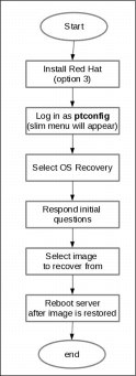
Figure A-5 OS Recovery sequence
The steps shown in Figure A-5 are mostly actions that are composed of automated procedures that require minimal human intervention. However there is one action that requires basic knowledge of the cluster layout on which the recovery is being performed. This action is represented by the Respond initial questions box in the flowchart.
The initial questions are displayed when the OS Recovery menu option is selected, as shown in Example A-3. The initial questions are used to allow the OS Recovery process to properly determine which node is being recovered which in turn is required to be able to display the appropriate OS image files in case this is a dual node cluster. For this reason, the person that is doing the recovery must be aware of the cluster configuration and also the location of the node (upper slot or lower slot) that is being recovered in order to increase the possibilities of recovering the system.
Example A-3 OS Recovery Initial questions
++++++ Starting OS Image Recovery ++++++
Is this a dual node cluster? [Y/N]
N <---- User response
Obtaining canister index
Canister 2 will be recovered
Is this correct? [Y/N]
Y <---- User response
|
Note: Failing to properly define the node that is being recovered can result in duplicated configurations including duplicated IP addresses and duplicated WWNs, which in turn can cause more problems.
|
When the OS Recovery process displays the available images, it will also include a time stamp for each of them. The time stamp can be used to determine the most suitable image to recover from (for example, the most recent image might have better chances of containing the most recent version of the installation and configuration files).
Every image that is successfully created is marked with a special file, which indicates that It contains all the files it was supposed to contain. In other words, It indicates that the image is complete and valid.
A validation of the selected image is performed by the OS Recovery process. If this special file is not detected, you are warned that the image might not be complete; however, you are given the option to proceed with the recovery.
|
Important: Do not proceed with the restoration of an incomplete image unless indicated by IBM support.
|
OS Recovery was designed to reduce the recovery time when a node reinstallation is needed, however the previous Node Replacement procedure (that is selected through the Recover Configuration for a replaced server option) is available also.
The difference between OS Recovery and Node Replacement is as follows:
•OS Recovery stores the installation and configuration files in an image file that resides in one of the front SAS disks in a DD6.
•Node Replacement rebuilds the configuration of a ProtecTIER server by reading the configuration stored in the repository of the system.
Another difference between both processes is that in order to execute Node Replacement on a node, the node must be upgraded to the same level of code as the repository which could imply to perform more than one code upgrade after the initial installation before executing the Replacement.
Online fsck command
This section describes a method to run the File System Check (fsck) command while backups are being sent to the ProtecTIER system.
|
Important: The fsck command must be run under the guidance of IBM support and should never be attempted without a deep analysis of the situation present in the system.
|
The Linux fsck tool
In Linux, everything that is managed by the operating system is represented by a file. To be able to manage such files, a file system must exist. One of the main functions of a file system is to enable read/write access to the files it contains. In addition, some file systems include security features and other more advanced characteristics that make them unique.
Most Linux file systems include a special set of tools that are used to attempt and repair inconsistencies that can potentially damage the files they contain. These tools are called system-specific checkers. What fsck does is simply call the appropriate checker according to the type of file system that is being analyzed or repaired.
Execution of fsck
Various situations might require the running the fsck command, and many of those situations are potential data-loss scenarios that must be treated carefully. In general, to try to repair a file system using fsck, the system must be unmounted, which implies that the access to the files it contains is suspended.
Although this is also true for a ProtecTIER system, it has major implications because the ProtecTIER repository is built on top of a Linux file system. Losing access to any of the components of the repository can cause adverse situations, such as from losing access to a subset of the user data, to being unable to send new backups and restoring the existing ones.
Running fsck consumes a large amount of RAM and, depending on the size of the file system, it can potentially allocate nearly 100% of the memory in the system. This allocation puts extra stress on the system were it is running, especially when other applications are also requesting RAM to operate. For this reason, the general suggestion when running fsck, traditionally, as shown in Example A-4, is to first close all other programs and then let the check run for as long as needed.
Example A-4 Traditional fsck execution
fsck -y -v /dev/mapper/vgfs0002-lvfs0002
This way of course translates into long outages in ProtecTIER systems during which no backups or restores will work.
Online fsck procedure
To reduce down time and to allow the continuation of backup and restore activities, starting with ProtecTIER code version 3.3.7, a method to run fsck without losing access to the data was developed.
|
Important: The following requirements must be met in order to run the online fsck command:
•ProtecTIER must be configured as a two-node cluster.
•Each ProtecTIER node must be configured with at least 64 GB of RAM.
One of the following criteria must be true in order to have access to the data:
•Medium changer is active on the node that is up during fsck execution.
•Control Path Failover (CPF) is enabled if you use IBM Spectrum Protect (formerly Tivoli Storage Manager) as backup application.
|
The procedure is as follows:
1. Select one of the ProtecTIER nodes.
2. At the login prompt, log in with the ID root and the password admin.
3. Shut down the vtfd and the ptcluster service in the following order:
#service vtfd shutdown
#service ptcluster shutdown
#service ptcluster shutdown
4. Start the cman and clvmd services in the following order:
#service cman start
#service clvmd start
#service clvmd start
5. For each of the problematic File Systems, run the gfs_fsck -yv command in the background and with high verbosity. Direct the output to a file as shown in Example A-5.
Example A-5 The fsck command run in the background with high verbosity
#fsck -yv logical_volume_name > /pt_work/logical_volume_name_fsck.out 2>&1 &
|
Note: ProtecTIER supports up to 10 parallel fsck instances.
|
6. When all the fsck processes are complete, collect the generated output files and make them available for IBM support to analyze. IBM support should indicate what the next steps are to regain access to the affected File Systems based on the analysis of the output files.
Dedup estimator tool
The dedup estimator tool can help you analyze the effect of deduplication on the data that is stored in the back-end disk arrays. The functions described in this section are an alternative to the analyze_session tool, which is limited to the data that currently resides in the repository. This new method can help determine possible corrective actions to improve the factoring ratio of the data, such as redirecting dedup unfriendly data to other backup targets or more complex actions designed with help of IBM support when possible.
Previous solution
The dedup estimator tool was introduced in the ProtecTIER v3.3.7 code package. Before that version, the ProtecTIER solution included only one tool to process the deduplication statistics to create user-readable reports. This analyze_sessions tool is still supported in ProtecTIER v3.4 code package. The tool can analyze the deduplication information of the data ingested by ProtecTIER and generates a report that groups this information by session, day, hour, and month. However, it does not account for data that expired or that was deleted from the repository. At a low level, this tool works by analyzing the Compressor Logs that are stored in the repository.
Tool functions
The dedup estimator tool runs concurrently and has no effect in the overall performance of the system when executed, even when the list of barcodes to analyze is large.
The interface of the tool is accessed through the ProtecTIER command-line interface (ptcli), which means that in order to call it, a valid user profile must exist. If no profile exists or if you want create a new one, complete these steps:
1. Run the following command:
/opt/dtc/ptcli/ptcli -p [file name with full path]
2. When asked, enter a valid user name and password.
|
Note: The user name and password must be previously defined in the ProtecTIER Manager GUI.
|
In general, when a valid profile already exists, the ptcli tool has the following syntax:
/opt/dtc/ptcli/ptcli [command name] --loginFile [path to the profile file] [command specific options]
Function: CalculateVtlDedupRatioByFile
This function calculates the VTL deduplication ratio for a list of cartridges defined in a plain text file.
The syntax is as follows:
/opt/dtc/ptcli/ptcli CalculateVtlDedupRatioByFile --loginFile /tmp/myProfile --file PATH
In this syntax, the PATH argument contains the full path to the location of the list of cartridges or barcodes to be analyzed. The input file must be a plain text file with one barcode per line, as in the following example:
A00001
A00002
A00003
The CalculateVtlDedupRatioByFile function has the following optional parameters:
•[--maxErrorsPercentage NUM]
NUM indicates the maximum errors percentage in the range of 0 - 100. The default value is taken from the GetDedupRatioParameters function output.
•[--tolerancePercentage NUM]
NUM indicates the tolerance percentage in the range of 0 - 100. The default value is taken from the GetDedupRatioParameters function output.
•[--numOfSamples NUM]
NUM indicates the number of samples used to generate the analysis. The default value is taken from the GetDedupRatioParameters function output.
Function: CalculateVtlDedupRatioByLibrary
This function calculates the VTL deduplication ratio by library.
The syntax is as follows:
/opt/dtc/ptcli/ptcli CalculateVtlDedupRatioByLibrary --loginFile /tmp/myProfile --libraryName LIBRARY
In this syntax, the LIBRARY argument contains the name of the library to be analyzed. All the cartridges residing in the library will be used to generate the final report.
The CalculateVtlDedupRatioByLibrary function has the following optional parameters:
•[--maxErrorsPercentage NUM]
NUM indicates the maximum errors percentage in the range of 0 - 100. The default value is taken from GetDedupRatioParameters function output.
•[--tolerancePercentage NUM]
NUM indicates the tolerance percentage in the range of 0 - 100. The default value is taken from GetDedupRatioParameters function output.
•[--numOfSamples NUM]
NUM indicates the number of samples used to generate the analysis. The default value is taken from GetDedupRatioParameters function output.
Function: CalculateVtlDedupRatioByRange
This function calculates the VTL deduplication ratio for a range of cartridges specified in the parameters.
The syntax is as follows:
/opt/dtc/ptcli/ptcli CalculateVtlDedupRatioByLibrary --loginFile /tmp/myProfile --fromBarcode BARCODEFROM --toBarcode BARCODETO
In this syntax, the BARCODEFROM argument contains the initial barcode of the range and BARCODETO contains the last barcode of the range.
This function has the following optional parameters:
•[--maxErrorsPercentage NUM]
NUM indicates the maximum errors percentage in the range of 0 - 100. The default value is taken from GetDedupRatioParameters function output.
•[--tolerancePercentage NUM]
NUM indicates the tolerance percentage in the range of 0 - 100. The default value is taken from GetDedupRatioParameters function output.
•[--numOfSamples NUM]
NUM indicates the number of samples used to generate the analysis. The default value is taken from GetDedupRatioParameters function output.
Sample output of the functions
Example A-6 shows output of using one of the dedup estimator functions.
Example A-6 Output from a dedup estimator function
Result:
#### WARNING!! ####
All open sessions of PT Manager must be terminated before running Dedup Estimator utility.
To continue working with PT Manager while running the Dedup Estimator utility, connect to PT Manager as ptoper.
Please wait while Dedup Estimator is working. This may take a few minutes to complete.
Preparing: 100% completed
Analyzing: 100% completed
Calculating: 100% completed
Node-id = 1
Estimated compression-ratio = 1:2.09
Estimated dedup-ratio = 1:3.61
Estimated overall factoring-ratio = 1:7.54
16384 successful samples out of 16384
Local directory cloning for FSI
This section describes a procedure to clone a local directory to create semi-instantaneous clones of directories in ProtecTIER FSI repositories at the source site in a replication environment.
|
Notes:
•This procedure works equally well if the repository is not in a replication environment.
•ProtecTIER GA Version 3.4 was released with only the Virtual Tape Library (VTL) interface support. File System Interface (FSI) support was added to ProtecTIER PGA 3.4 Version. For details, see the announcement letter:
|
This feature is similar to the procedure for cloning an FSI replication destination directory described in 22.4.2, “ProtecTIER FSI cloning” on page 403. However subtle differences between both procedures exists.
Consider the following information about the procedure for cloning a local directory for FSI:
•This procedure is intended to be run at the source site.
•This procedure cannot be run from the ProtecTIER Manager GUI, only from the command line.
•The main objective of this procedure is not to test a DR scenario but to create snapshots of directories in a specific point in time
Cloning a local directory in FSI
To clone a local directory in FSI, the command shown in Example A-7 must be issued from a command line on the ProtecTIER node that is attached to the repository where the FSI directory resides.
Example A-7 Cloning a local directory using ptcli
/opt/dtc/ptcli/ptcli CloneDirectory --loginInline [user,password] --force --sourceFS [SOURCEFS] --targetFS [TARGETFS] --sourceDir [SOURCEDIR] --targetDir [TARGETDIR]
The following list describes the parameters used in Example A-7:
•user,password
A valid user and password with administrator privileges is required. For the PT Manager GUI, ptadmin,ptadmin are the default credentials.
•SOURCEFS
The name of the file system where the directory that will e cloned resides, as seen in the PT Manager GUI.
•TARGETFS
The name of the file system where the clone of the directory will reside. TARGETFS can be the same as SOURCEFS.
•SOURCEDIR
The full path to the directory that will be cloned as seen in the PT Manager GUI. If the directory is under root, then use only its name without the initial forward slash (/) character. If it is a sub-directory, continue forming the path by following the UNIX file path format.
•TARGETDIR
The full path to the new directory created after cloning the SOURCEDIR. If the new directory will be under root, then use only the name of the new directory without the forward slash (/) character. It it will be a sub-directory, then continue forming the full path by following the UNIX file path format.
After a local directory is cloned, the new directory will have read/write permissions and the local repository can use it as if it was any other directory residing in the local repository. The local repository can even create a CIFS share or an NFS export on top of a cloned directory without issues.
Local directory cloning benefits
Cloning the local directory for FSI provides the following benefits when applied in conjunction with a certain backup application such as IBM Spectrum Protect or Veritas NetBackup, or during a specific situation:
•A local directory can be duplicated to a new directory without any impact on the physical used space because the cloned directories have a change rate of 0% or, in other words, they are 100% deduplicated.
•Data restoration from a specific point in time can be implemented for deleted data.
•Local directory cloning can be used in test environments to restore data.
•Local directory cloning can be used together with a backup application to resolve issues related to incremental and full backups.
|
Note: To demonstrate this point, we use RMAN backups as an example. Normally a full backup is run followed by several incremental backups the next days. The problem is that when you apply the incremental backup to a full backup, the original full backup is lost and replaced by the merged version of the full plus the incremental backups.
To resolve this issue, create a clone of the full backup prior to an incremental update operation, which will not consume physical space in the repository. In this way, you can generate backups in fractions of time. In other words, instead of generating only one full backup and many incrementals, you can now have one full plus one incremental backup every day which will accelerate the restores in case they are needed.
|
Commands to send files to and receive files from IBM Support
This section includes a set of commands that can be used to upload or download files when you interact with the Enhanced Customer Data Repository (ECUREP). This repository is used by IBM support to receive files, such as ProtecTIER Service Reports, to diagnose problems in the system. It is also used to send large files to the client when needed. Such files can include ProtecTIER software packages, repaired ProtecTIER repository structures and other files that can not be attached to a regular email.
|
Note: If you are concerned about specific aspects of the ECUREP security standards, contact your sales representative to ask about the Blue Diamond program and how it can be applied to secure your data.
|
Commands to upload files from a ProtecTIER node to ECUREP
One of the most common tasks related to the support process is to upload a service report. This report contains all the necessary files and logs for IBM to start working on an analysis related to a support case.
Several ways are available to upload a service report to ECUREP and attach it to a problem management record (PMR). The method described here aims to reduce the total time needed to make the Service Report available in a PMR by minimizing the number of file transfers needed. Depending on the type of service report and depending on specific conditions present in the ProtecTIER node when the file is created, the final size can vary from hundreds of megabytes to several gigabytes, and this can be problematic when trying to upload it to ECUREP.
Prerequisite
The only real prerequisite is to make sure the ProtecTIER node where this procedure is being executed has access to the Internet. One way to test this access is to try to ping known IP addresses and to try to directly connect to ECUREP.
|
Note: The configuration of Red Hat in ProtecTIER does not include capabilities to resolve domain names. In other words, all the tests and the commands to transfer the files must be executed by using the IP addresses associated with the services that are being accessed.
|
Complete the following steps:
1. Make sure the system is authenticated on all the firewalls that control the access to the Internet. One way to do this is to use Telnet to connect to a known DNS as many times as needed until Telnet does not return with a prompt. Example A-8 shows how this task is performed. In this case, Telnet was able to connect, which means that a firewall is requesting authentication. The DNS used here does not respond to the Telnet protocol so one way to confirm that all the necessary firewalls were passed is by making sure Telnet does not connect successfully to this IP address.
Example A-8 Telnet to a known DNS
[root@donramon ~]# telnet 8.8.8.8
Trying 8.8.8.8...
Connected to 8.8.8.8 (8.8.8.8).
Escape character is '^]'.
2. Try to connect through FTP to one of the ECUREP IP addresses. The IP address used in Example A-8 might vary depending on how the fully qualified domain name is resolved.
Example A-9 shows the results of a successful attempt to ensure that the system is authenticated on all firewalls that control access to the Internet.
Example A-9 FTP connect to ECUREP IP address
[root@vela ~]# ftp 192.109.81.7
Connected to 192.109.81.7.
220-FTP Server (user '[email protected]')
220
500-Syntax error -- unknown command
500
500-Syntax error -- unknown command
500
KERBEROS_V4 rejected as an authentication type
Name (192.109.81.7:root):
3. If the FTP connection is successful, then this ProtecTIER node is able to connect to ECUREP. The next step is to prepare the service report or any other file that should be attached to a PMR for the transfer. This preparation implies renaming the file to add the number of the PMR at the beginning of the file name to allow ECUREP to move it to the appropriate path associated with the PMR. Example A-10 describes how to do this task.
Example A-10 Naming convention for files sent to ECUREP
If the file is a service report, it is very possible it will be located under /pt work directory, similar to this:
/pt_work/ProtecTier__vela_default_Mar_6_2016_0_57_49_Report.tar
If the target PMR is for example 12345,000,123 then the file should be renamed as follows:
mv ProtecTier__vela_default_Mar_6_2016_0_57_49_Report.tar 12345,000,123_ProtecTier__vela_default_Mar_6_2016_0_57_49_Report.tar
4. Finally, the file can be transferred to ECUREP by issuing the command in Example A-11. Be sure to notice that the file will take some minutes to be listed in the directory in the PMR because it is automatically moved by a process running in the background in the ECUREP repository.
Example A-11 Command to initiate the transfer of a file from the PT node to ECUREP
curl -u anonymous:[EMAIL] -T 12345,000,123_ProtecTier__vela_default_Mar_6_2016_0_57_49_Report.tar ftp://192.109.81.7/toibm/aix/12345,000,123_ProtecTier__vela_default_Mar_6_2016_0_57_49_Report.tar
Consider the following information about Example A-11:
– anonymous indicates that the file is being uploaded anonymously.
– [EMAIL] is a valid client email address.
– 192.109.81.7 is the IP address of ECUREP.
– /toibm/aix/ is a directory in ECUREP repository to receive files sent by customers.
Receiving files from IBM support
The ECUREP security rules have evolved over time to become more reliable. Derived from these improved security policies, the old practice that involved placing files in a specific ECUREP directory for a client to download anonymously was deprecated.
Currently, the only official procedure for IBM to send a file to a client is by making an explicit request in ECUREP to place it in a public FTP server for a limited period of time. After the request is submitted, the client will receive an email reply. A link to download the file directly will be included in that same email.
This way implies that only files associated with PMRs can be transferred from ECUREP to a client. This limits the number of users that can perform this operation. Only support engineers, technical advisors, technical advocates and people with special permissions will be able to do it.
|
Note: For additional information about sending or receiving files through the ECUREP service, contact IBM Support.
|
Graphical performance tool
Starting in ProtecTIER code 3.4, a new tool was added to the base installation of the ProtecTIER. The tool allows the creation of graphical reports based on the processing of the statistical data collected by each ProtecTIER system.
The tool generates an HTML page that can be opened in any web browser. After it is created, the report must be transferred to a work station because the ProtecTIER code package does not include programs to open such files.
This tool generates several graphs that can be used to visualize and detect problems that are related to low performance, bottle necks, high-delete backlog, high-fragmented space, and others related to replication activities.
For more details about this tool, see the topic about creating a performance analysis report in IBM TS7650 with ProtecTIER V3.4 User's Guide for VTL Systems, GA32-0922-10.
ProtecTIER licensing tips
This section contains tips regarding to the capacity licensing of ProtecTIER. The information described here was gathered from the most common questions that are associated with implementation of a ProtecTIER system.
For more information, contact your IBM sales representative.
Capacity representation in the ProtecTIER Manager GUI
The ProtecTIER Manager GUI displays capacity information in the following format:
•A tebibyte (TiB) is defined as a multiple of the byte data unit. More specifically, 1 TiB equals 240 bytes or 1024 gibibytes (GiB), which equals 1 099 511 627 776 bytes.
•A terabyte (TB) in contrast, is defined as 1012 bytes, which equals 1 000 000 000 000 bytes.
Both units of measurement are usually used as synonyms; however, knowing the exact values of both scales is important. It explains why 1TB is approximately 1.1 TiB and it also explains the numbers displayed by the ProtecTIER Manager GUI.
Figure A-6 shows an example of capacity representation in the ProtecTIER Manager GUI.

Figure A-6 Capacity view in the ProtecTIER Manager GUI
Figure A-6 on page 454 shows how the capacity is represented in the ProtecTIER Manager GUI. The highlighted numbers in the figure represent the following information:
1. Usable capacity: Licensed capacity reduced by the Linux file system overhead and other ProtecTIER internal overhead. It is displayed as a binary value (GiB or TiB).
2. Configured real licensed capacity: The licensed real capacity, which is the sum of all user data file systems allocated to the repository.
3. Configured licensed capacity: This value represents the capacity that was configured when the repository was created. This number indicates how much capacity the current metadata is able to manage. This number can be larger than the value displayed (highlighted item 2) because ProtecTIER allows preconfiguration of the metadata to leave it ready for future capacity increases.
The role of the metadata space in the licensing process
The capacity license of ProtecTIER considers only the user data portion of the repository. The user data portion is where the actual deduplicated data is stored in the storage system that provisions the LUNs that are presented to the ProtecTIER system.
The metadata space required by the ProtecTIER repository stores vital structures that are used by all the ProtecTIER internal modules to operate. Its size depends on characteristics of the repository that is being created, such as maximum throughput, expected factoring ratio, and the type and configuration (RAID configuration) of the disks that are allocated for metadata.
Reconfigure an IBM Spectrum Protect instance attached to ProtecTIER after a reboot
This section describes a procedure to recover the configuration of an IBM Spectrum Protect (formerly Tivoli Storage Manager) instance when it is attached to a ProtecTIER system. The procedure described in this section is valid for IBM Spectrum Protect instances running on Linux.
When ProtecTIER services are restarted or when the ProtecTIER server is rebooted, the serial numbers of the tape devices might differ from those that IBM Spectrum Protect is expecting to detect. To resolve this issue, the following procedure can be applied:
1. Create a file named 98-lin_tape.rules in the /etc/udev/rules.d/ directory.
The contents of the file are shown in Example A-12.
Example A-12 Contents of the 98-lin_tape.rules file
KERNEL==”IBMtape*n”,ATTR{serial_num}==”8515844000”,SYMLINK=”lin_tape/by-id/IBMtape7n”
.....
KERNEL==”IBMtape*n”,ATTR{serial_num}==”8515844029”,SYMLINK=”lin_tape/by-id/IBMtape29n”
2. You can query ATTR{serial_num} by issuing the following command:
udevadm info --attribute-walk --name /dev/IBMtapeX
Example A-13 How to change persistent_n_device parameter
#lin_taped stop
#modprobe -r lin_tape
#vi /etc/modprobe.d/lin_tape.conf
options lin_tape persistent_n_device=1
* save and exit
#modprobe lin_tape
#lin_taped
#ls -l /dev/lin_tape/by_id/
* one or more files should be created in the ../lin_tape/by_id/ path
4. Create a library in IBM Spectrum Protect and use IBMtape*n.
..................Content has been hidden....................
You can't read the all page of ebook, please click here login for view all page.