

Maintenance and upgrades
This chapter describes the available maintenance and upgrades and includes the following sections:
9.1 Operations Administrator user category
IBM Spectrum Accelerate introduces an Operations Administrator user category. A user who is assigned to this category can complete repair tasks for physical components and has some of the abilities that often are held by IBM Support users.
The Operations Administrator user category is used for system maintenance operations, and the Storage Administrator user category is used for storage management operations. Table 9-1 lists the functions that are assigned to the new Operations Administrator user category as compared to the Storage Administrator user category.
Table 9-1 Functions assigned to Storage Administrator and Operations Administrator user category
|
System Operations
|
Storage Administrator
|
Operations Administrator
|
|
Pool, volume, and snapshot management
|
X
|
|
|
Migration and replication
|
X
|
|
|
User and group management
|
X
|
|
|
Host definition and connectivity
|
X
|
|
|
Define iSCSI connectivity
|
X
|
X
|
|
Deploy and upgrade IBM Spectrum Accelerate system
|
X
|
X
|
|
Upgrade IBM Spectrum Accelerate system
|
X
|
X
|
|
Add new modules to system
|
|
X
|
|
Replacement for modules and hard disks
|
|
X
|
|
Resolving service flags
|
|
X
|
9.2 Concurrent IBM Spectrum Accelerate system upgrade
IBM Spectrum Accelerate systems can be concurrently upgraded by using the IBM XIV Management GUI. These upgrades bring fixes and features to systems that are deployed within an organization.
The following prerequisites must be met to successfully complete the concurrent upgrade process:
•A user that is assigned to the Operation Administrator or Storage Administrator user category on the IBM Spectrum Accelerate system that is being upgraded.
•A valid IBM Spectrum Accelerate upgrade package.
•The IBM XIV Management Tools version 4.8.0.4 or later.
Complete the following steps to concurrently upgrade IBM Spectrum Accelerate system by using the IBM XIV Management GUI:
1. Obtain the system upgrade package for the IBM Spectrum Accelerate system from IBM Passport Advantage. For more information about accessing IBM Passport Advantage, contact an IBM sales representative.
|
Note: The IBM Spectrum Accelerate update package is made available in a compressed file from IBM Passport Advantage. Within the compressed file is the actual upgrade package, which has an extension of tar.gz.
Extract and place the upgrade package tar.gz file on the Windows workstation that is used to complete the upgrade.
|
2. Connect to the Spectrum Accelerate system with a user that is a member of the Storage Administrator category by using the IBM XIV Management GUI. Select the IBM Spectrum Accelerate system from the All Systems view.
3. Select Systems → System Settings → Upgrade to begin the system upgrade process, as shown in Figure 9-1.

Figure 9-1 Opening the IBM Spectrum Accelerate system upgrade wizard
4. Select the upgrade package in the Choose an upgrade file window and select Open, as seen in Figure 9-2.

Figure 9-2 Selecting the upgrade package
|
Note: Ensure that the tar.gz upgrade package is selected and not the archive, which was downloaded from IBM Passport Advantage.
|
5. Verify that the system can be upgraded by using the upgrade package and that no system components are in a faulty state.
When a valid system upgrade package is chosen, a validation prompt is displayed (see Figure 9-3) that requests approval to proceed with the upgrade. Select OK to apply the upgrade. If you are unsure about completing the upgrade, select Cancel.

Figure 9-3 Proceed with IBM Spectrum Accelerate system upgrade
6. The upgrade process proceeds through several operations. Each operation is completed sequentially and is displayed as a complete percentage in the IBM XIV Management GUI.
The progress indicator bar provides information for each operation of the upgrades. These upgrade operations include validating the upgrade file, uploading the upgrade to the IBM Spectrum Accelerate system, preparing the system to apply the upgrade, and applying the upgrade to the system.
This process can take time and is dependant upon the number of modules and network bandwidth between the upgrade workstation and the IBM Spectrum Accelerate system. Examples of progress indicators for each operation are shown Figure 9-4.

Figure 9-4 IBM Spectrum Accelerate system upgrade progress
7. When the upgrade process completes, a window opens (see Figure 9-5) that indicates that the upgrade completed successfully. Click OK to complete the upgrade process.

Figure 9-5 Message indicating successful completion of the system upgrade
8. Verify that the IBM Spectrum Accelerate system was successfully upgraded by clicking Systems → System Settings → System, as shown in Figure 9-6.

Figure 9-6 Opening the System settings window to verify upgrade
9. In the General tab, verify that the System Version field shows the correct IBM Spectrum Accelerate system software version, which is consistent with the upgrade. An example of an updated system version is shown in Figure 9-7 on page 238.
After the upgrade completes, all events from the upgrade process are available within the Event view. Select System → Events from the System view to browse to the Event view.

Figure 9-7 Verifying that the system version now reflects the update
9.3 Adding a module to an IBM Spectrum Accelerate
IBM Spectrum Accelerate allows for systems to be deployed by using as few as three modules. As more capacity is required, VMware ESXi servers can be provisioned and deployed as extra modules until the system reaches its maximum capacity of 15 modules. This capability allows the system to easily scale to meet increasing workload requirements.
The following prerequisites must be met to successfully add modules to the system:
•A user that is assigned to the Operation Administrator category on the IBM Spectrum Accelerate system.
•Administrative user access to the VMware ESXi server by using the VMware vSphere Client.
•Extra VMware ESXi servers that contain the same number of hard disk drives (HDDs) and solid-state disks (SDDs) at the same capacity as is already in the system to which it is being added.
•IBM Spectrum Accelerate deployment kit that contains an equal or earlier code version than what is installed on the system.
•The IBM Spectrum Accelerate deployment configuration XML file that was used during initial deployment of the system.
•XIV management tools v4.7 or later for Spectrum Accelerate version 11.5.1 or 11.5.3. Deployment Kit Web UI or command line for Spectrum Accelerate version 11.5.4. For more details refer to Spectrum Accelerate 11.5.4 User Guide.
9.3.1 Adding a module by using the XIV GUI and VMware vSphere client
To add a module for v11.5.1 or v11.5.3 by using the IBM XIV Management GUI and VMware vSphere client, complete the following steps:
1. Prepare the deployment workstation by acquiring the IBM Spectrum Accelerate deployment package. Complete the following steps:
a. Obtain an IBM XIV Management GUI deployment package that is at the same or earlier code version as what is on the IBM Spectrum Accelerate system.
|
Note: Modules cannot be added to a system that uses a newer version of the IBM Spectrum Accelerate system software than what is already in use on the IBM Spectrum Accelerate system.
|
b. Extract the deployment kit to a folder on the workstation that is used to complete the module deployment by using the IBM XIV Management GUI.
2. Prepare a new VMware ESXi server for use as a new IBM Spectrum Accelerate module. Complete the following steps:
a. Obtain and provision an VMware ESXi server that contains the same number of HDDs SSDs, and minimum memory as is being used within the IBM Spectrum Accelerate system.
b. Set up and configure the VMware ESXi server software on the module. For more information, see 4.2, “Preparing the Windows Workstation” on page 56.
c. Ensure that the data store and network port groups follow the naming conventions that are used by the IBM Spectrum Accelerate system and that the deployment configuration XML file was modified to use the correct resource names.
d. Ensure that the VMware ESXi server has SSH access enabled.
|
Important: The new VMware server must be configured to use the same vSwitch network names and be accessible on the same subnets as the IBM Spectrum Accelerate system.
|
3. Complete the following steps to use the IBM XIV Management GUI to begin adding modules:
a. Connect to the IBM Spectrum Accelerate system by using the IBM XIV Management GUI with a user that is a member of the Operations Administrator user category.
b. Browse to the IBM Spectrum Accelerate system, which is expanded from the All Systems view. Select Define New Module from the menu bar, as shown in Figure 9-8.

Figure 9-8 Defining a new module IBM XIV Management GUI
4. Complete the required fields within the Deploy New Module window.
In the General tab, select the Deployment Executable File that is in the deployment kit that was extracted on the workstation. Import the Spectrum Accelerate system deployment configuration XML file that was generated during the initial deployment of the system. For more information, see 4.3, “Deployment by using the IBM XIV Management GUI” on page 58.
An example of a fully populated General tab is shown in Figure 9-9.
|
Tip: The use of a deployment configuration XML file populates the configuration into the new module deployment utility and helps prevent errors.
|

Figure 9-9 Deploy New Module tool General tab
5. Complete the required fields in the System Settings tab, as shown in Figure 9-10.

Figure 9-10 Spectrum Accelerate system settings entered or imported
Complete the following steps:
a. Select the System Settings tab and verify that the system configuration was properly loaded from the deployment configuration XML file.
b. If the original deployment configuration XML file is not available, enter the system information for the system, including Name, IBM Customer Number, Management Gateway, Management Netmask, Interconnect MTU, Off-Premise Setting, and Run Diagnostics.
This information can be gathered from the system by using the IBM XIV Management GUI and the deployment records.
6. Complete the required fields on the vCenter Settings tab, as shown in Figure 9-11.

Figure 9-11 vCenter Settings configuration for Spectrum Accelerate system not using vCenter
Complete the following steps:
a. Select the vCenter Settings tab and verify that the system configuration was properly loaded from the deployment configuration XML file.
b. If the original deployment configuration XML file is not available, enter the system information for the vCenter Server Settings, which includes the vCenter server IP/Hostname, vCenter administrative user name, vCenter administrative user password, and data center.
7. Complete the required fields in the Module Settings tab, as shown in Figure 9-12.

Figure 9-12 Module settings tab with IBM Spectrum Accelerate system information
Complete the following steps:
a. Select the Module Settings tab and verify that the Memory, Number of Disks, Number of SSDs, Virtual Disks settings, and individual module settings were accurately imported from the deployment configuration XML file.
b. If the original deployment configuration XML file is not available, enter the system information for the Module Settings, which includes the CPU Cores, Memory, Number of Disks, Number of SSDs, and individual module settings.
8. Complete the required fields in the Add Module wizard, as shown in Figure 9-13.

Figure 9-13 Add Module window for individual modules
Complete the following steps:
a. Select Green Plus to add the new module and open the Add Module wizard. If a deployment configuration XML file was used, most of the module configuration is completed with incremented values.
b. If the original deployment configuration XML file is not available, enter the module information, which includes the following values:
• Data store name
• Management TCP/IP address
• VMware ESXi server TCP/IP address
• VMware ESXi administrative user name
• VMware ESXi administrative password
• Network port group names
• Interconnect TCP/IP address
• Interconnect subnet
All fields must be populated before the new module can be deployed.
c. After the settings are entered, select Add to add the module to the systems configuration.
9. Complete the following steps before the new IBM Spectrum Accelerate module is deployed:
a. Verify that the configuration fields are completed in all tabs of the Deploy New Module wizard.
|
Note: Before proceeding with the module deployment, export the configuration to preserve the new system configuration in case more modules are added in the future. Select Export Current Configuration from the General tab to save the deployment configuration XML file.
|
b. Select Deploy Module. The module deployment process completes after all modules successfully receive the IBM Spectrum Accelerate system software and are brought online.
c. When the new module is deployed, it must complete a tested component to ensure compliancy with the system configuration. Right-click the module within the System view and select Test.
d. When the testing process completes, the module must be phased into the system so that the IBM Spectrum Accelerate system can begin to use it. Right-click the module and select Phase in to being the phase in process. The system enters a redistribution state as the data is rebalanced across the new modules.
|
Note: The redistribution process is run in the background and completes after all the data on the system is redistributed to account for the new modules. The amount of time it takes to complete the redistribution process can be many hours and depends on the amount of data, number of modules and disks, and the interconnect bandwidth of the system.
|
9.3.2 Adding a module by using the XCLI and VMware vSphere client
To add a module by using the XCLI and VMware vSphere client, complete the following steps:
1. Obtain an IBM Spectrum Accelerate command-line deployment package with a code version level that is equal to, or lower than, what is installed on the IBM Spectrum Accelerate system.
|
Note: Modules cannot be added to a system if the modules have a newer IBM Spectrum Accelerate system software version than what is installed on the IBM Spectrum Accelerate system.
|
2. Complete the following steps to prepare a new VMware ESXi server for use as a new IBM Spectrum Accelerate module:
a. Obtain and provision an VMware ESXi server that contains the same number of HDDs, SSDs, and minimum memory as is used within the IBM Spectrum Accelerate system.
b. Set up and configure the VMware ESXi server software on the module. For more information, see 4.2, “Preparing the Windows Workstation” on page 56.
c. Ensure that the data store and network port groups follow the naming conventions that are used by the IBM Spectrum Accelerate system. Also, ensure that the deployment configuration XML file was modified to use the correct resource names.
d. Ensure that the VMware ESXi server has SSH access enabled.
|
Note: The VMware ESXi server must be configured to use the same vSwitch network names. The server also must be accessible on the same subnets and virtual LAN networks as the IBM Spectrum Accelerate system.
|
3. Complete the following steps to prepare the Linux deployment workstation:
a. Place the IBM Spectrum Accelerate command-line deployment package on the deployment Linux workstation and open a command-line session.
b. Place the IBM Spectrum Accelerate deployment configuration XML file in a folder that the user account completing the deployment process has privileges.
4. The IBM Spectrum Accelerate system deployment configuration XML file must be prepared, as shown in Example 9-1. Modify the IBM Spectrum Accelerate deployment configuration XML file parameters so that they contain the system settings that were defined on the IBM Spectrum Accelerate system and VMware vCenter configuration if a vCenter is used.
The <esx_servers> section of the deployment configuration XML file contains the configuration for each module being added to the system.
All of the <esx_servers> stanzas must contain the module_id=”MODULE_#” field so that the IBM Spectrum Accelerate system can identify and assign the new modules in the proper module number.
Example 9-1 Adding a single fourth module to a system
<sds_machine
name="ITSO_SDS2"
interconnect_mtu="9000"
vm_gateway="192.168.121.1"
vm_netmask="255.255.255.0"
data_disks="11"
ssd_disks="0"
memory_gb="18"
off_premise="no"
icn="8811928">
<esx_servers>
<server
hostname="192.168.121.134"
username="root"
password="password"
Data store="MOD4_ds"
module_id="4"
mgmt_network="NETManagement"
interconnect_network="Interconnect_ISCSI"
iscsi_network="Interconnect_ISCSI"
vm_mgmt_ip_address="192.168.121.144"
interconnect_ip_address="14.115.10.23"
interconnect_ip_netmask="255.255.255.0">
</server>
</esx_servers>
</sds_machine>
|
Note: The VMware ESXi administrative user password can be changed after the system is successfully deployed. If more modules are added to the system or module maintenance must be completed, modify the deployment configuration XML file to reflect the new password.
|
5. Deploy the extra modules into the system, as shown in Example 9-2. Run the command-line deployment kit with the -a argument. This argument instructs the deployment kit to add modules to the system.
Example 9-2 shows the deployment kit being run with the options to add the module to the system by using the deployment configuration XML file.
|
Note: Example 9-2 also shows the deployment configuration XML file in the same folder as the deployment kit.
|
The deployment kit creates the IBM Spectrum Accelerate virtual machine on the VMware ESXi server and adds it to the IBM Spectrum Accelerate system.
|
Tip: The deployment process outputs any errors that are encountered during the deployment to the Linux command-line. Review this output to help diagnose failures that can occur during the deployment process.
|
Example 9-2 Running the deployment script
~$ ./xiv_sds_deployment_kit-latest.bash -a -c ITSO_SDS1_Module-4-Add.xml
|
Note: Ensure that the correct deployment configuration XML file is used and that it contains only the stanza for the modules that are being added. The use of an incorrect deployment configuration XML file can cause problems on a system up to and including potential data loss.
|
6. Connect to the IBM Spectrum Accelerate system by using the IBM XIV Management XCLI utility as a user who is a member of the Operations Administrator user category. The newly created module must be added to the IBM Spectrum Accelerate system configuration. Complete the following steps:
a. Run the module_equip command and provide the module_interconnect_ip= argument, as shown in Example 9-3.
Example 9-3 Equipping the added module
ITSO_SA1>> module_equip module_interconnect_ip=192.168.122.100
Details: Module has been added as Module-4
b. Verify that the module was added to the system by using the module_list command. The newly added module is displayed with the status failed and must be component tested and phased into the system that is to be used.
7. Use the IBM XIV Management XCLI utility with a user who is a member of the Operations Administrator user category to component test and phase in the newly added module. Complete the following steps:
a. Run the component_test component=1:Module:<MODULE_#> command to start a component test of the module. The testing process runs various checks to ensure that the module is compliant with the IBM Spectrum Accelerate system configuration. These tests can take some time.
b. Run the component_phasein component=1:Module:<Module_#> command to begin the phase in process. The system enters a redistribution status in which the system rebalances data to use the new module.
|
Note: The redistribution process is run in the background and completes after all the data on the system is redistributed to account for the new modules. The amount of time it takes to complete the redistribution process can span many hours and depends on the amount of data, number of modules and disks, and the interconnect bandwidth of the system.
|
9.3.3 Adding a module by using the Deployment Kit Web UI, Hyper-Scale Manager and VMware vSphere client
To add a module for v11.5.4 by using the IBM Hyper-Scale Manager and VMware vSphere client, complete the following steps:
1. Prepare the deployment workstation by acquiring the IBM Spectrum Accelerate deployment package. Complete the following steps:
a. Obtain an deployment package that is at the same or earlier code version as what is on the IBM Spectrum Accelerate system.
|
Note: Modules cannot be added to a system that uses a newer version of the IBM Spectrum Accelerate system software than what is already in use on the IBM Spectrum Accelerate system.
|
b. Extract the deployment kit to a folder on the workstation that is used to complete the module deployment.
2. Prepare a new VMware ESXi server for use as a new IBM Spectrum Accelerate module. Complete the following steps:
a. Obtain and provision an VMware ESXi server that contains the same number of HDDs SSDs, and minimum memory as is being used within the IBM Spectrum Accelerate system.
b. Set up and configure the VMware ESXi server software on the module. For more information, see 4.2, “Preparing the Windows Workstation” on page 56.
c. Ensure that the data store and network port groups follow the naming conventions that are used by the IBM Spectrum Accelerate system and that the deployment configuration XML file was modified to use the correct resource names.
d. Ensure that the VMware ESXi server has SSH access enabled.
|
Important: The new VMware server must be configured to use the same vSwitch network names and be accessible on the same subnets as the IBM Spectrum Accelerate system.
|
3. Complete the following steps to prepare the Windows deployment workstation:
a. Place the IBM Spectrum Accelerate command-line deployment package on the deployment workstation and open a PowerShell session.
b. Place the IBM Spectrum Accelerate deployment configuration XML file in a folder that the user account completing the deployment process has privileges.
4. Complete the following steps to deploy an IBM Spectrum Accelerate system by using the Deployment Kit Web UI:
a. To open the Deployment Kit Web UI, run the deployment script xiv_sds_deployment_win.cmd with the -w or --web-ui option, as shown in Example 9-4 and described in 3.3.3, “Deploying IBM Spectrum Accelerate from the Windows command line” on page 48. To open the Deployment Kit Web UI on Linux run the command as described in 3.4.3, “Deploying IBM Spectrum Accelerate from the Linux command line” on page 51.
Example 9-4 Open the Web UI
.xiv_sds_deployment_win.cmd -w

Figure 9-14 Web UI: Deploy new system
c. Open System Configuration as illustrated in Figure 9-15 on page 249 and enter all necessary information.

Figure 9-15 Web UI: System Configuration
d. Click + icon to add a new module as illustrated in Figure 9-16.

Figure 9-16 Web UI: Add Module
e. The module window contains the following specific configuration settings for an ESXi server:
General Settings:
• Module Number: Each extra module needs a number.
• Data store Name: This value defines the data store on the ESXi server on which the IBM Spectrum Accelerate system software is installed.
• Module Management IP: This value defines the IBM Spectrum Accelerate management TCP/IP address that is used to manage the system.
• ESXi Hostname / FQDN: This value defines the ESXi server management TCP/IP address or fully qualified domain name.
• ESXi Username: This value defines the user name of the administrative user on the ESXi server.
• ESXi Password: This value defines the password for the administrative user on the ESXi server.
• Confirm ESXi Password: This field provides confirmation that the supplied password was entered correctly.
Network Port Group Names:
• Interconnect: This value defines the port group name set on the ESXi server for the port group that is used as the interconnect network.
• ISCSI: This value defines the port group name set on the ESXi server for the port group that is used as the iSCSI host connectivity network.
• Management: This value defines the port group name set on the ESXi server for the port group that is used as the IBM Spectrum Accelerate management network.
Interconnect Settings:
• IP Address: This value defines the TCP/IP address that is used on the Interconnect port group setup on the ESXi server. This TCP/IP address must not conflict with only another TCP/IP address on the subnet.
• Netmask: This value defines the subnet netmask that is used to isolate the interconnect TCP/IPs on the subnet operate.
|
Note: The interconnect subnet exchanges data only between modules of the same IBM Spectrum Accelerate system. Therefore, there is no need for these TCP/IP addresses to be routable outside of their assigned subnet.
|
f. An example of a completed Add Module window is shown in Figure 9-17 on page 251.

Figure 9-17 Web UI: Add extra module
g. Select the Deploy System tab as depicted in Figure 9-18 on page 252. The following options are available:
• Skip VM Startup: Skips the startup of the IBM Spectrum Accelerate VMs.
• Only run the diagnostic phase: Checks if all prerequisites are fulfilled.
• Run only the ESXi verification step: Checks if the ESXi prerequisites are fulfilled.
• Configure ESXi parameters if needed: Gives the opportunity to configure ESXi parameters, if necessary.
• Log to syslog: Logs the deployment to syslog.
• Run the deployment serially: Run the deployment of one module after the other.
• Overwrite previous deployment: Deploys the configuration, even the IBM Spectrum Accelerate VMs were defined and running before. Use with caution, because it can destroy a running IBM Spectrum Accelerate system.
|
Note: Take care when the Overwrite previous deployment option is used because it deletes any virtual machines that feature the same name as the virtual machines that are defined in the deployment configuration.
|

Figure 9-18 Web UI: Deploy new module
h. The deployment of the new module starts as shown in Figure 9-19.

Figure 9-19 Web UI: Deploy new module start
5. Complete the following steps to equip the Spectrum Accelerate with the new module by using Hyper-Scale Manager (HSM):
a. Log in to https://<HSM-IP-address>:8443 with user role Storage Administrator or Operations Administrator. Select SYSTEMS & DOMAINS VIEWS → Systems as shown in Figure 9-20.

Figure 9-20 HSM: Systems

Figure 9-21 HSM: Select Equip Module
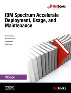
c. Enter Module Interconnect IP and click Apply as illustrated in Figure 9-22.
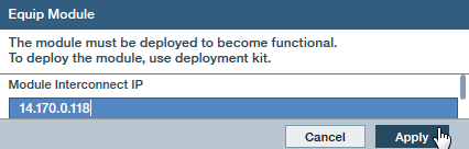
Figure 9-22 HSM: Equip Module

Figure 9-23 HSM: Monitor Hardware Health
e. Click the module as depicted in Figure 9-24.

Figure 9-24 HSM: Select Module

Figure 9-25 HSM: Select Phase In Component

Figure 9-26 HSM: Phase In Component
|
Note: The redistribution process is run in the background and completes after all the data on the system is redistributed to account for the new modules. The amount of time it takes to complete the redistribution process can be many hours and depends on the amount of data, number of modules and disks, and the interconnect bandwidth of the system.
|
9.4 Concurrent rolling hardware alterations to modules
There can be times when changes must be made to the underlying VMware ESXi servers that are running an IBM Spectrum Accelerate system. The cleanest method to complete these necessary changes to the VMware ESXi servers is to gracefully shut down the IBM Spectrum Accelerate system. However, gracefully shutting down the system is not always possible. In these instances, individual VMware ESXi server maintenance can be completed one at a time in a rolling fashion.
The following requirements must be met to successfully complete a rolling module upgrade:
•A user is assigned to the Operations Administrator category on the IBM Spectrum Accelerate system.
•Administrative user access to the VMware ESXi servers is available by using the VMware vSphere Client.
9.4.1 Concurrently removing single module for maintenance
To concurrently remove a module when the system is running, complete the following steps:
1. Verify that all components of the IBM Spectrum Accelerate system are in a good state by completing the following steps:
a. Connect to the IBM Spectrum Accelerate system by using the IBM XIV Management GUI with a user that is a member of the Operations Administrator user category.
b. Verify that there are no failed components by opening the IBM XIV Management GUI and browsing to the system component view, as shown in Figure 9-27. Verify that the status of all modules is OK.
|
Tip: If connected to the IBM Spectrum Accelerate system by using IBM XIV Management XCLI utility, run the component_list filter=notok command to verify component status.
If any components are in a failed state, resolve the issue before moving forward.
|

Figure 9-27 IBM XIV Management GUI showing all components in OK status
2. Start phasing out of the IBM Spectrum Accelerate module by using the IBM XIV Management GUI. Right-click the module that requires maintenance and select Phase out → Failed.
|
Note: The system enters redistribution (see Figure 9-28 on page 257) when the data that is on the module is migrated to other modules. This configuration provides data redundancy during the concurrent repair process.
The phase out process is run in the background and completes after all the data on the system is migrated to the other modules. The amount of time it takes to complete the phase out process can span many hours. This time depends on the amount of data, number of modules and disks, and the interconnect network bandwidth that is allocated to the system.
|

Figure 9-28 Manual phaseout started through the IBM XIV management GUI
3. Verify that the phase out of the module completed and power off the virtual machine by completing the following steps:
a. Verify that the phase out process completed by confirming that the bar in the lower right corner of the IBM XIV Management GUI features the label “full redundancy.”
b. Connect to the VMware ESXi server that is running the module virtual machine by using the VMware vSphere client with a user who has administrative privileges.
c. Turn off the IBM Spectrum Accelerate virtual machine by right-clicking the machine and selecting Power → Power Off, as shown in Figure 9-29.

Figure 9-29 Power menu for IBM Spectrum Accelerate virtual machine
d. A confirmation window opens in which the user is prompted for verification of the power off. Select Yes to complete the virtual machine shutdown process.
4. If hardware maintenance is conducted, power off the VMware ESXi server after the virtual machine is powered off. Complete the following steps:
a. Verify the IBM Spectrum Accelerate virtual machine is completely shut down.
b. Power off the VMware ESXi server by right-clicking the server by using the VMware vSphere client and selecting Shut Down, as shown in Figure 9-30.

Figure 9-30 vSphere Hypervisor menu with Shut Down option
c. Allow the server to completely power off, at which point the physical hardware maintenance can be completed.
5. Power on the VMware ESXi server and IBM Spectrum Accelerate virtual machine when the maintenance actions are completed. Complete the following steps:
a. Allow the VMware ESXi server to complete starting. Connect by using the VMware vSphere client with a user that has administrative privileges.
b. Expand the server inventory and select the IBM Spectrum Accelerate virtual machine.
Allow several minutes for the IBM Spectrum Accelerate virtual machine to complete the start process.
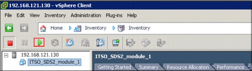
Figure 9-31 Example of virtual machine selected and green start button outlined in red
6. Connect to the IBM Spectrum Accelerate system and complete a component test of the module and phase it back into the system. Complete the following steps:
a. Connect to the IBM Spectrum Accelerate system with the IBM XIV Management GUI by using a user account that is a member of the Operations Administrator user category.
b. Browse to the system view and right-click the module in which maintenance actions were completed.
|
Tip: The module is the only one that is marked as Failed.
|
c. Right-click the module and select Test to start a component test of the module, as shown in Figure 9-32. The testing process can take some time to complete. After the testing process completes, the module is in a Ready status and can be phased into the system.

Figure 9-32 Failed module displaying selection to start component test
d. After the module completes the component testing process, start the phase in process by right-clicking the module and selecting Phase in, as shown in Figure 9-33.
|
Note: The phase in process is run in the background and completes after all the data on the system is redistributed across the entire system. The amount of time it takes to complete the phase in process can be many hours, depending on the amount of data, number of modules and disks, and the interconnect bandwidth that is allocated to the system.
|

Figure 9-33 Menu on tested module displaying selection to initiate phase in process
9.5 Disk failure and replacement
During the normal course of operation of an IBM Spectrum Accelerate system, disks can physically fail or be marked for removal from the system in accordance with the performance specifications. When this failure occurs, the IBM Spectrum Accelerate system marks the disk as failed in the Management GUI and failure events are logged. A failed disk requires physical replacement to restore proper system function.
Because of the layered nature of an IBM Spectrum Accelerate system, special care must be taken to ensure the logical disk that is marked failed within IBM Spectrum Accelerate system can be traced to the physical disk it represents. Before proceeding with any disk replacement process, ensure that the system completed the rebuild or phaseout processes to ensure the data integrity of the system. This verification can be done by reviewing the system redundancy bar in the lower right corner of the IBM XIV Management GUI or running the monitor_redist command by using IBM XIV Management XCLI utility.
The following prerequisites must be met to complete disk replacements:
•A user must be a member of the Operations Administrator user category on the IBM Spectrum Accelerate system.
•Administrative access to the VMware ESXi server with SSH or shell access must be available.
9.5.1 Replacing a disk by using the XIV GUI/XCLI and VMware vSphere Client
Complete the following steps to replace a disk:
1. Using the XCLI, ensure that the system is not in a rebuild state and did not report non-recovered medium errors for the last 8, 16, 24, or 32 days for 1 TB, 2 TB, 3 TB, or 4 TB disk systems. Complete the following steps:
a. Run the IBM XIV management XCLI state_list command (see Example 9-5 on page 260) to find the current state of the system. If the system shows that it is in a rebuild process, do not proceed with any maintenance tasks until the system is in a Full Redundancy state.
Example 9-5 Check for rebuild or redistribution state and any non-recovered medium error
XIV ITSO_SDS2>>state_list
Category Value
system_state on
target_state on
safe_mode no
shutdown_reason No Shutdown
off_type off
redundancy_status Full Redundancy
ssd_caching enabled
encryption disabled
XIV ITSO_SDS2>>
b. Ensure that the system did not detect a MEDIUM_ERROR_NOT_RECOVERED event by using the IBM XIV Management XCLI, as shown in Example 9-6. This event indicates that there was a medium error detected during rebuild. If this error is found, contact IBM Technical Support for further assistance.
|
Note: The arguments for this command require the after= value that specifies a start time for the event search.
The after= value specifies current date.hour minus 8,16, 24, or 32 days. Removal of a failed disk that has the good copy of data when a functioning disk does not prevent proper recovery and must be avoided.
|
Example 9-6 Checking the event_list to ensure no errors are present
XIV ITSO_SDS2>> event_list after=2015-02-28.16 code=MEDIUM_ERROR_NOT_RECOVERED
Timestamp Severity Code User Description
XIV ITSO_SDS2>>
XIV ITSO_SDS2>>
2. Identify the failed disk’s Reported Serial and Identifier values. Complete the following steps:
a. As a user who is assigned the Operations Administrator user category, connect to the system by using the IBM XIV Management XCLI utility.
b. Run the disk_list disk=1:Disk:XX:XX command and specify the module and disk number for the disk that failed. This command shows more information about the disk, including the Reported Serial and Identifier of the failed drive, as shown in Example 9-7.
|
Tip: The correct argument to specify a disk for the disk_list command is 1:Disk:<Module#>:<Disk#>. These values can be found by using the IBM XIV Management GUI.
|
Example 9-7 Disk list output for failed drive showing Reported Serial and Identifier numbers
XIV ITSO_SDS2>>disk_list disk=1:disk:1:1 -x
<XCLIRETURN STATUS="SUCCESS" COMMAND_LINE="disk_list disk=1:disk:1:1 -x">
<OUTPUT>
<disk id="6b51590005b">
<component_id value="1:Disk:1:1"/>
<status value="OK"/>
<currently_functioning value="yes"/>
<capacity value="2TB"/>
<target_status value=""/>
<size value="1878633"/>
<model value="ST32000444SS"/>
<original_model value="ST32000444SS"/>
<vendor value="IBM-XIV"/>
<original_vendor value="IBM-XIV"/>
<serial value="AAtjUbrJteiZusnnhvp3"/>
<original_serial value="AAtjUbrJteiZusnnhvp3"/>
<reported_serial value="9WM2XYEW"/>
<original_reported_serial value="9WM2XYEW"/>
<part_number value="45W8286"/>
<original_part_number value="45W8286"/>
<group value="A"/>
<original_group value="A"/>
<requires_service value=""/>
<service_reason value=""/>
<temperature value="0"/>
<firmware value="BC2B"/>
<original_firmware value="BC2B"/>
<revision value=""/>
<original_revision value=""/>
<drive_pn value="81Y3827"/>
<original_drive_pn value="81Y3827"/>
<device_identifier value="5000C50025DADA13"/>
<original_device_identifier value="5000C50025DADA13"/>
<encryption_state value="Not Supported"/>
<security_state value="Unchecked"/>
<security_state_last value="Unchecked"/>
<desc>
<disk_id value="1"/>
<read_fail value="no"/>
<smart_code value="NO ADDITIONAL SENSE INFORMATION"/>
<smart_fail value="no"/>
<power_on_hours value="0"/>
<power_on_minutes value="0"/>
<last_sample_time value="0"/>
<last_sample_serial value="AAtjUbrJteiZusnnhvp359WM2XYEW"/>
<last_time_pom_was_mod value="0"/>
<temperature_status>
<temperature value="0"/>
<reported_severity value="none"/>
<reported_temperature value="0"/>
</temperature_status>
<power_is_on value="no"/>
<bgd_scan value="0"/>
</desc>
<controller_type value="SAS"/>
</disk>
</OUTPUT>
</XCLIRETURN>
3. Identify the VMware ESXi server data store mapping file that correlates to the failed disk in the IBM Spectrum Accelerate system. Complete the following steps:
a. As an administrative user, connect to the VMware ESXi server that hosts the IBM Spectrum Accelerate virtual machine that contains the failed drive. The server can be accessed by using VMware vSphere client, or if vCenter is used, the VMware vSphere Web Client.
b. Right-click the IBM Spectrum Accelerate virtual machine and select Edit Settings to open the Virtual Machine Properties window. Several devices are listed, including many HDD devices.
|
Note: In addition to the HDDs that are labeled “Mapped Raw Lun”, there are HDDs that are labeled “Virtual Disk.” These HDDs are used to support IBM Spectrum Accelerate system, but are not used by the IBM Spectrum Accelerate system to store data.
|
c. To identify the correct HDD, select each HDD and review the data store mapping file name that is displayed in the right pane of the window.
d. Find the HDD that corresponds to the failed IBM Spectrum Accelerate disk and verify that the Physical LUN string contains the Identifier that is noted in previous step. The Identifier is contained within the Physical LUN string and does not comprise the entire string (see Figure 9-34).
|
Important: Make note of the Virtual Device Node of the failed disk and record it for use when the replacement disk is added to the virtual machine. As shown in Figure 9-34, the Virtual Device Node is 0:0.
|

Figure 9-34 Virtual machine Properties menu showing Physical LUN and mapping file
4. Remove the hard disk mapping file from the IBM Spectrum Accelerate virtual machine. Complete the following steps:
a. Highlight the HDD and select Remove. The right pane content changes to present removal options.
b. Select the Remove from virtual machine and delete files from disk option. Then, select OK to complete logical removal of the failed disk from the system, as shown in Figure 9-35.
Figure 9-35 Removal of HDD within the Virtual Machine Properties
5. Identify the physical HDD location by comparing the Reported Serial or Identifier numbers that are found by using the disk_list command. Record these values to the physical disk location records, which were completed when the IBM Spectrum Accelerate system or module was installed.
|
Tip: For more information about HDD location recording and labeling, see “Important considerations” on page 19.
|
6. Physically remove the failed disk and verify that the Reported Serial and Identifier number match those numbers that were recorded earlier to ensure that the correct disk was removed.
|
Note: Some disk controllers increment the Identifier (WWN) so that the last digits do not match the logically reported disk Identifier and what is physically printed on the disk, as shown in Figure 9-36.
|

Figure 9-36 Physical disk label contrasted with IBM Spectrum Accelerate disk information
7. Replace the physical disk and ensure that the new drive Reported Serial and Identifier numbers are recorded. Complete the following steps:
a. Record the replacement disk Reported Serial and Identifier (WWN) numbers from the disk label and the new disk’s physical position in the records.
|
Important: Because VMware ESXi servers add devices that are based on controller and port number, it is important that replacement disks are in the same physical location as the disk that is being replaced.
|
b. Complete physical replacement of the HDD and verify that it turns on.
c. If the controller that is used does not pass the correct Identifier (WWN) to the VMware ESXi server, the correct identifier can be found by comparing the target value of the HDDs. The newest target identifier is the correct identifier that is reported in VMware ESXi.
This information is displayed within the VMware vSphere Client by highlighting the server, opening the Configuration tab, selecting Storage, and then Devices at the top of the pane.
Each device has a runtime name that contains the adapter number, controller number, and target number within it. The target value is indicated by .T<Number>. within the runtime name string, as shown in Figure 9-37.

Figure 9-37 VMware vSphere client showing storage device configuration and runtime name
Larger target values are associated with the latest drives to be connected to the system because this value is incremented when new drives are connected.
8. Find the Physical LUN Device by using the Identifier (WWN) of the new drive, as shown in Example 9-8.
Example 9-8 Example of finding replacement disk Physical LUN Device using partial WWN
~ # ls /vmfs/devices/disks/ -la |grep -i 5000c50025dada
-rw------- 1 root root 2000398934016 Feb 20 18:18 naa.5000c50025dada13
lrwxrwxrwx 1 root root 20 Feb 20 18:18 vml.02000000005000c50025dada13535433323030 -> naa.5000c50025dada13
Complete the following steps:
a. Connect to VMware ESXi server shell by using SSH or VMware ESXi Shell as an administrative user.
b. Identify the replacement disk device name by running the ls /vmfs/devices/disks/ -la | grep -i <WWN_From_Replacement_Disk> command and searching for the WWN from the disk label.
|
Note: Depending upon the hardware disk controller, the WWN can be altered or replaced with a WWN that is issued from the controller.
|
9. Create an RDM mapping file for the HDD. Complete the following steps:
a. Run the vmkfstools -z command to create the RDM mapping file that is associated with the physical HDD. This command requires the VML device that was identified in the previous step and the location of the RDM mapping file that is created. Example 9-9 shows how to run the vmkfstools command to create the RDM mapping file.
|
Note: The RDM mapping file name must use the following form to comply with the IBM Spectrum Accelerate system:
/vmfs/volumes/MOD1_ds/data_rdm_disk_paths/DISK_XX_RDM.vmdk
When the physical device is specified in the command, the disk device node can be used instead of the Physical LUN device if the Physical LUN device is unknown.
|
Example 9-9 Creating RDM Mapping file by using Physical LUN Device and the disk device node
~ # vmkfstools -z /vmfs/devices/disks/vml.02000000005000c50025dada13535433323030 /vmfs/volumes/MOD1_ds/data_rdm_disk_paths/DISK_1_RDM.vmdk
OR
~ # vmkfstools -z /vmfs/devices/disks/naa.5000c50025dada13 /vmfs/volumes/MOD1_ds/data_rdm_disk_paths/DISK_1_RDM.vmdk
10. Use the VMware vSphere Client to add the replacement disk to the virtual machine. Complete the following steps:
a. Connect to the VMware ESXi server by using the VMWare vSphere Client or the VMware vSphere Web Client as an administrative user.
b. Right-click the IBM Spectrum Accelerate virtual machine and select Edit Settings to open the Virtual Machine Properties window.
c. Select Add from the top of the window. A new window opens. Select Hard Disk from the center pane and select Next, as shown in Figure 9-38.

Figure 9-38 Adding replacement disk to the virtual machine
d. Select the Use an existing virtual disk Reuse a previously configured virtual disk option and select Next.
e. Select Browse and browse to the RDM mapping that was created and is within the <DATASTORE_NAME>/data_rdm_disk_paths/ folder.
f. Select the correct RDM mapping file that is associated with the disk that is being replaced, as shown in Figure 9-39. Select Next.

Figure 9-39 Example selection of Disk_1_RDM.vmdk for replacement
g. Verify that the Virtual Device Node on the Advanced Options window matches the original HDD’s Virtual Device Node. Select OK to add the disk to the system.
11. Verify that the new disk is Failed, but Functioning by using the IBM XIV Management XCLI utility, as shown in Example 9-10.
Example 9-10 disk_list command
XIV ITSO_SDS2>>disk_list disk=1:disk:1:1
Component ID Status Currently Functioning Capacity
1:Disk:1:1 Failed yes 2TB
XIV ITSO_SDS2>>
|
Note: If the new disk shows functioning=yes, the disk is ready to be component tested and phased into the IBM Spectrum Accelerate system.
If the new disk shows functioning=no, verify the replacement steps, re-create the RDM mapping file, and check again. If the disk is still listed as functioning=no after completing the checks, contact IBM Technical Support for assistance.
|
12. Connect to the IBM Spectrum Accelerate system, component test, and start the phase in of the replacement HDD. Complete the following steps:
a. Connect to the IBM Spectrum Accelerate system as a user who is a member of the Operations Administrator category. Browse to the IBM Spectrum Accelerate system within the IBM XIV Management GUI.
b. Expand the Module menu for the module for which the disk replacement is being completed.
c. Expand the Disks menu to display the failed HDD. Right-click the failed HDD and select Test to start a component test of the replacement disk. Allow the drive to complete the initialization and be marked as Ready.
d. Right-click the disk and select Phase In to complete the replacement. Figure 9-40 shows an example of how the IBM XIV Management GUI displays the drive during the phase in process.
|
Note: The phase in process is run in the background and completes after all the data on the system is redistributed to account for the new disk. The amount of time it takes to complete the phase in process can span many hours, depending on the amount of data, number of modules and disks, and the interconnect bandwidth of the system.
|

Figure 9-40 Disk phasing in following completed test
9.5.2 Replacing failed disks by using XCLI and SSH
Complete the following steps to replace a failed disk by using XCLI and SSH:
1. Using the IBM XIV Management XCLI, ensure that the system is not in a rebuild state and did not report non-recovered medium errors for the last 8,16, 24, and 32 days for 1 TB, 2 TB, 3 TB, and 4 TB disk systems. Complete the following steps:
a. Connect to the IBM Spectrum Accelerate system by using the IBM XIV Management XCLI utility. Run the IBM XIV management XCLI state_list command (see Example 9-11) to determine the current state of the system. If the system shows that it is in rebuild process, delay proceeding with any maintenance actions until the system is in Full Redundancy state.
Example 9-11 Verify that the system is in a Full Redundancy status
XIV ITSO_SDS2>>state_list
Category Value
system_state on
target_state on
safe_mode no
shutdown_reason No Shutdown
off_type off
redundancy_status Full Redundancy
ssd_caching enabled
encryption Disabled
XIV ITSO_SDS2>>
b. Ensure that the system did not detect a MEDIUM_ERROR_NOT_RECOVERED event by using the IBM XIV Management XCLI, as shown in Example 9-12. This event indicates that there was a medium error detected during rebuild. If this event is found, contact IBM Technical Support for further assistance.
|
Note: The arguments for this command require the after= value to specify a start time for the event search.
The after= value specifies current date.hour minus 8,16, 24, or 32 days.
Removal of a failed disk that has the undamaged partition when the functioning disk does not prevent proper recovery and must be avoided.
|
Example 9-12 Checking the event_list
XIV ITSO_SDS2>> event_list after=2015-02-28.16 code=MEDIUM_ERROR_NOT_RECOVERED
Timestamp Severity Code User Description
XIV ITSO_SDS2>>
XIV ITSO_SDS2>>
2. Identify the failed disk’s Reported Serial and Identifier numbers. Complete the following steps:
a. As a user who is assigned the Operations Administrator user category, connect to the system by using the IBM XIV Management XCLI utility.
b. Run the disk_list disk=1:Disk:XX:XX command and specify the module and disk number for the disk that is failed. This command shows more information about the disk, including the Reported Serial and Identifier numbers of the failed drive, as shown in Example 9-13.
|
Tip: The correct argument to specify a disk for the disk_list command is 1:Disk:<Module#>:<Disk#>. These values can be found by using the IBM XIV Management GUI or running the component_list filter=notok IBM Spectrum Accelerate XCLI command.
|
Example 9-13 Disk list output for failed drive showing Reported Serial and Identifier
XIV ITSO_SDS2>>disk_list disk=1:disk:1:1 -x
<XCLIRETURN STATUS="SUCCESS" COMMAND_LINE="disk_list disk=1:disk:1:1 -x">
<OUTPUT>
<disk id="6b51590005b">
<component_id value="1:Disk:1:1"/>
<status value="OK"/>
<currently_functioning value="yes"/>
<capacity value="2TB"/>
<target_status value=""/>
<size value="1878633"/>
<model value="ST32000444SS"/>
<original_model value="ST32000444SS"/>
<vendor value="IBM-XIV"/>
<original_vendor value="IBM-XIV"/>
<serial value="AAtjUbrJteiZusnnhvp3"/>
<original_serial value="AAtjUbrJteiZusnnhvp3"/>
<reported_serial value="9WM2XYEW"/>
<original_reported_serial value="9WM2XYEW"/>
<part_number value="45W8286"/>
<original_part_number value="45W8286"/>
<group value="A"/>
<original_group value="A"/>
<requires_service value=""/>
<service_reason value=""/>
<temperature value="0"/>
<firmware value="BC2B"/>
<original_firmware value="BC2B"/>
<revision value=""/>
<original_revision value=""/>
<drive_pn value="81Y3827"/>
<original_drive_pn value="81Y3827"/>
<device_identifier value="5000C50025DADA13"/>
<original_device_identifier value="5000C50025DADA13"/>
<encryption_state value="Not Supported"/>
<security_state value="Unchecked"/>
<security_state_last value="Unchecked"/>
<desc>
<disk_id value="1"/>
<read_fail value="no"/>
<smart_code value="NO ADDITIONAL SENSE INFORMATION"/>
<smart_fail value="no"/>
<power_on_hours value="0"/>
<power_on_minutes value="0"/>
<last_sample_time value="0"/>
<last_sample_serial value="AAtjUbrJteiZusnnhvp359WM2XYEW"/>
<last_time_pom_was_mod value="0"/>
<temperature_status>
<temperature value="0"/>
<reported_severity value="none"/>
<reported_temperature value="0"/>
</temperature_status>
<power_is_on value="no"/>
<bgd_scan value="0"/>
</desc>
<controller_type value="SAS"/>
</disk>
</OUTPUT>
</XCLIRETURN>
3. Find the Virtual Machine ID of the IBM Spectrum Accelerate virtual machine, as shown in Example 9-14.
Example 9-14 Finding the VMID of the virtual machine by using the vim-cmd utility
~ $vim-cmd vmsvc/getallvms
Vmid Name File
16 ITSO_SDS2_module_1 [MOD1_ds] ITSO_SDS2_module_1/ITSO_SDS2_module_1.vmx
Guest OS Version Annotation
other26xLinux64Guest vmx-08
Complete the following steps:
a. Use SSH to connect to the VMware ESXi server that hosts the IBM Spectrum Accelerate module’s virtual machine with an administrative user.
b. Identify the VMID of the IBM Spectrum Accelerate virtual machine by running the vim-cmd vmsvc/getallvms command.
4. Display information about the hardware devices that are used by the IBM Spectrum Accelerate virtual machine. Complete the following steps:
a. Run the vim-cmd vmsvc/device.getdevices $VMID command by using the Virtual Machine ID that was found in the previous step, as shown in Example 9-15 on page 272.
|
Note: The vim-cmd vmsvc/device.getdevices $VMID command gathers all of the basic information for the hardware components in the server. It also displays information about how they are mapped to the virtual machines.
|
b. The disk drive information can be identified in the output of the command. Search for the Identifier (WWN) number to correctly identify the section that contains the information that is related to the failed disk.
c. Make a note of the controllerKey and unitNumber that correspond to the Virtual Device Node of the HDD that is assigned to the virtual machine. As shown in Example 9-15 on page 272, the controllerKey is 1000 and the unitNumber is 0. This information corresponds to Virtual Device Node SCSI 0:0.
|
Important: Record for future reference the Virtual Device Node of the failed disk. The Virtual Device Node is used mapping the replacement HDD to the virtual machine.
|
Example 9-15 Output of vim-cmd vmsvc/device.getdevices with required values
~ # vim-cmd vmsvc/device.getdevices 16
....
(vim.vm.device.VirtualDisk) {
dynamicType = <unset>,
key = 2000,
deviceInfo = (vim.Description) {
dynamicType = <unset>,
label = "Hard disk 13",
summary = "1,953,514,584 KB",
},
backing = (vim.vm.device.VirtualDisk.RawDiskMappingVer1BackingInfo) {
dynamicType = <unset>,
fileName = "[MOD1_ds] data_rdm_disk_paths/DISK_1_RDM.vmdk",
Data store = 'vim.Datastore:54d2547f-817c0fe8-1d0c-001b2191d450',
backingObjectId = <unset>,
lunUuid = "02000000005000c50025dada13535433323030",
deviceName = "vml.02000000005000c50025dada13535433323030",
compatibilityMode = "physicalMode",
diskMode = "independent_persistent",
uuid = <unset>,
contentId = <unset>,
changeId = <unset>,
parent = (vim.vm.device.VirtualDisk.RawDiskMappingVer1BackingInfo) null,
deltaDiskFormat = <unset>,
deltaGrainSize = <unset>,
},
connectable = (vim.vm.device.VirtualDevice.ConnectInfo) null,
slotInfo = (vim.vm.device.VirtualDevice.BusSlotInfo) null,
controllerKey = 1000,
unitNumber = 0,
capacityInKB = 1953514584,
capacityInBytes = 2000398934016,
shares = (vim.SharesInfo) {
dynamicType = <unset>,
shares = 1000,
level = "normal",
},
storageIOAllocation = (vim.StorageResourceManager.IOAllocationInfo) {
dynamicType = <unset>,
limit = -1,
shares = (vim.SharesInfo) {
dynamicType = <unset>,
shares = 1000,
level = "normal",
},
reservation = 0,
},
....
5. Remove the failed HDD from the virtual machine configuration. Complete the following steps:
a. Disconnect the failed HDD from the IBM Spectrum Accelerate virtual machine by running the vim-cmd vmsvc/device.diskremove command (see Example 9-16) and supplying the appropriate arguments to identify the correct virtual machine and HDD.
|
Note: Use the VMID of the virtual machine and the controllerKey and unitNumber as the identifying arguments to remove the HDD from the virtual machine.
|
The final argument for the vim-cmd vmsvc/device.diskremove command is confirmation that all files were deleted from HDD. If the command is created correctly, the HDD is removed from the IBM Spectrum Accelerate virtual machine.
|
Tip: It is suggested that you connect to the system to ensure that no other HDDs were marked as failed after running the disk removal.
|
Example 9-16 Removing the failed hard disk from the virtual machine configuration
~ # vim-cmd vmsvc/device.diskremove
Usage: device.diskremove ‘vmid’ ‘controller number’ ‘unit number’ ‘delete file’
~ # vim-cmd vmsvc/device.diskremove 16 0 0 y
6. Identify the HDD data store Mapping File and remove it. Example 9-17 on page 273 shows identifying, removing, and verifying that the HDD data store Mapping File was removed. Complete the following steps:
a. Identify the failed HDD data store mapping file by running the ls -l /vmfs/volumes/{data store}/data_rdm_disk_paths command.
|
Note: The disk number matches the drive number that is marked failed by IBM Spectrum Accelerate system.
|
b. Remove the data store mapping file by running the vmkfstools -U command against the mapping file. The command completes with no output.
|
Tip: Run the ls -l /vmfs/volumes/{data store}/data_rdm_disk_paths command to ensure that data store mapping file was removed.
|
Example 9-17 Removing the failed HDD from the VMWare server inventory
~ # ls /vmfs/volumes/MOD1_ds/data_rdm_disk_paths/
DISK_10_RDM-rdmp.vmdk DISK_3_RDM-rdmp.vmdk DISK_7_RDM-rdmp.vmdk
DISK_10_RDM.vmdk DISK_3_RDM.vmdk DISK_7_RDM.vmdk
DISK_11_RDM-rdmp.vmdk DISK_4_RDM-rdmp.vmdk DISK_8_RDM-rdmp.vmdk
DISK_11_RDM.vmdk DISK_4_RDM.vmdk DISK_8_RDM.vmdk
DISK_1_RDM-rdmp.vmdk DISK_5_RDM-rdmp.vmdk DISK_9_RDM-rdmp.vmdk
DISK_1_RDM.vmdk DISK_5_RDM.vmdk DISK_9_RDM.vmdk
DISK_2_RDM-rdmp.vmdk DISK_6_RDM-rdmp.vmdk
DISK_2_RDM.vmdk DISK_6_RDM.vmdk
~ # vmkfstools -U /vmfs/volumes/MOD1_ds/data_rdm_disk_paths/DISK_1_RDM.vmdk
~ # ls /vmfs/volumes/MOD1_ds/data_rdm_disk_paths/
DISK_10_RDM-rdmp.vmdk DISK_11_RDM.vmdk DISK_3_RDM-rdmp.vmdk DISK_4_RDM.vmdk DISK_6_RDM-rdmp.vmdk DISK_7_RDM.vmdk DISK_9_RDM-rdmp.vmdk
DISK_10_RDM.vmdk DISK_2_RDM-rdmp.vmdk DISK_3_RDM.vmdk DISK_5_RDM-rdmp.vmdk DISK_6_RDM.vmdk DISK_8_RDM-rdmp.vmdk DISK_9_RDM.vmdk
DISK_11_RDM-rdmp.vmdk DISK_2_RDM.vmdk DISK_4_RDM-rdmp.vmdk DISK_5_RDM.vmdk DISK_7_RDM-rdmp.vmdk DISK_8_RDM.vmdk
7. Physically remove the HDD and verify that the Reported Serial and Identifier numbers match the numbers that were reported by the IBM Spectrum Accelerate system software to ensure that the correct HDD was removed.
|
Note: Some disk controllers logically increment the Identifier (WWN) so that the last digits no longer matches what is physically printed on the disk.
Figure 9-41 shows an example of an incremented reported Identifier compared to the WWN number that is physically printed on the HDD.
|

Figure 9-41 Physical disk label contrasted with IBM Spectrum Accelerate disk information
8. Replace the physical HDD and ensure that the new drives Serial and Identifier (WWN) numbers are recorded. Complete the following steps:
a. Record the replacement HDD’s Serial and Identifier (WWN) numbers from label and record the physical position of the new disk in the records.
|
Important: Because VMware adds devices that are based on controller and port number, it is important that replacement disks are installed in the same physical location as the disk that is being replaced.
|
b. Complete the physical replacement of the HDD and verify that it powers on and that no physical error indicator lights are present.
9. Find the Physical LUN Device (as reported by VMware ESXi) by using the Identifier (WWN) of the new HDD. Complete the following steps:
a. Connect to VMware ESXi server as an administrative user by using e SSH or VMware ESXi Shell.
b. Identify the replacement HDD name by running the ls /vmfs/devices/disks/ -la | grep -i <WWN_From_Replacement_Disk> command and searching for the Identifier (WWN) that was printed on the drive label.
Example 9-18 shows an example of search for the replacement HDD by Indentifier (WWN).
|
Note: Some hardware disk controllers can alter or even replace the disk Identifier (WWN) with a different WWN that is issued by the disk controller.
|
Example 9-18 Example of finding replacement disk Physical LUN Device using partial WWN
~ # ls /vmfs/devices/disks/ -la |grep -i 5000c50025dada
-rw------- 1 root root 2000398934016 Feb 20 18:18 naa.5000c50025dada13
lrwxrwxrwx 1 root root 20 Feb 20 18:18 vml.02000000005000c50025dada13535433323030 -> naa.5000c50025dada13
10. Create an RDM mapping file for the HDD. Complete the following steps:
a. Run the vmkfstools -z command to create the RDM mapping file that is associated with the physical HDD. This command requires the VML device that was identified in the previous step and the location of the RDM mapping file that is created. Example 9-19 shows how to run the vmkfstools command to create the RDM mapping file.
|
Note: The RDM mapping file must use the following naming convention be compliant with the IBM Spectrum Accelerate system:
/vmfs/volumes/MOD1_ds/data_rdm_disk_paths/DISK_XX_RDM.vmdk
When the physical device is specified in the command, the disk device node can be used instead of the Physical LUN device if the Physical LUN device is unknown.
|
Example 9-19 Creating RDM Mapping file
~ # vmkfstools -z /vmfs/devices/disks/vml.02000000005000c50025dada13535433323030 /vmfs/volumes/MOD1_ds/data_rdm_disk_paths/DISK_1_RDM.vmdk
OR
~ # vmkfstools -z /vmfs/devices/disks/naa.5000c50025dada13 /vmfs/volumes/MOD1_ds/data_rdm_disk_paths/DISK_1_RDM.vmdk
11. Because of limitations of the VMware ESXi command-line interface, the replacement procedure must be completed by using the VMware vSphere client. Complete the remainder of the HDD replacement process by starting at step 10 on page 266.
9.6 SSD failure and replacement
SSDs are used as a read cache in IBM Spectrum Accelerate systems. Throughout the normal course of operation, SSDs can physically fail or be removed from an IBM Spectrum Accelerate system in accordance with the performance specifications or as a result of hardware failure.
Before proceeding with any SSD replacement process, verify that the system completed any rebuild or redistribution processes to ensure data integrity. Check the system redundancy bar in the lower right corner of the IBM XIV management GUI or run the monitor_redist IBM XIV Management XCLI command.
The following prerequisites must be met to successfully complete replacing SSD devices:
•Use an IBM Spectrum Accelerate system user account that is a member of the Operation Administrator user category.
•Have administrative access to the VMware ESXi server with SSH or shell access.
9.6.1 SSD replacement by using the GUI/XCLI and VMware vSphere Client
Complete the following steps to replace an SSD by using the GUI/XCLI and VMware vSphere Client:
1. Using the IBM XIV Management XCLI, ensure that the IBM Spectrum Accelerate system is not in a rebuild or redistribution state.
Connect to the IBM Spectrum Accelerate system with a user account that is a member of the Operations Administrator category and run the state_list command to find the current state of the system, as shown in Example 9-20.
|
Note: If the system is in a rebuild or redistribution process, do not proceed with physical removal of the SSD until the system is in a Full Redundancy status.
|
Example 9-20 Check for full redundancy and no rebuild or redistribution
XIV itso_sds10>>state_list
Category Value
system_state on
target_state on
safe_mode no
shutdown_reason No Shutdown
off_type off
redundancy_status Full Redundancy
ssd_caching enabled
encryption Not Supported
2. Find the SSD Reported Serial and Part number. Complete the following steps:
a. Run the ssd_list -x command and specify the failed disk. Record the Reported Serial and Part number of the SSD drive. The syntax for the ssd_list -x command to specify a specific SSD is ssd_list ssd=1:ssd:[Module#]:[SSD#] -x, as shown in Example 9-21.
|
Tip: The SSD information can be obtained from within the IBM XIV Management GUI.
|
Example 9-21 SSD list output for failed drive showing Reported Serial and Part Number
XIV itso_sds10>>ssd_list ssd=1:ssd:4:1 -x
<XCLIRETURN STATUS="SUCCESS" COMMAND_LINE="ssd_list ssd=1:ssd:4:1 -x">
<OUTPUT>
<ssd id="63e15a0000a">
<component_id value="1:SSD:4:1"/>
<status value="OK"/>
<currently_functioning value="yes"/>
<capacity value="524GB"/>
<target_status value=""/>
<size value="500000"/>
<model value="MTFDDAA800MBB-1AE12A"/>
<original_model value="MTFDDAA800MBB-1AE12A"/>
<vendor value="XIV"/>
<original_vendor value="XIV"/>
<serial value="DpwvqmqldmimmhkmjmkV"/>
<original_serial value="DpwvqmqldmimmhkmjmkV"/>
<reported_serial value="03873A61"/>
<original_reported_serial value="03873A61"/>
<part_number value="98Y5060"/>
<original_part_number value="98Y5060"/>
<group value=""/>
<original_group value=""/>
<requires_service value=""/>
<service_reason value=""/>
<temperature value="0"/>
<firmware value="MB29"/>
<original_firmware value="MB29"/>
<revision value=""/>
<original_revision value=""/>
<drive_pn value="98Y5061"/>
<original_drive_pn value="98Y5061"/>
<device_identifier value="2020202020202020"/>
<original_device_identifier value="2020202020202020"/>
<desc>
<last_sample_serial value="DpwvqmqldmimmhkmjmkVV03873A61"/>
<temperature_status>
<temperature value="0"/>
<reported_severity value="none"/>
<reported_temperature value="0"/>
</temperature_status>
<last_sample_time value="0"/>
<power_on_hours value="0"/>
<block_wear_leveling value="0"/>
<secure_erase_status value="NEVER_ERASED"/>
</desc>
<encryption_state value="Uninitialized"/>
</ssd>
</OUTPUT>
</XCLIRETURN>
3. Remove the VMware datastore mapping file for the failed SSD. Complete the following steps:
a. Connect as an administrative user to the VMware ESXi server that contains the IBM Spectrum Accelerate system. The server can be accessed by using VMware vSphere Client or (if vCenter is used) the VMware vSphere Web Client.
b. Right-click the IBM Spectrum Accelerate virtual machine and select Edit Settings to open the Virtual Machine Properties window.
|
Note: The user is presented with several devices, including many HDDs. In addition to the HDDs that are labeled “Mapped Raw Lun,” there are more disks that are labeled “Virtual Disk” that are used to support IBM Spectrum Accelerate but are not used for storing data.
|
c. To identify the correct HDD, highlight each HDD and review the data store mapping file location and name that are displayed in the right pane.
d. Find the HDD device that corresponds to the failed IBM Spectrum Accelerate SSD by reviewing the data store mapping file location and ensuring that it is in [data store]/ssd_rdm_disk_paths/. The SSD is labeled as DISK_1_RDM.vmdk within that folder, as shown in Figure 9-42.

Figure 9-42 Identifying SSD by Physical LUN and data store Mapping File
4. When the SSD is highlighted, select Remove. Removal options are then shown in the right-side pane.
5. Select Remove from virtual machine and delete files from disk and then, select OK to remove the failed SSD from the system, as shown in Figure 9-43.
Figure 9-43 Completing removal of SSD from the virtual machine
6. Complete the physical replacement of the SSD. Complete the following steps:
a. Physically remove the failed SSD and verify that the Serial number and Part Number match those numbers that were reported by the IBM Spectrum Accelerate system to ensure that the correct SSD was removed.
b. Record the Serial Number and Part number of the new SSD.
c. Physically install the replacement SSD in the VMware ESXi server.
7. Rescan the local storage devices to bring the new SSD into the storage device inventory by selecting Configuration → Storage → Devices → Rescan All. Select the Scan for New Storage Devices option, then the Scan for New VMFS Volumes option, and then, select OK.
8. Identify the Physical LUN Device of the new SSD in the VMware ESXi server. Complete the following steps:
a. Connect to VMware ESXi server shell as an administrative user by using SSH or the VMware vSphere Shell.
b. Identify the logical replacement SSD device name by running the ls /vmfs/devices/disks/ -la | grep -i <SERIAL_NUMBER> command that uses the serial number from the SSD label, as shown in Example 9-22.
Example 9-22 Finding replacement SSD Physical LUN Device
~ ## ls /vmfs/devices/disks |grep -i 03873a61
t10.ATA_____MTFDDAA800MBB2D1AE12A_98Y5060_98Y5061XIV_____________03873A61 
9. Verify that the SSD RDM folder is on the VMware ESXi server data store. If there was only one SSD installed in the server at the time the SSD was removed from the virtual machine, the folder on the data store was automatically removed. Complete the following steps:
a. Run the ls /vmfs/volumes/[DATA_STORE_NAME]/ command to find if the folder ssd_rdm_disk_paths exists.
b. If the folder ssd_rdm_disk_paths does not exist, run the mkdir -p /vmfs/volumes/[DATA_STORE_NAME]/ssd_rdm_disk_paths command to create the ssd_rdm_disk_paths folder on the data store.
|
Note: If there are multiple data stores that are mounted to the VMware ESXi host, ensure that the correct one is used to create the RDM mapping file for the SSD drive.
|
10. Create an RDM mapping file for the SSD, as shown in Example 9-23. Run the vmkfstools -z command by using the Physical LUN device. The RDM mapping file is created on the data store that was verified in step 8.
|
Note: The SSD device node can be used within the command directly instead of the Physical LUN device if the Physical LUN device is unknown.
|
Example 9-23 RDM Mapping file creation using Physical LUN Device or the disk device node
~ # vmkfstools -z /vmfs/devices/disks/t10.ATA_____MTFDDAA800MBB2D1AE12A_98Y5060_98Y5061XIV_____________03873A61 /vmfs/volumes/MOD1_ds/ssd_rdm_disk_paths/DISK_1_RDM.vmdk
OR
~ # vmkfstools -z /vmfs/devices/disks/vml.010000000020202020202020202020202030333837334136314d5446444441 /vmfs/volumes/MOD1_ds/ssd_rdm_disk_paths/DISK_1_RDM.vmdk
11. Add the SSD to the IBM Spectrum virtual machine. Complete the following steps:
a. Connect to the VMware ESXi server as an administrative user by using the VMWare vSphere Client or the VMware vSphere Web Client if a vCenter is being used.
b. Right-click the IBM Spectrum Accelerate virtual machine and select Edit Settings to open the Virtual Machine Properties window.
c. Select Add at the top of the window.

Figure 9-44 Adding replacement SSD to the virtual machine
e. Select Use an existing virtual disk Reuse a previously configured virtual disk. Select Next.
f. Select Browse and browse to the RDM mapping file that was created in the <DATASTORE_NAME>/ssd_rdm_disk_paths/ folder.
g. Highlight the RDM mapping file that corresponds to the SSD that was replaced and select OK.
h. Select Next to open the Advanced Options window and review the Virtual Device Node settings.
i. Ensure that the SSD is not using the same virtual SCSI controller as the data HDDs, as shown in Figure 9-45.
|
Note: This value often must be changed from SCSI 0:# to SCSI 1:0.
|

Figure 9-45 Changing the Virtual Device Node to SCSI (1.0) from SCSI (0.12)
|
Note: Unless the SSD is set to use a separate Virtual Device Node SCSI controller (In this case, SCSI 1:0), the IBM Spectrum Accelerate system cannot find the SSD during the testing phase.
|
12. Start a component test and phase in of the SSD to bring the replacement into the IBM Spectrum Accelerate system. Complete the following steps:
a. Connect to the IBM Spectrum Accelerate system by using the IBM XIV Management GUI with a user account that is a member of the Operations Administrator user category.
b. Expand the SSD menu on the module that contains the failed SSD.
c. Right-click the failed SSD and select Test.
d. Allow the SSD to complete initialization, as shown in Figure 9-46 on page 283. Verify that the SSD is in a Ready state.

Figure 9-46 SSD initializing following replacement and remapping of the mapping file
e. Right-click the SSD and select Phase In to complete the replacement and have the IBM Spectrum Accelerate system use the SSD.
9.6.2 Replacing the SSD by using the IBM XIV Management XCLI and SSH
Complete the following steps to replace the SSD by using the IBM XIV Management XCLI and SSH:
1. Using the IBM XIV Management System XCLI, ensure that the system is not in a rebuild state. Complete the following steps:
a. Connect to the IBM Spectrum Accelerate system with the IBM XIV Management XCLI utility with a user who is a member of the Operations Administrator user category.
b. Run the state_list command (as shown in Example 9-24) to find the state of the system. If the system is conducting a rebuild or in a redistribution process, do not remove the SSD until the system is in Full Redundancy status.
Example 9-24 Check for full redundancy and no rebuild or redistribution
XIV itso_sds10>>state_list
Category Value
system_state on
target_state on
safe_mode no
shutdown_reason No Shutdown
off_type off
redundancy_status Full Redundancy
ssd_caching enabled
encryption NotSupported
c. Run the ssd_list -x command and specify the failed disk. Record the Reported Serial and Part number of the SSD drive. The syntax for the ssd_list -x command to specify a specific SSD is ssd_list ssd=1:ssd:[Module#]:[SSD#] -x, as shown in Example 9-25.
|
Tip: The ssd information can be obtained from within the IBM XIV Management GUI.
|
Example 9-25 SSD list output for failed drive showing Reported Serial and Part Number
XIV itso_sds10>>ssd_list ssd=1:ssd:4:1 -x
<XCLIRETURN STATUS="SUCCESS" COMMAND_LINE="ssd_list ssd=1:ssd:4:1 -x">
<OUTPUT>
<ssd id="63e15a0000a">
<component_id value="1:SSD:4:1"/>
<status value="OK"/>
<currently_functioning value="yes"/>
<capacity value="524GB"/>
<target_status value=""/>
<size value="500000"/>
<model value="MTFDDAA800MBB-1AE12A"/>
<original_model value="MTFDDAA800MBB-1AE12A"/>
<vendor value="XIV"/>
<original_vendor value="XIV"/>
<serial value="DpwvqmqldmimmhkmjmkV"/>
<original_serial value="DpwvqmqldmimmhkmjmkV"/>
<reported_serial value="03873A61"/>
<original_reported_serial value="03873A61"/>
<part_number value="98Y5060"/>
<original_part_number value="98Y5060"/>
<group value=""/>
<original_group value=""/>
<requires_service value=""/>
<service_reason value=""/>
<temperature value="0"/>
<firmware value="MB29"/>
<original_firmware value="MB29"/>
<revision value=""/>
<original_revision value=""/>
<drive_pn value="98Y5061"/>
<original_drive_pn value="98Y5061"/>
<device_identifier value="2020202020202020"/>
<original_device_identifier value="2020202020202020"/>
<desc>
<last_sample_serial value="DpwvqmqldmimmhkmjmkVV03873A61"/>
<temperature_status>
<temperature value="0"/>
<reported_severity value="none"/>
<reported_temperature value="0"/>
</temperature_status>
<last_sample_time value="0"/>
<power_on_hours value="0"/>
<block_wear_leveling value="0"/>
<secure_erase_status value="NEVER_ERASED"/>
</desc>
<encryption_state value="Uninitialized"/>
</ssd>
</OUTPUT>
</XCLIRETURN>
2. Find the Virtual Machine ID of the IBM Spectrum Accelerate virtual machine. Complete the following steps:
a. Connect to the VMware ESXi server that hosts the IBM Spectrum Accelerate virtual machine as an administrative user.
b. Identify the VMID of the IBM Spectrum Accelerate virtual machine by running the vim-cmd vmsvc/getallvms command, as shown in Example 9-26.
Example 9-26 Finding the VMID of the virtual machine using the vim-cmd utility
~ $vim-cmd vmsvc/getallvms
Vmid Name File
16 ITSO_SDS2_module_1 [MOD1_ds] ITSO_SDS2_module_1/ITSO_SDS2_module_1.vmx
Guest OS Version Annotation
other26xLinux64Guest vmx-08
3. Display information about the hardware devices that are used by IBM Spectrum Accelerate virtual machine, as shown in Example 9-27. Complete the following steps:
a. Run the vim-cmd vmsvc/device.getdevices [VMID#] command with the VMID of the IBM Spectrum Accelerate system virtual machine.
|
Note: The vim-cmd vmsvc/device.getdevices [VMID#] command gathers all of the basic hardware information of the hardware components within the server and how they are mapped to the virtual machines.
|
b. Contained in the output of the command is the SSD information for the failed drive. Search for the VirtualDisk device that is mapped to an RDM file that is contained in the ssd_rdm_disk_paths folder.
|
Important: If there are multiple SSDs, this method does not help identify the correct SSD. In this case, use the VMware vSphere client to correctly identify the SSD.
|
c. Record the controllerKey and unitNumber.
|
Note: Example 9-27 shows a controllerKey value of 1001 (Controller 1) and a unitNumber value of 0 (Slot 1 on Controller 1).
|
Example 9-27 Output of vim-cmd vmsvc/device.getdevices with required values
~ # vim-cmd vmsvc/device.getdevices 16
....
(vim.vm.device.VirtualDisk) {
dynamicType = <unset>,
key = 2016,
deviceInfo = (vim.Description) {
dynamicType = <unset>,
label = "Hard disk 14",
summary = "781,412,184 KB",
},
backing = (vim.vm.device.VirtualDisk.RawDiskMappingVer1BackingInfo) {
dynamicType = <unset>,
fileName = "[h257] ssd_rdm_disk_paths/DISK_1_RDM.vmdk",
Data store = 'vim.Datastore:53d2c109-4f66c8e8-7356-0050cc69216b',
backingObjectId = <unset>,
lunUuid = "010000000020202020202020202020202030333837334136314d5446444441",
deviceName = "vml.010000000020202020202020202020202030333837334136314d5446444441",
compatibilityMode = "physicalMode",
diskMode = "independent_persistent",
uuid = <unset>,
contentId = <unset>,
changeId = <unset>,
parent = (vim.vm.device.VirtualDisk.RawDiskMappingVer1BackingInfo) null,
deltaDiskFormat = <unset>,
deltaGrainSize = <unset>,
},
connectable = (vim.vm.device.VirtualDevice.ConnectInfo) null,
slotInfo = (vim.vm.device.VirtualDevice.BusSlotInfo) null,
controllerKey = 1001,
unitNumber = 0,
capacityInKB = 781412184,
capacityInBytes = 800166076416,
shares = (vim.SharesInfo) {
dynamicType = <unset>,
shares = 1000,
level = "normal",
},
storageIOAllocation = (vim.StorageResourceManager.IOAllocationInfo) {
dynamicType = <unset>,
limit = -1,
shares = (vim.SharesInfo) {
dynamicType = <unset>,
shares = 1000,
level = "normal",
},
reservation = 0,
},
diskObjectId = "2-2016",
vFlashCacheConfigInfo = (vim.vm.device.VirtualDisk.VFlashCacheConfigInfo) null,
},
....
4. Logically remove the failed SSD from the virtual machine configuration. Complete the following steps:
a. Disconnect the failed SSD from the IBM Spectrum Accelerate virtual machine by running the vim-cmd vmsvc/device.diskremove command, as shown in Example 9-28 on page 287. Use the appropriate arguments to identify the correct virtual machine and SSD.
|
Note: Use the VMID of the virtual machine and the controllerKey and unitNumber as the identifying arguments to remove the SSD from the virtual machine.
|
The final argument for the vim-cmd vmsvc/device.diskremove command is y and represents confirmation removal of the device and deletion of all files on the SSD. If the command is run correctly, the SSD is removed from the IBM Spectrum Accelerate virtual machine.
|
Tip: It is suggested to connect to the system to ensure that no other SSDs are marked as failed.
|
Example 9-28 Removing the failed SSD from the virtual machine configuration
~ # vim-cmd vmsvc/device.diskremove
Usage: device.diskremove ‘vmid’ ‘controller number’ ‘unit number’ ‘delete file’
~ # vim-cmd vmsvc/device.diskremove 16 0 0 y
5. Identify the disk data store Mapping File and remove it from the VMware ESXi server, as shown in Example 9-29. Complete the following steps:
a. Identify the failed SSD data store mapping file name by running the ls -l /vmfs/volumes/{data store}/ssd_rdm_disk_paths command.
b. Remove the data store mapping file by running the vmkfstools -U command on the mapping file that was identified in Step 5a. The command completes with no output.
c. Run a final ls -l /vmfs/volumes/{data store}/ssd_rdm_disk_paths command to ensure that the data store mapping file was removed.
Example 9-29 Removing the failed SSD from the VMWare ESXi server inventory
~ # ls /vmfs/volumes/MOD1_ds/ssd_rdm_disk_paths/
DISK_1_RDM-rdmp.vmdk DISK_1_RDM.vmdk
~ # vmkfstools -U /vmfs/volumes/MOD1_ds/ssd_rdm_disk_paths/DISK_1_RDM.vmdk
~ # ls /vmfs/volumes/MOD1_ds/ssd_rdm_disk_paths/
~ #
6. Complete the process to physically replace the SSD. Complete the following steps:
a. Physically replace the failed SSD and verify the Serial number and Part Number match what the IBM Spectrum Accelerate system reported.
b. Record the Serial Number and Part Number of the new SSD.
c. Physically install the replacement SSD into the VMware ESXi server.
7. Identify the Physical LUN Device of the new SSD on the VMware server. Complete the following steps:
a. Connect to VMware ESXi server as an administrative user by using SSH or the VMware vSphere Shell.
b. Identify the replacement SSD device name by running the ls /vmfs/devices/disks/ -la | grep -i <Serial_Number> command to find the serial number from the SSD label, as shown in Example 9-30.
Example 9-30 Finding replacement logical SSD device by using SSD serial number
~ ## ls /vmfs/devices/disks |grep -i 03873a61
t10.ATA_____MTFDDAA800MBB2D1AE12A_98Y5060_98Y5061XIV_____________03873A61
c. If the SSD cannot be identified by using the Serial Number, search for the block device.
8. Verify that the SSD RDM folder is on the VMware server data store. If there was only one SSD installed in the server at the time the SSD was removed from the virtual machine, the folder on the data store was automatically removed. Complete the following steps:
a. Run the ls /vmfs/volumes/[DATA_STORE_NAME]/ command to find if the ssd_rdm_disk_paths folder exists.
b. If the folder ssd_rdm_disk_paths does not exist, run the mkdir -p /vmfs/volumes/[DATA_STORE_NAME]/ssd_rdm_disk_paths command to create the ssd_rdm_disk_paths folder on the data store.
|
Note: If there are multiple data stores that are mounted to the VMware ESXi server, ensure that the correct data store is used to create the RDM mapping file for the SSD drive.
|
9. Create an RDM mapping file for the SSD, as shown in Example 9-31. Run the vmkfstools -z command by using the Physical LUN device. This process creates the RDM mapping file on the data store that was verified in step 8.
|
Note: The SSD device node can be used within the command directly instead of the Physical LUN device if the Physical LUN device is unknown.
|
Example 9-31 Creating RDM Mapping file by using Physical LUN Device and disk device node
~ # vmkfstools -z /vmfs/devices/disks/t10.ATA_____MTFDDAA800MBB2D1AE12A_98Y5060_98Y5061XIV_____________03873A61 /vmfs/volumes/MOD1_ds/ssd_rdm_disk_paths/DISK_1_RDM.vmdk
OR
vmkfstools -z /vmfs/devices/disks/vml.010000000020202020202020202020202030333837334136314d5446444441 /vmfs/volumes/MOD1_ds/ssd_rdm_disk_paths/DISK_1_RDM.vmdk
10. Because of the limitations of the VMware ESXi command-line interface, the replacement procedure must be completed by using the VMware vSphere client. Complete the remainder of the SSD replacement process by using the steps in the previous section starting at step 11 on page 280.
9.7 Handling a module failure
One of the components of an IBM Spectrum Accelerate system that might fail is a module. A module at the IBM Spectrum Accelerate layer is directly associated with an VMware ESXi server at the VMware level. Each VMware ESXi server hosts a single IBM Spectrum Accelerate virtual machine that is running IBM Spectrum Accelerate system software.
A module can fail at various levels including, at the IBM Spectrum Accelerate system software level, at the VMware ESXi server level, and at the hardware level. Various recovery or replacement procedures are used to recover from the failure, depending on which layer the failure occurred.
9.7.1 Case 1: Module failure at the IBM Spectrum Accelerate system software level
A module failure at the IBM Spectrum Accelerate system software level occurs when a module is marked as failed in the IBM XIV Management GUI, but the VMware ESXi server indicates that the virtual machine is Powered On.
The recovery process requires a user who is a member of the Operation Administrator user category on the impacted IBM Spectrum Accelerate system.
Typical module failure at IBM Spectrum Accelerate system software level
This example assumes that a module failed because the network connections for the Interconnect network temporarily lost connectivity.
In this example, only a single module is affected by the network loss and is failed by the IBM Spectrum Accelerate cluster. This issue occurs because the IBM Spectrum Accelerate cluster requires connectivity to all modules in the cluster and if a module becomes isolated from the other modules, no data can be transmitted.
The remaining modules in the cluster report a NETWORK_LINK_NO_DATA event for the two Interconnection ports on the failed module. The isolated module was excluded from the cluster and is in a failed state. Because of the inherent redundancy and spare capacity built into the system, the IBM Spectrum Accelerate system remains running and servicing data.
|
Note: If Proactive Support is configured on the IBM Spectrum Accelerate system, IBM Technical support automatically is updated with the events and can notify the primary contact in these types of instances.
|
Figure 9-47 shows a system that is experiencing some type of failure.

Figure 9-47 System with a red triangle indicating a failure
When dealing with this type of failure, complete the following steps to restore the system:
1. To obtain more information about the problem, click the system icon to browse to the system view. Module:3 and all of its disks are in failed state, as shown in Figure 9-48.

Figure 9-48 Module:3 is in failed state
2. The system events provide more information about the cause for the failure. Open the Events window by selecting System → Events, as shown in Figure 9-49.

Figure 9-49 Opening the Events view
3. Checking the system events that are shown in Figure 9-50 reveals that before the Module:3 failure, a NETWORK_LINK_NO_DATA event was posted by the functioning modules (1, 2, and 4). Because Module:3 never posted this error, the logical conclusion is that Module:3 lost connectivity to both of its interconnect links.
|
Note: Without interconnect connections, a module cannot send or receive data to or from any other module and is of no use to the system.
|

Figure 9-50 Module:3 failure because of lost interconnects
Looking at the VMware ESXi server, the use of the VMware vSphere client as shown in Figure 9-51 shows that the IBM Spectrum Accelerate virtual machine status is Powered On and not reporting any errors.
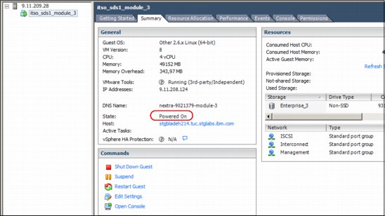
Figure 9-51 Status of the hosting virtual machine of Module:3 is OK
Because the network connectivity is restored, the VMware ESXi host indicates that everything is OK on the VMware ESXi server and virtual machine. It can be concluded that the remaining problem of the failed module can be corrected at the IBM Spectrum Accelerate software level.
Recovering a failed module on a healthy virtual machine
This section provides a step-by-step procedure to recover the failed module. This example assumes that the following conditions are met:
•Administrative access is available to the VMware ESXi server.
•IBM XIV Management GUI access is available with a user account that is a member of the Operations Administrator user category.
•The virtual machine of the failed module is in Powered ON state.
•All network links are up.
To recover a failed module, complete the following steps:
1. Connect to the IBM Spectrum Accelerate system by using the IBM XIV Management GUI with a user who is a member of the Operations Administrator user category.
2. Open the system modules view. Right-click the failed module (in this case, 1:Module:3), and select Test, as shown in Figure 9-52.

Figure 9-52 Module menu showing the testing option
3. In the Command Completed Successfully window, select OK. The IBM XIV Management GUI now displays a view as shown in Figure 9-53 on page 294. This view indicates that the module entered initializing mode. When this issue occurs, the red triangles in the display change to yellow caution triangles, as shown in Figure 9-53 on page 294, which indicates that module repair is being attempted.
|
Note: During initialization, the module undergoes various tests to validate the module configuration and test that the module components are functioning and ready to be used.
The initialization process can take a long time to complete as a battery of diagnostic tests are completed on the module being tested.
|

Figure 9-53 Module in initializing state
4. When the component test completes successfully, the module changes to a Ready state. When the module is in a Ready state, right-click the module and select Phase in (as shown in Figure 9-54) to bring the module into the IBM Spectrum Accelerate system cluster.
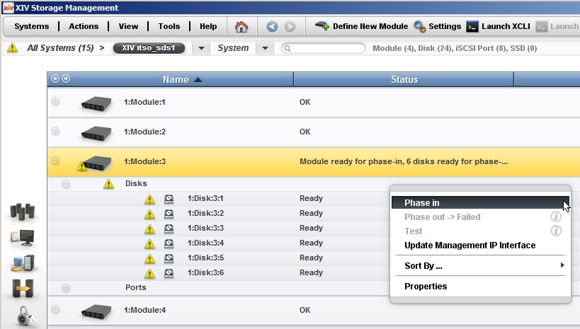
Figure 9-54 Module:3 ready for phase in
|
Note: The phase in process is run in the background (as shown in Figure 9-55 on page 295) and completes after all the data on the system is redistributed to account for the new disk. The amount of time it takes to complete the phase in process can span many hours, depending on the amount of data, number of modules and disks, and the interconnect bandwidth of the system.
|

Figure 9-55 Module:3 disks phasing in (redistributing)
When Module:3 completes the phase in process, all modules are back to OK state, as shown in Figure 9-56.

Figure 9-56 All modules in OK state, redistribution completed
At the end of the redistribution process, the system regains Full Redundancy status, as shown in Figure 9-57. This state is the wanted state and the recovery procedure is complete.

Figure 9-57 System showing Full Redundancy
9.7.2 Case 2: Module failure at VMware level (Virtual Machine is powered off)
A module failure at VMware ESXi server level occurs when a module is marked Failed in the IBM XIV Management GUI and the virtual machine shows Powered Off status when it is viewed on the VMware ESXi server.
The recovery must be performed by a user who is assigned to Operation Administrator user category on the affected IBM Spectrum Accelerate system. A user with administrative access to the VMware server that hosts the failed module is also necessary.
Typical failure scenario of a module failure at VMware level occurs
In this failure scenario, one of the IBM Spectrum Accelerate virtual machines went into a powered off state. Figure 9-58 shows a system with some kind of failure in the IBM XIV Management GUI.
Figure 9-58 System with a red triangle indicating a failure
Complete the following steps:
1. To obtain more information about the problem, select the system icon to enter the system view for the IBM Spectrum Accelerate system. Module:3 and all its disks are in failed state, as shown in Figure 9-59.

Figure 9-59 Module-3 is in failed state
2. The system events give further information about the cause for the failure. Open the Events view by selecting System → Events, as shown in Figure 9-60.
Figure 9-60 Opening the Events view
Looking at the system events (see Figure 9-61), Module:3 is listed as failed and the IBM Spectrum Accelerate system started a rebuild of the data. It is also apparent that the module lost IP connectivity, but no explanation is present. There are no other events in the IBM XIV Management GUI that explain more about the cause of the failure.

Figure 9-61 Module:3 failure events
3. Check the corresponding virtual machine on the VMware ESXi server that hosts it to gain a better understanding of the issue. Figure 9-62 shows the virtual machine in a Powered Off state.

Figure 9-62 Status of the hosting VM of module-3 is Powered Off
Recovering a failed module when the virtual machine is powered off
In this section, the process that is used to recover a failed module where the failure is at the virtual machine level on the VMware ESXi server is described. For this example, it is assumed that all of the following conditions were met:
•The virtual machine of the failed module is in the Powered Off state.
•The VMware ESXi server and virtual machine configuration is correct.
•The IBM Spectrum Accelerate system is in the Fully Redundant state.
Complete the following steps:
1. Verify that the VMware ESXi server configuration is correct. Pay special attention to ensure that the network setup is still accurate, meaning that vSwitches and port groups are present and functioning, as shown in Figure 9-63.

Figure 9-63 VMware ESXi server network configuration
2. After the server and network components are verified, power on the virtual machine by right-clicking the virtual machine in the VMware vSphere client and selecting Power → Power On, as shown in Figure 9-64.

Figure 9-64 Powering on the virtual machine
3. Allow the virtual machine to be powered on and time elapse for the start process to complete. An example of a powered on virtual machine is shown in Figure 9-65.

Figure 9-65 Virtual machine is powered on
|
Tip: System recovery actions can be completed only by an IBM Spectrum Accelerate system user who is a member of the Operations Administrator user category. Ensure that there is access to the IBM XIV Management GUI with a user of this category.
|
4. Open the IBM Spectrum Accelerate system’s System View in the IBM XIV Management GUI and right-click the failed module. Select Test (as shown in Figure 9-66) to test the module.
Figure 9-66 Start testing the module after powering on the virtual machine
5. Select OK in the Command Completed Successfully window. The module in the IBM XIV Management GUI system view changes to Module Initializing, as shown in Figure 9-67. This status indicates that the module entered Initializing mode.

Figure 9-67 Module state changes from failed to initializing
6. Soon after the testing process begins, the module state changes from Failed to Initializing and the red triangle turns yellow, as shown in Figure 9-68.
Figure 9-68 Module in initializing state
|
Note: The initialization process can take a long time to complete as many diagnostic tests are run on the component that is being tested.
|
7. When the initialization process completes, the module state changes to Ready. When the module is in a Ready state, right-click the module and select Phase in, as shown in Figure 9-69.
Figure 9-69 Module:3 ready for phase in
|
Note: The phase in process is run in the background and completes after all the data on the system is redistributed to account for the new disk (see Figure 9-70). The amount of time it takes to complete the phase in process can span many hours, depending on the amount of data, number and of disks, and the interconnect bandwidth of the system.
|
Figure 9-70 Module disks phasing in (redistributing)
8. After the Module:3 phase is completed, all modules return to an OK state, as shown in Figure 9-71.
Figure 9-71 All modules in OK state, redistribution completed
At the end of the redistribution process, the system shows Full Redundancy as its status, as shown in Figure 9-72. This is the wanted system state and the recovery procedure complete.
Figure 9-72 Back to Full Redundancy
Figure 9-73 shows the events that give a good overview of the actions that were taken during the recovery procedure, including time stamps.

Figure 9-73 Events generated during recovery procedure
9.7.3 Case 3: Module failure requiring software replacement
There can be instances in which a module is failed at the IBM Spectrum Accelerate system level and the virtual machine is not present on the VMware ESXi server. This issue can occur can be because the virtual machine was accidentally deleted. A software replacement of the module is required before it can be brought back into the IBM Spectrum Accelerate system. In this case, a new deployment is required for the module to prepare it for recovery back into the system.
The following prerequisites must be met for a successful repair action:
•A user is assigned to the Operations Administrator user category on the IBM Spectrum Accelerate system.
•A user with administrative access to the VMware ESXi server that hosts the failed module is available.
•The IBM Spectrum Accelerate deployment kit that is used to deploy the IBM Spectrum Accelerate system is available.
•The deployment configuration XML file that is used for deploying the system is available.
Typical failure scenario for a module requiring software replacement
This scenario involves one of the IBM Spectrum Accelerate virtual machines being accidentally deleted. To resolve this problem, complete the following steps:
1. Connect to the IBM Spectrum Accelerate system with a user that is a member of the Operations Administrator user category. Click the IBM Spectrum Accelerate system to enter the system view and see that a module is marked as failed.
2. Browse to the Events view to see the event log (see Figure 9-74). Event logs show the module failure and system data rebuild and redistribution.

Figure 9-74 Events posted upon module failure
3. Connect to the VMware ESXi server that hosts the IBM Spectrum Accelerate system virtual machine that corresponds to the failed module. There is no virtual machine present on the VMware ESXi server, which indicates accidental deletion.
Recovering a module by using module software replacement
Before the module is replaced, the prerequisites must be met:
•The virtual machine of the failed module is not present on the VMware ESXi server.
•The IBM Spectrum Accelerate System is in a fully redundant state.
Complete the following steps before the module is replaced:
1. Connect to the IBM Spectrum Accelerate system by using the IBM XIV Management GUI. Select Tools → XCLI to open an XCLI terminal.
2. Ensure that the system did not detect a MEDIUM_ERROR_NOT_RECOVERED event by using the IBM XIV Management XCLI, as shown in Example 9-32. This event indicates that there was a medium error detected during rebuild. If this error is found, contact IBM Technical Support for further assistance.
|
Note: The arguments for this command require the after= value to specify a start time for the event search.
The after= value specifies current date.hour minus 8,16, 24, or 32 days. Removing a failed disk that includes the undamaged partition when the functioning disk does not include the partition prevents proper recovery and must be avoided.
|
Example 9-32 Checking the event_list
XIV ITSO_SDS2>> event_list after=2015-02-28.16 code=MEDIUM_ERROR_NOT_RECOVERED
Timestamp Severity Code User Description
XIV ITSO_SDS2>>
XIV ITSO_SDS2>>
3. Run the state_list command (as shown in Example 9-33) to determine whether the system is Fully Redundant or in a rebuild or redistribution state.
Example 9-33 Verification of no rebuild, redistribution state, or any medium error events logged
XIV itso_sds1>>state_list
Category Value
system_state on
target_state on
safe_mode no
shutdown_reason No Shutdown
off_type off
redundancy_status Redistributing
ssd_caching disabled
encryption Not Supported
XIV itso_sds1>>monitor_redist
Type Initial Capacity to Copy (GB) Capacity Remaining to Copy (GB) %done Time Started Estimated Time to Finish Time Elapsed
Redistribution 17 13 24 2015-03-09 14:25:03 0:00:54 0:00:17
XIV itso_sds1>>event_list after=2015-02-28.16 code=MEDIUM_ERROR_NOT_RECOVERED
Timestamp Severity Code User Description
4. If the system is not in a fully redundant state, run the monitor_redist command to find how long an ongoing rebuild or redistribution process takes until the system achieves Full Redundancy.
|
Note: The reported times are estimations only and might increase or decrease, depending on the workload of the system. Example 9-33 shows that 24% of the capacity to redistribute is done and the remaining time is 54 seconds; however, the process can take longer.
|
Complete the following steps to recover the module. At this stage, the IBM Spectrum Accelerate system software can be deployed to the VMware ESXi server. In this example, the Windows command line is used:
1. Set up the deployment configuration XML file for deployment of the IBM Spectrum Accelerate system software to the VMware ESXi server. The easiest method is to use the deployment configuration XML file that was used to deploy the IBM Spectrum Accelerate system and remove the server specific stanzas for all the modules, except the stanza that is being redeployed. Unlike the original VMware ESXi server stanza, the option module=”X” must be added to the stanza to tell the deployment kit which specific module is being deployed.
|
Important: Example 9-34 shows the <server> stanza for Module:1 with the option module_id="1" to define the deployment as that specific module.
|
Example 9-34 The deployment configuration XML file for Module:1
<sds_machine
data_disk="6"
enable_diagnostic_mode="no"
icn="1234567"
interconnect_mtu="9000"
memory_gb="48"
name="itso_sds1"
off_premise="no"
ssd_disks="0"
use_virtual_disks="false"
vm_gateway="10.12.101.1"
vm_netmask="255.255.254.0">
<esx_servers>
<server
module_id="1"
Data store="Enterprise_1"
hostname="10.12.102.56"
interconnect_ip_address="14.60.0.4"
interconnect_ip_netmask="255.255.255.0"
interconnect_network="Interconnect"
iscsi_network="ISCSI"
mgmt_network="Management"
password="password"
username="root"
vm_mgmt_ip_address="10.12.101.77"/>
</esx_servers>
</sds_machine>
|
Note: If a deployment configuration XML file that was exported from the IBM XIV Management GUI during system deployment is used, make sure to add the correct VMware ESXi server user name and password to the server definition.
To ensure security of the VMware ESXi servers, the VMware ESXi administrative passwords are not retained in the exported deployment configuration XML files.
If the password is not added, the deployment fails with the following error messages:
Verifying SSH credentials and connection
*** Node Verification Error *** |
2. Extract the deployment kit to a folder on the Windows workstation that is being used for the redeployment of the module.
3. Open the Windows command line on the Windows workstation. Browse to the folder that contains the extracted deployment kit and select the available options by running the xiv_sds_deployment_win.cmd file without any parameters, as shown in Example 9-35.
Example 9-35 Deployment .cmd file options
C:SDS_Deploy_Win>xiv_sds_deployment_win.cmd
Usage: windows_deploy.py [options]
Options:
-h, --help show this help message and exit
-c FILE, --config=FILE
Deploy based on the specified XML configuration file
(full path).
-f, --force Allows the deployment script to delete existing VMs
that have the same name.
-a, --add-module Add one or more virtual XIV modules (storage nodes).
Can be used only with -c|--config.
-V, --verbose Run in verbose mode. Can be used only with
-c|--config.
-v, --version Display the version number of the embedded XIV
microcode.
-n, --no-startup Deploy, but do not turn the VMs.
-b, --batch Assume 'N' on all user prompts.
4. Run the deployment process by running the xiv_sds_deployment_win.cmd with the -a and -c arguments. This command deploys the IBM Spectrum Accelerate system software in the --add-module method by using the deployment configuration XML file specified with the --config option, as shown in Example 9-36.
Example 9-36 Module deploy command
C:SDS_Deploy_Win>xiv_sds_deployment_win.cmd -a -c deploy_sds_2015-02-19.19-42-54.xml -V
2015-02-27 15:03:10: Flags:
2015-02-27 15:03:10: -c deploy_sds_2015-02-19.19-42-54.xml
2015-02-27 15:03:10: -a
2015-02-27 15:03:10: --batch
2015-02-27 15:03:10: Arguments check log file for postinstall analysis located at c:usersitsoappdatalocal empcheck_args.log
2015-02-27 15:03:10: Looking for software image and for local XIV disk
2015-02-27 15:03:10: Found local XIV storage image: xiv_local_storage.vmdk
2015-02-27 15:03:10: Found XIV software image: xiv_sw_image.vmdk
2015-02-27 15:03:10: Running RelaxNG validation on deploy_sds_2015-02-19.19-42-54.xml
2015-02-27 15:03:10: XML file deploysds.xml checked succesfully and found valid
...........
For reference, the full output of the redeployment process is shown in Example 9-37.
Example 9-37 Output messages of deployment run
.........
2015-02-27 15:03:10: SDS XML file used: C:dSDS_Deploy_Windeploysds.xml
2015-02-27 15:03:10: OVF template file used: C:SDS_Deploy_WindeploySample_RDM.ovf
2015-02-27 15:03:10: Local storage VMDK disk file used: C:SDS_Deploy_Windeployxiv_local_storage.vmdk
2015-02-27 15:03:10: XIV Software VMDK disk file used: C:SDS_Deploy_Windeployxiv_sw_image.vmdk
2015-02-27 15:03:10: **********
2015-02-27 15:03:10: Running deploy_sds with the following arguments : ['-x', 'C:\SDS_Deploy_Win\deploy
sds.xml', '-o', C:\SDS_Deploy_Win\deploy\Sample_RDM.ovf', '-b', 'C:\SDS_Deploy_Win\deploy\xiv_local_storage.vmdk', '-v', 'C:\SDS_Deploy_Win\deploy\xiv_sw_image.vmdk', '-a', '--no-vcenter', '--batch']
2015-02-27 15:03:10: Starting deploy...
2015-02-27 15:03:10: Running deployment script serially
2015-02-27 15:03:14: Using vmdk image C:SDS_Deploy_Windeployxiv_sw_image.vmdk
2015-02-27 15:03:16: Parsing deploy XML C:SDS_Deploy_Windeploysds.xml
2015-02-27 15:03:16: Verifying IP addresses validity...
2015-02-27 15:03:16: IP addresses verified successfully.
2015-02-27 15:03:16: Executing ESXi verifications before deployment
2015-02-27 15:03:16: Executing ESXi verifications before deployment
2015-02-27 15:03:16: Verifying ESXi server 10.12.102.56
*** [10.12.102.56] Verifying ESXi SSH port is opened
*** [10.12.102.56] Verifying SSH credentials and connection
*** [10.12.102.56] Verifying memory size on the ESXi host
*** [10.12.102.56] Verifying data store Enterprise_1 existence on the ESXi host
*** [10.12.102.56] Verifying data store size
*** [10.12.102.56] Verifying Networking configuration validity on ESXi servers
*** [10.12.102.56] Networking configuration verified on ESXi host
2015-02-27 15:03:22: SDS ESXi Nodes Verifications Completed Successfully
2015-02-27 15:03:22: Updating OVF new_outputs/vmdk/tmp_ovf.ovf Memory Elements
2015-02-27 15:03:22: Updating memory element: rasd:ElementName with size: 49152 MB
2015-02-27 15:03:22: Updating memory element: rasd:Reservation with size: 49152 MB
2015-02-27 15:03:22: Updating memory element: rasd:VirtualQuantity with size: 49152 MB
2015-02-27 15:03:22: Saving the updated OVF XML
2015-02-27 15:03:24: Creating direct attach disks on ESXi server 10.12.102.56: 6 data disks and 0 SSD disks
2015-02-27 15:03:36: [10.12.102.56] DIRECT ATTACH SCRIPT OUTPUT :Device mpx.vmhba32:C0:T0:L0 is of type CD-ROM - skipped
2015-02-27 15:03:36: [10.12.102.56] DIRECT ATTACH SCRIPT OUTPUT :Adding Device /vmfs/devices/disks/naa.5000c50056861af7 as DATA disk #1
2015-02-27 15:03:36: [10.12.102.56] DIRECT ATTACH SCRIPT OUTPUT :Adding Device /vmfs/devices/disks/naa.5000c50056872a47 as DATA disk #2
2015-02-27 15:03:36: [10.12.102.56] DIRECT ATTACH SCRIPT OUTPUT :Adding Device /vmfs/devices/disks/naa.5000c5005686a6c3 as DATA disk #3
2015-02-27 15:03:36: [10.12.102.56] DIRECT ATTACH SCRIPT OUTPUT :Adding Device /vmfs/devices/disks/naa.5000c50056871667 as DATA disk #4
2015-02-27 15:03:36: [10.12.102.56] DIRECT ATTACH SCRIPT OUTPUT :Adding Device /vmfs/devices/disks/naa.5000c5005687135b as DATA disk #5
2015-02-27 15:03:36: [10.12.102.56] DIRECT ATTACH SCRIPT OUTPUT :Adding Device /vmfs/devices/disks/naa.5000c5005686e2d7 as DATA disk #6
2015-02-27 15:03:36: Going to deploy VM itso_sds1_module_1
Opening OVF source: new_outputs/vmdk/tmp_ovf.ovf
Opening VI target: vi://[email protected]:443/
Deploying to VI: vi://[email protected]:443/
Transfer Completed
Completed successfully
2015-02-27 15:06:46: Deploy of All modules completed successfully!
2015-02-27 15:06:46: Adding 6 data disks and 0 ssd disks to VM itso_sds1_module_1
2015-02-27 15:07:02: Adding disks to All VMs completed successfully
2015-02-27 15:07:02: Turning on VM: 'itso_sds1_module_1' on ESXi host: '10.12.102.56'
2015-02-27 15:07:11: Module 1 started successfully
2015-02-27 15:07:11: System (non-unique) serial number: 9051093
2015-02-27 15:07:11: System's machine unique ID (UUID): dd418e4f781f4864a1c7e48188098d2d
2015-02-27 15:07:11: All Done
C:SDS_Deploy_Win>
5. Verify that the status of the virtual machine on the VMware ESXi host server is in a Power on state, as shown in Figure 9-75.

Figure 9-75 VM is back in the Power on state
6. Connect the IBM Spectrum Accelerate system by using the IBM XIV Management GUI with a user who is a member of the Operations Administrator user category.
7. Click the system to enter the System view. Right-click the failed module and select Test, as shown in Figure 9-76.

Figure 9-76 Module menu: Test
8. The IBM XIV Management GUI now displays a view as shown in Figure 9-77, which indicates that the module entered the Initializing state. During initialization, the module undergoes various tests to verify that all required components are present and ready to be used. Within a matter of minutes, the module state changes from Failed to Initializing and the red triangle turn yellow.

Figure 9-77 Module:1 in initializing state
|
Note: Allow the module to complete the testing process and have a state of Ready. This process can take time because of the various tests that are conducted on the module.
|
9. Right-click the module and select Phase in, as shown in Figure 9-78. This step is the last step of the manual recovery process.

Figure 9-78 Module:1 phase in
|
Note: The phase in process is run in the background and completes after all the data on the system is redistributed to account for the new disk. The amount of time it takes to complete the phase in process can span many hours, depending on the amount of data, number of modules and disks, and the interconnect bandwidth of the system.
|
10. The phase in process continues (see Figure 9-79) until the system reaches the Full Redundancy state.

Figure 9-79 Module disks phasing in (redistributing)
Figure 9-80 shows a typical pattern of a test and phase in of a module. There is no view of the actions taken on the VMware ESXi server because the IBM Spectrum Accelerate system has no visibility to the underlying layers.

Figure 9-80 Recovery events
9.7.4 Case 4: Module failure requiring hardware replacement
This section describes the situation in which a module is defective in such a way that a hardware replacement of the entire VMware ESXi server is necessary.
Signs that hardware replacement are necessary include that the VMware ESXi server does not power on or the system board reports a severe error or another major component, such as the disk controller is defective.
It is up to the IBM Spectrum Accelerate system administrator to decide what kind of repair action to apply. That task can include identifying the defective component and repairing it immediately or replacing the entire server. In cases where downtime is critical, the best practice is to have spare servers available to replace defective equipment quickly.
Another decision that must be made is whether to reuse the HDDs from the failed server or replace them. From an IBM Spectrum Accelerate viewpoint, both methods are valid; therefore, the decision must be based on cost, age, and wear of the old HDDs and any other procedures that might be in place.
The process to replace module hardware is essentially the same as IBM Spectrum Accelerate system software replacement, with the following exceptions:
•A replacement server must be installed and connected to the network.
•The VMware ESXi server configuration is configured for the environment.
The following prerequisites must be met to successfully repair a module:
•A user account assigned to the Operations Administrator user category on the IBM Spectrum Accelerate system is available.
•A user account with administrative access to the VMware ESXi server which hosts the IBM Spectrum Accelerate virtual machine is available.
•Replacement hardware (with or without HDDs) is available.
•Enough HDDs with the correct capacity must be installed in the replacement VMware ESXi server.
•VMWare ESXi installation media are available with a version of VMware ESXi that is at the same level as what is installed on the other VMware ESXi servers that host IBM Spectrum Accelerate virtual machines.
•Device driver files that are not part of the standard VMware ESXi installation media are available.
•Configuration setup information for Storage and Networking is available.
•The IBM Spectrum Accelerate deployment kit that is used for deploying IBM Spectrum Accelerate systems is available.
•An IBM Spectrum Accelerate system deployment configuration XML file that is used to deploy the original IBM Spectrum Accelerate system is available.
•Mechanical tools and a lifter to replace the old server and install the new one are available, if needed.
Configuration information of a module (pre-failure task)
This section describes the following information from the old (failed) server that is required to successfully install the VMware Hypervisor on a replacement:
•The virtual machine summary window provides an overview of the setup, as shown in Figure 9-81. (The networking setup that is shown is an example and does not necessarily represent best practices.)

Figure 9-81 Virtual machine summary window
•Information about the data stores, as shown in Figure 9-82.

Figure 9-82 Data store information
•Information about network adapters that are installed in the module, as shown in Figure 9-83.

Figure 9-83 Network adapters installed in module
•Information about the networking setup of module, as shown in Figure 9-84.
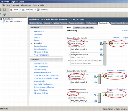
Figure 9-84 Networking configuration
Complete the following steps:
1. Set the MTU to 9000 for 10 GbE ports for the ports that are being dedicated to the IBM Spectrum Accelerate interconnection ports, as shown in Figure 9-85.

Figure 9-85 Setting MTU to 9000 for 10 GbE ports
2. Set the MTU to 9000 for 10 GbE ports for the ports that are being dedicated to the IBM Spectrum Accelerate iSCSI connectivity ports, as shown in Figure 9-86.

Figure 9-86 Setting MTU for iSCSI ports
Typical failure scenario with module hardware replacement
In the scenario that is described in this section, a module failed with a severe hardware error and the underlying VMware ESXi server must be replaced.
The IBM XIV management GUI shows the system with a yellow or a red triangle and that the system is in a rebuild state, as shown in Figure 9-87.

Figure 9-87 System reporting a severe error and doing a rebuild
To identify the cause of the problem, click the system to enter the System view. This view shows that Module:1 failed, as shown in Figure 9-88. The rebuild completed successfully and the system is fully redundant again. Module:1 is still visible, despite that it is in fact powered off.

Figure 9-88 Module:1 failed, but system is fully redundant
The VMware vSphere client has lost the connection to the VMware ESXi server because of a hardware failure, as shown in Figure 9-89.

Figure 9-89 VMware Client connection loss
Trying to reconnect the VMware vSphere client fails because the server is not power on, as shown in Figure 9-90.

Figure 9-90 Not possible to reconnect to module
Recovering server hardware through hardware replacement
The following procedure describes the replacement of a VMware ESXi server that hosted an IBM Spectrum Accelerate system. This process assumes that the VMware ESXi installation is done from a USB flash drive. Also, the HDDs from the failed server are reused.
Important pre-checks before VMware ESXi server hardware replacement
Complete the following steps to verify that the IBM Spectrum Accelerate system completed the rebuild process and that no unrecoverable media errors were detected:
1. Connect to the IBM Spectrum Accelerate system by using the IBM XIV Management GUI.
2. Select Tools → XCLI to open an IBM XIV Management XCLI terminal.
3. Ensure that the system has not detected a MEDIUM_ERROR_NOT_RECOVERED event by using the IBM XIV Management XCLI, as shown in Example 9-38. This event indicates that there was a medium error detected during rebuild. If this error is found, contact IBM Technical Support for further assistance.
|
Note: The arguments for this command require the after= value to specify a start time for the event search.
The after= value specifies current date.hour minus 8,16, 24, or 32 days. Removing a failed disk that includes the undamaged data when the functioning disk does not include the data prevents proper recovery and must be avoided.
|
Example 9-38 Checking the event_list
XIV ITSO_SDS2>> event_list after=2015-02-28.16 code=MEDIUM_ERROR_NOT_RECOVERED
Timestamp Severity Code User Description
XIV ITSO_SDS2>>
XIV ITSO_SDS2>>
4. Run the state_list command (as shown in Example 9-39) to determine whether the system is Fully Redundant or in a rebuild or redistribution state.
5. If the system is not in a fully redundant state, run the monitor_redist command to find how long an ongoing rebuild or redistribution process takes until the system achieves Full Redundancy.
|
Note: The reported times are estimations only and might increase or decrease, depending on the workload of the system. Example 9-39 shows that 24% of the capacity to redistribute is done and the remaining time is 54 seconds, but the process can take longer.
|
Example 9-39 Verification of no rebuild, redistribution state, or any medium error events logged
XIV itso_sds1>>state_list
Category Value
system_state on
target_state on
safe_mode no
shutdown_reason No Shutdown
off_type off
redundancy_status Redistributing
ssd_caching disabled
encryption Not Supported
XIV itso_sds1>>monitor_redist
Type Initial Capacity to Copy (GB) Capacity Remaining to Copy (GB) %done Time Started Estimated Time to Finish Time Elapsed
Redistribution 17 13 24 2015-03-09 14:25:03 0:00:54 0:00:17
XIV itso_sds1>>event_list after=2015-02-28.16 code=MEDIUM_ERROR_NOT_RECOVERED
Timestamp Severity Code User Description
VMware ESXi server hardware replacement: Installing Module Exchange and VMware ESXi
Complete the following steps:
1. Remove the failed and powered-off VMware ESXi server mechanically from the rack.
2. If the old HDDs are being reused, remove each disk from the failed server.
3. If the old HDDs are being reused, insert each disk into the new server (slot position is not important).
|
Note: The disk that holds the old data store is not inserted at this stage to ensure a clean installation of the VMware ESXi to a new disk. The disk with the old data store was inserted into its slot after customization was finished and before the VMware ESXi was restarted.
|
4. Write down the disk slot, serial number, and WWN of each disk in a table as described in Table 2-1 on page 19.
5. Insert the new server into the rack.
6. Insert a USB stick with the required VMware Hypervisor installer files.
7. Connect the power and data cables to the new module.
8. When starting the system, press the hot key to start from the USB.
9. The VMware installer installs the Hypervisor on the module and requests the following user input:
a. Select a disk with a VMFS partition for Installation (preferably the disk in slot 0).
b. Enter a root password twice.
The installer scans the hardware of the system and installs VMware ESXi on the selected disk.
After the installation process is completed, VMware ESXi restarts.
After entering the root password, the System Customization menu is displayed.
c. Select Configure Management Network, IP Configuration, and then select Set static IP address.
d. Enter the VMware ESXi server Management IP Address, Subnet Mask, and default Gateway IP Address. Select OK.
e. Select DNS Configuration.
f. Enter Primary / Alternate DNS Server IP, and Hostname =localhost or 127.0.0.1. Select OK.
g. Select Network Adapters.
h. Select Device with Status Connected for the VMware ESXi management network connection and click OK.
i. As network setup is complete, press ESC to leave Configure Management Network.
j. Optionally, test the configuration by selecting Test Management Network.
k. If network test was successful, select Restart Management Network.
Management network is restarted and changes are applied.
l. Select Troubleshooting Options from the Customization menu with the following settings:
i. Keep Enable VMware ESXi Shell.
ii. Select Enable SSH.
If the VMware ESXi server module has other adapters (such as a 10 GbE adapter), the appropriate device drivers must be installed. Because the VMware ESXi server is now available on the management network, the driver installation can be done remotely by using an SSH tool, such as PuTTY.
10. Insert the disk with that was left out in step 3, with the old data store.
11. After installing all required device drivers, restart the VMware ESXi server.
VMware ESXi server hardware replacement: VMware ESXi setup
Complete the following steps:
1. When the VMware ESXi server completes the start process, connect as an administrative user by using the VMware vSphere client.
2. After connecting the VMware vSphere client, the data store view shows two data stores, as shown in Figure 9-91. It is apparent that both of the old disks were reinstalled into the replacement server:
– Enterprise_1 is the data store from the old VMware ESXi server before the module replacement.
– datastore1 is the data store from the new VMware ESXi installation, which is the correct data store.

Figure 9-91 Two data stores shown upon restart

Figure 9-92 Deleting old data store
4. Confirm that the data store was deleted and verify that the old Enterprise_1 data store is no longer present and the new datastore1 remains. Rename datastore1 to be compliant with your environment, as shown in Figure 9-93. The data store name must comply with the data store that is defined in the deployment configuration XML file for the module being replaced.

Figure 9-93 Rename new data store
Figure 9-94 shows how to enter the new data store name.

Figure 9-94 datastore1 renamed to Enterprise_1
Figure 9-95 shows the disk holding data store Enterprise_1 along with seven other data disks and a CD-ROM device.

Figure 9-95 Storage devices installed in module
5. Configure the VMware ESXi network and virtual network devices so that they are consistent with the environment on which the server is being deployed. In our example, only the VMware ESXi management network is defined, as shown in Figure 9-96.

Figure 9-96 VMware ESXi management network
6. Start with renaming the Management Network port group from VM Network to the name of the management network that is defined in the deployment configuration XML file. Select Properties of vSwitch0. Then, select VM Network and click Edit. A window opens in which the name can be changed, as shown in Figure 9-97.

Figure 9-97 Renaming the network
7. Two more virtual switches must be configured: one for the module-to-module interconnect network and another for the iSCSI connection to external hosts. In this example, two separate 10 GbE adapters are used. Select Add Networking from the Networking window, as shown in Figure 9-98 on page 325.

Figure 9-98 Starting the Network set up wizard

Figure 9-99 Create a Virtual Machine connection
9. In the Network Access window, select the adapter to be used for the new vSwitch. In this example, it is a 10 GbE QLogic adapter vmnic5, as shown in Figure 9-100 on page 326. A value of 10000 Full in the column Speed indicates that the adapter is up and running.
|
Note: If the network device was not active, the Speed column shows Down as can be seen for vmnic0, vmnic1, and vmnic2.
|

Figure 9-100 Selecting an active adapter
10. In the Connections Settings window, enter a name for the new network that the port group name assigned to the iSCSI connectivity in the IBM Spectrum Accelerate deployment configuration XML file and leave the optional VLAN ID at None, as shown in Figure 9-101.

Figure 9-101 Label for the new network
11. Select the Summary tab and click Finish to finalize the virtual switch configuration.
12. Change the MTU for the newly generated network to 9000 to match the value in the deployment configuration XML file that is used later. Select Properties of vSwitch2. Then, select vSwitch and click Edit to see the window that is shown in Figure 9-102. Change the MTU on the General tab from 1500 to 9000.

Figure 9-102 Maximum Transmission Unit
13. After setting up the ISCSI network, repeat steps 8 - 14 to complete the same setup for the Interconnect network. Always remember to use the same names and values that are in the deployment configuration XML file.
14. After completing the networking setup, Figure 9-103 shows the final Networking Configuration. It consists of three vSwitches: one for Management at 1 GbE, one for Interconnect at 10 GbE, and one for iSCSI at 10 GbE speed.

Figure 9-103 Networking configuration example
15. To conclude the networking setup, select the Configuration tab then Network Adapters, as shown in Figure 9-104. The tab provides the same information as shown in Figure 9-103, but from the adapter’s viewpoint.

Figure 9-104 Networking Adapters overview
VMware ESXi server hardware replacement Step 3: Module deployment
The IBM Spectrum Accelerate system software can be deployed to the configured VMware ESXi server by using the IBM Spectrum Accelerate Windows deployment kit. Complete the following steps:
1. Set up the deployment configuration XML file. The easiest method to configure the file is to take the deployment configuration XML file that was used for deploying the IBM Spectrum Accelerate system and removing all <server> stanzas, except for the module that is being replaced. That <server> stanza must contain the parameter module=”X” where X is the module number that is being deployed. Example 9-40 shows adding module_id="1" to deploy a replacement for the failed Module:1 at the IBM Spectrum Accelerate system layer.
Example 9-40 Deployment configuration XML file for Module:1
<sds_machine
data_disk="6"
enable_diagnostic_mode=”yes"
icn="1234567"
interconnect_mtu="9000"
memory_gb="48"
name="itso_sds1"
off_premise="no"
ssd_disks="0"
use_virtual_disks="false"
vm_gateway="10.12.101.1"
vm_netmask="255.255.254.0">
<esx_servers>
<server
module_id="1"
Data store="Enterprise_1"
hostname="10.12.102.56"
interconnect_ip_address="14.60.0.4"
interconnect_ip_netmask="255.255.255.0"
interconnect_network="Interconnect"
iscsi_network="ISCSI"
mgmt_network="Management"
password="password"
username="root"
vm_mgmt_ip_address="10.12.101.77"/>
</esx_servers>
</sds_machine>
|
Note: If a deployment configuration XML file that was exported from the IBM XIV Management GUI during system deployment is used, make sure to add the correct VMware ESXi server user name and password to the server definition.
To ensure security of the VMware ESXi servers, VMware ESXi administrative passwords are not retained in exported deployment configuration XML files.
If the password is not added, the deployment fails with the error messages:
Verifying SSH credentials and connection
*** Node Verification Error *** |
2. After setting up the deployment configuration XML file, extract the deployment kit archive to a location on a Windows workstation.
3. Open the Windows command-line and browse to the folder that contains the extracted deployment files. Check the available options of using the deployment kit by running the xiv_sds_deployment_win.cmd file without any parameters, as shown in Example 9-41.
Example 9-41 Deployment .cmd file options
C:SDS_Deploy_Win>xiv_sds_deployment_win.cmd
Usage: windows_deploy.py [options]
Options:
-h, --help show this help message and exit
-c FILE, --config=FILE
Deploy based on the specified XML configuration file
(full path).
-f, --force Allows the deployment script to delete existing VMs
that have the same name.
-a, --add-module Add one or more virtual XIV modules (storage nodes).
Can be used only with -c|--config.
-V, --verbose Run in verbose mode. Can be used only with
-c|--config.
-v, --version Display the version number of the embedded XIV
microcode.
-n, --no-startup Deploy, but do not turn the VMs.
-b, --batch Assume 'N' on all user prompts.
4. Run the deployment process by running the xiv_sds_deployment_win.cmd command with the -a and -c arguments. This command deploys the IBM Spectrum Accelerate system software in the --add-module method by using the deployment configuration XML that is file specified with the --config option, as shown in Example 9-42.
Example 9-42 Module deploy command
C:SDS_Deploy_Win>xiv_sds_deployment_win.cmd -a -c deploy_itso_sds1_module_1_20150306.xml -V
2015-03-06 15:54:24: Flags:
2015-03-06 15:54:24: -c deploy_itso_sds1_module_1_20150306.xml
2015-03-06 15:54:24: -a
2015-03-06 15:54:24: --batch
2015-03-06 15:54:24: Arguments check log file for postinstall analysis located at c:usersddadappdatalocal empcheck_args.log
2015-03-06 15:54:24: Looking for software image and for local XIV disk
2015-03-06 15:54:24: Found local XIV storage image: xiv_local_storage.vmdk
2015-03-06 15:54:24: Found XIV software image: xiv_sw_image.vmdk
2015-03-06 15:54:24: Running RelaxNG validation on deploy_itso_sds1_module_1_20150306.xml
2015-03-06 15:54:24: XML file deploysds.xml checked succesfully and found valid
2015-03-06 15:54:24: SDS XML file used: C:SDS_Deploy_Windeploysds.xml
2015-03-06 15:54:24: OVF template file used: C:SDS_Deploy_WindeploySample_RDM.ovf
2015-03-06 15:54:24: Local storage VMDK disk file used: C:SDS_Deploy_Windeployxiv_local_storage.vmdk
2015-03-06 15:54:24: XIV Software VMDK disk file used: C:SDS_Deploy_Windeployxiv_sw_image.vmdk
2015-03-06 15:54:24: **********
.........
For reference, the rest of the command output is shown in Example 9-43.
Example 9-43 Output messages of deployment run
.........
2015-03-06 15:54:24: Running deploy_sds with the following arguments : ['-x', 'C:\SDS_Deploy_Win\deploy\sds.xml', '-o', 'C:\SDS_Deploy_Win\deploy\Sample_R
DM.ovf', '-b', 'C:\SDS_Deploy_Win\deploy\xiv_local_storage.vmdk', '-v', 'C:\SDS_Deploy_Win\deploy\xiv_sw_image.vmdk', '-f', '-a', '--no-vcenter', '--batch
2015-03-06 15:54:24: Starting deploy...
2015-03-06 15:54:24: Running deployment script serially
2015-03-06 15:54:46: Using vmdk image C:SDS_Deploy_Windeployxiv_sw_image.vmdk
2015-03-06 15:54:48: Parsing deploy XML C:SDS_Deploy_Windeploysds.xml
2015-03-06 15:54:48: Verifying IP addresses validity...
2015-03-06 15:54:48: IP addresses verified successfully.
2015-03-06 15:54:48: Executing ESXi verifications before deployment
2015-03-06 15:54:48: Executing ESXi verifications before deployment
2015-03-06 15:54:48: Verifying ESXi server 9.xx.yy9.56
*** [9.xx.yy9.56] Verifying ESXi SSH port is opened
*** [9.xx.yy9.56] Verifying SSH credentials and connection
*** [9.xx.yy9.56] Verifying memory size on the ESXi host
*** [9.xx.yy9.56] Verifying data store Enterprise_1 existence on the ESXi host
*** [9.xx.yy9.56] Verifying data store size
*** [9.xx.yy9.56] Verifying Networking configuration validity on ESXi servers
*** [9.xx.yy9.56] Networking configuration verified on ESXi host
2015-03-06 15:54:55: SDS ESXi Nodes Verifications Completed Successfully
2015-03-06 15:54:55: Updating OVF new_outputs/vmdk/tmp_ovf.ovf Memory Elements
2015-03-06 15:54:55: Updating memory element: rasd:ElementName with size: 49152 MB
2015-03-06 15:54:55: Updating memory element: rasd:Reservation with size: 49152 MB
2015-03-06 15:54:55: Updating memory element: rasd:VirtualQuantity with size: 49152 MB
2015-03-06 15:54:55: Saving the updated OVF XML
2015-03-06 15:54:58: VM itso_sds1_module_1 already exists - deleting it
2015-03-06 15:54:58: Removing VM itso_sds1_module_1
2015-03-06 15:55:01: Creating direct attach disks on ESXi server 9.xx.yy9.56: 6 data disks and 0 SSD disks
2015-03-06 15:55:14: [9.xx.yy9.56] DIRECT ATTACH SCRIPT OUTPUT :Device mpx.vmhba32:C0:T0:L0 is of type CD-ROM - skipped
2015-03-06 15:55:14: [9.xx.yy9.56] DIRECT ATTACH SCRIPT OUTPUT :Adding Device /vmfs/devices/disks/naa.5000c50056861af7 as DATA disk #1
2015-03-06 15:55:14: [9.xx.yy9.56] DIRECT ATTACH SCRIPT OUTPUT :Adding Device /vmfs/devices/disks/naa.5000c5005686a6c3 as DATA disk #2
2015-03-06 15:55:14: [9.xx.yy9.56] DIRECT ATTACH SCRIPT OUTPUT :Adding Device /vmfs/devices/disks/naa.5000c50056871667 as DATA disk #3
2015-03-06 15:55:14: [9.xx.yy9.56] DIRECT ATTACH SCRIPT OUTPUT :Adding Device /vmfs/devices/disks/naa.5000c5005687135b as DATA disk #4
2015-03-06 15:55:14: [9.xx.yy9.56] DIRECT ATTACH SCRIPT OUTPUT :Adding Device /vmfs/devices/disks/naa.5000c5005686e2d7 as DATA disk #5
2015-03-06 15:55:14: [9.xx.yy9.56] DIRECT ATTACH SCRIPT OUTPUT :Adding Device /vmfs/devices/disks/naa.5000c50056870fb3 as DATA disk #6
2015-03-06 15:55:14: Going to deploy VM itso_sds1_module_1
Opening OVF source: new_outputs/vmdk/tmp_ovf.ovf
Opening VI target: vi://[email protected]:443/
Deploying to VI: vi://[email protected]:443/
^C2015-03-06 15:57:33: Error:
Ctr-C detected, terminating
2015-03-06 15:57:33: Error: An unexpected error has occurred during deployment
2015-03-06 15:57:33:
2015-03-06 15:57:33: The Spectrum Accelerate deployment has failed.
2015-03-06 15:57:34:
2015-03-06 15:57:34: For a possible solution:
2015-03-06 15:57:34:
2015-03-06 15:57:34: * Search any web search engine to find a relevant IBM KB article
2015-03-06 15:57:34: * Look for an expert solution in dW Answers (developer.ibm.com/answers)
2015-03-06 15:57:34: * Open a service request ticket for IBM Support (ibm.biz/BdEkWE)
2015-03-06 15:57:34:
Terminate batch job (Y/N)? y
C:SDS_Deploy_Win>xiv_sds_deployment_win.cmd -a -c deploy_itso_sds1_module_1_20150306y.xml -V -f
2015-03-06 16:11:48: Flags:
2015-03-06 16:11:48: -c deploy_itso_sds1_module_1_20150306y.xml
2015-03-06 16:11:48: -a
2015-03-06 16:11:48: --force
2015-03-06 16:11:48: --batch
2015-03-06 16:11:48: Arguments check log file for postinstall analysis located at c:usersddadappdatalocal empcheck_args.log
2015-03-06 16:11:48: Looking for software image and for local XIV disk
2015-03-06 16:11:48: Found local XIV storage image: xiv_local_storage.vmdk
2015-03-06 16:11:48: Found XIV software image: xiv_sw_image.vmdk
2015-03-06 16:11:48: Running RelaxNG validation on deploy_itso_sds1_module_1_20150306y.xml
2015-03-06 16:11:48: XML file deploysds.xml checked succesfully and found valid
2015-03-06 16:11:48: SDS XML file used: C:SDS_Deploy_Windeploysds.xml
2015-03-06 16:11:48: OVF template file used: C:SDS_Deploy_WindeploySample_RDM.ovf
2015-03-06 16:11:48: Local storage VMDK disk file used: C:SDS_Deploy_Windeployxiv_local_storage.vmdk
2015-03-06 16:11:48: XIV Software VMDK disk file used: C:SDS_Deploy_Windeployxiv_sw_image.vmdk
2015-03-06 16:11:48: **********
2015-03-06 16:11:48: Running deploy_sds with the following arguments : ['-x', 'C:\SDS_Deploy_Win\deploy\sds.xml', '-o', 'C:\SDS_Deploy_Win\deploy\Sample_R
DM.ovf', '-b', 'C:\SDS_Deploy_Win\deploy\xiv_local_storage.vmdk', '-v', 'C:\SDS_Deploy_Win\deploy\xiv_sw_image.vmdk', '-f', '-a', '--no-vcenter', '--batch
2015-03-06 16:11:48: Starting deploy...
2015-03-06 16:11:48: Running deployment script serially
2015-03-06 16:13:41: Using vmdk image C:SDS_Deploy_Windeployxiv_sw_image.vmdk
2015-03-06 16:13:56: Parsing deploy XML C:SDS_Deploy_Windeploysds.xml
2015-03-06 16:13:56: Verifying IP addresses validity...
2015-03-06 16:13:56: IP addresses verified successfully.
2015-03-06 16:13:56: Executing ESXi verifications before deployment
2015-03-06 16:13:56: Executing ESXi verifications before deployment
2015-03-06 16:13:56: Verifying ESXi server 9.xx.yy9.56
*** [9.xx.yy9.56] Verifying ESXi SSH port is opened
*** [9.xx.yy9.56] Verifying SSH credentials and connection
*** [9.xx.yy9.56] Verifying memory size on the ESXi host
*** [9.xx.yy9.56] Verifying data store Enterprise_1 existence on the ESXi host
*** [9.xx.yy9.56] Verifying data store size
*** [9.xx.yy9.56] Verifying Networking configuration validity on ESXi servers
*** [9.xx.yy9.56] Networking configuration verified on ESXi host
2015-03-06 16:14:02: SDS ESXi Nodes Verifications Completed Successfully
2015-03-06 16:14:02: Updating OVF new_outputs/vmdk/tmp_ovf.ovf Memory Elements
2015-03-06 16:14:03: Updating memory element: rasd:ElementName with size: 49152 MB
2015-03-06 16:14:03: Updating memory element: rasd:Reservation with size: 49152 MB
2015-03-06 16:14:03: Updating memory element: rasd:VirtualQuantity with size: 49152 MB
2015-03-06 16:14:03: Saving the updated OVF XML
2015-03-06 16:14:04: Creating direct attach disks on ESXi server 9.xx.yy9.56: 6 data disks and 0 SSD disks
2015-03-06 16:14:18: [9.xx.yy9.56] DIRECT ATTACH SCRIPT OUTPUT :Device mpx.vmhba32:C0:T0:L0 is of type CD-ROM - skipped
2015-03-06 16:14:18: [9.xx.yy9.56] DIRECT ATTACH SCRIPT OUTPUT :Adding Device /vmfs/devices/disks/naa.5000c50056861af7 as DATA disk #1
2015-03-06 16:14:18: [9.xx.yy9.56] DIRECT ATTACH SCRIPT OUTPUT :Adding Device /vmfs/devices/disks/naa.5000c5005686a6c3 as DATA disk #2
2015-03-06 16:14:18: [9.xx.yy9.56] DIRECT ATTACH SCRIPT OUTPUT :Adding Device /vmfs/devices/disks/naa.5000c50056871667 as DATA disk #3
2015-03-06 16:14:18: [9.xx.yy9.56] DIRECT ATTACH SCRIPT OUTPUT :Adding Device /vmfs/devices/disks/naa.5000c5005687135b as DATA disk #4
2015-03-06 16:14:18: [9.xx.yy9.56] DIRECT ATTACH SCRIPT OUTPUT :Adding Device /vmfs/devices/disks/naa.5000c5005686e2d7 as DATA disk #5
2015-03-06 16:14:18: [9.xx.yy9.56] DIRECT ATTACH SCRIPT OUTPUT :Adding Device /vmfs/devices/disks/naa.5000c50056870fb3 as DATA disk #6
2015-03-06 16:14:18: Going to deploy VM itso_sds1_module_1
Opening OVF source: new_outputs/vmdk/tmp_ovf.ovf
Opening VI target: vi://[email protected]:443/
Deploying to VI: vi://[email protected]:443/
Transfer Completed
Completed successfully
2015-03-06 16:18:12: Deploy of All modules completed successfully!
2015-03-06 16:18:12: Adding 6 data disks and 0 ssd disks to VM itso_sds1_module_1
2015-03-06 16:18:28: Adding disks to All VMs completed successfully
2015-03-06 16:18:28: Turning on VM: 'itso_sds1_module_1' on ESXi host: '9.xx.yy9.56'
2015-03-06 16:18:38: Module 1 started successfully
2015-03-06 16:18:38: Running diagnostice mode analysis, please wait for result.
2015-03-06 16:18:38: Waiting for diagnostic results from http://9.xx.zz8.77:8080/GetDiagnostic
2015-03-06 16:19:29: Please allow up to 20 minutes for system diagnostics. 0.85 minutes elapsed.
2015-03-06 16:20:00: Please allow up to 20 minutes for system diagnostics. 1.37 minutes elapsed.
2015-03-06 16:20:31: Please allow up to 20 minutes for system diagnostics. 1.88 minutes elapsed.
2015-03-06 16:20:31: module-1(14.60.0.4): 03-06 20:26:31 Disk_Bandwidth [WARNING] 6 Disks 6 Bad Disks Avg disk speed: 90.800000 Lowest Disk Speed: 83.500000 A
vg-Lowest: 7.300000
2015-03-06 16:20:31: module-1(14.60.0.4): 03-06 20:26:31 Disk_Bandwidth [WARNING] Disk write speed is below the minimal threshold. This might result in data loss if power supply is disconnected within 39.52 seconds of an unplanned shutdown.
2015-03-06 16:20:31: Diagnostics results written in DiagLog_itso_sds1_20150306-162031.
2015-03-06 16:20:31: WARNING: System diagnostics has raised warning(s). Please review the messages above and consider implications before putting the system into use.
2015-03-06 16:20:31: Restarting VM: 'itso_sds1_module_1' on ESXi host: '9.xx.yy9.56'
2015-03-06 16:20:37: Module 1 restarted successfully
2015-03-06 16:20:37:System (non-unique) serial number: 9004779
2015-03-06 16:20:37:System unique ID (UUID): 9be5a6ee0c154afe8911a32af93e5348
2015-03-06 16:20:37: All Done
|
Note: According to the last message lines, the deployment kit assigned a new non-unique serial number and unique serial number (UUID) to the system.
This message can be disregarded as the cluster assigns the original system serial and UUID number to the module.
|
During deployment, the open virtualization format (.ovf) file is copied to the VMware ESXi server, as shown in Figure 9-105.

Figure 9-105 OVF file deployment to new module
The virtual machine is further reconfigured; for example, by setting up the RDMs. The virtual machine then is powered on, as shown in Figure 9-106.

Figure 9-106 Messages posted during the virtual machine deployment process
5. To find which of the eight installed disks are set up by the deployment script as RDM drives for use by IBM Spectrum Accelerate, review the script output messages, as shown in Example 9-44.
Example 9-44 Output of the deployment script showing the installed RDM data disks:
2015-03-06 15:55:14: [9.xx.yy9.56] DIRECT ATTACH SCRIPT OUTPUT :Adding Device /vmfs/devices/disks/naa.5000c50056861af7 as DATA disk #1
2015-03-06 15:55:14: [9.xx.yy9.56] DIRECT ATTACH SCRIPT OUTPUT :Adding Device /vmfs/devices/disks/naa.5000c5005686a6c3 as DATA disk #2
2015-03-06 15:55:14: [9.xx.yy9.56] DIRECT ATTACH SCRIPT OUTPUT :Adding Device /vmfs/devices/disks/naa.5000c50056871667 as DATA disk #3
2015-03-06 15:55:14: [9.xx.yy9.56] DIRECT ATTACH SCRIPT OUTPUT :Adding Device /vmfs/devices/disks/naa.5000c5005687135b as DATA disk #4
2015-03-06 15:55:14: [9.xx.yy9.56] DIRECT ATTACH SCRIPT OUTPUT :Adding Device /vmfs/devices/disks/naa.5000c5005686e2d7 as DATA disk #5
2015-03-06 15:55:14: [9.xx.yy9.56] DIRECT ATTACH SCRIPT OUTPUT :Adding Device /vmfs/devices/disks/naa.5000c50056870fb3 as DATA disk #6
6. Comparing the list of disks in Example 9-44 with the disks that are listed by the clicking Configuration → Storage → Devices (see Figure 9-107), the disk that ends in “2a47” that contains the data store “1d0b” is not used as an RDM disk.

Figure 9-107 List of storage devices in virtual machine data store
7. Verify that the virtual machine is in Power on state when the deployment process completes, as shown in Figure 9-108.

Figure 9-108 Verify the virtual machine is Powered on
VMware ESXi server hardware replacement: IBM Spectrum Accelerate Module test and phase in
To complete the repair, the replacement module must be recovered at the IBM Spectrum Accelerate level. Complete the following steps:
1. Verify that the status of the virtual machine on the VMware ESXi server is in a Power on state, as shown in Figure 9-109.

Figure 9-109 Verify that the virtual machine is back in the Power on state
2. Connect the IBM Spectrum Accelerate system by using the IBM XIV Management GUI with a user who is a member of the Operations Administrator user category.
3. Select the system to enter the System view. Right-click the failed module and select Test, as shown in Figure 9-110.

Figure 9-110 Module menu: Test
4. The IBM XIV Management GUI now displays a view that indicates that the module entered the Initializing state. During initialization, the module undergoes various tests to verify that all required components are present and ready to be used. Within a matter of minutes, the module state changes from Failed to Initializing and the red triangle turn yellow, as shown in Figure 9-111 on page 338.

Figure 9-111 Module:1 in initializing state
|
Note: Allow the module to complete the testing process and change into a state of Ready. This process can take time because of the various tests that are conducted on the module.
|
5. Right-click the module and select Phase in, as shown in Figure 9-112. This step is the last step of the manual recovery actions.

Figure 9-112 Module:1 phase in
|
Note: The phase in process is run in the background and completes after all the data on the system is redistributed to account for the new disk. The amount of time it takes to complete the phase in process can span many hours, depending on the amount of data, number of and disks, and the interconnect bandwidth of the system.
|
6. The phase in process continues (as shown in Figure 9-113) until the system reaches the Full Redundancy state.

Figure 9-113 Module disks phasing in (redistributing)
Figure 9-114 shows a typical pattern of a test and phase in of a module. There is no view of the actions that were taken on the VMware ESXi host server because the IBM Spectrum Accelerate system has no visibility of the underlying layers.

Figure 9-114 Phase in process steps
9.7.5 Repairing module software or hardware with IBM XIV Management GUI
Instead of using the Windows command prompt or Linux shell mode for redeploying a failed module, the IBM XIV Management GUI on a Windows workstation can be used.
The following prerequisites must be met to complete module hardware or software repair by using the IBM XIV Management GUI:
•Network connectivity to the IBM Spectrum Accelerate system is available.
•An IBM Spectrum Accelerate user who is a member of the Operations Administrator user category is available.
•A VMware ESXi user account with administrative access is available.
•Verify that the IBM Spectrum Accelerate virtual machine is in a powered off state.
•the Windows IBM Spectrum Accelerate deployment kit can be accessed.
•A deployment configuration XML file that was used when the system was deployed is available.
•The IBM Spectrum Accelerate system must be in a Full Redundancy status.
To repair the failed module, complete the following steps:
1. Verify that the VMware ESXi server and IBM Spectrum Accelerate virtual machine are configured similarly to the other servers in the cluster. Also, verify that the IBM Spectrum Accelerate virtual machine is in the Powered Off state, as shown in Figure 9-115.

Figure 9-115 Module needs to be pre-configured

Figure 9-116 Define New Module option
3. From the General tab of the Deployment window, select Browse to specify the path to the Deployment Execution file, as shown in Figure 9-117.

Figure 9-117 Browse for deployment executable file
4. Select the path to the file xiv_sds_deployment_win.cmd (as shown in Figure 9-118) and select Open.

Figure 9-118 Select path and name of deployment .cmd file
5. If a deployment configuration XML file is available, import it by selecting Import in the General tab and selecting the path and name of the deployment configuration XML file, as shown in Figure 9-119. This step is optional. The parameters for the replacement module can also be entered directly in the IBM XIV Management GUI.

Figure 9-119 Selection a deployment configuration XML file for the module or system (optional)
|
Note: The Export option is now available. It can be used to export the current settings to a deployment configuration XML file, as shown in Figure 9-120.
|

Figure 9-120 Import Deployment file
6. Browse to the System Settings tab. This tab shows the settings for the system level parameters, as shown in Figure 9-121. These values are loaded automatically by the IBM XIV Management GUI when the Add Module deployment tool is used.

Figure 9-121 System settings information page
7. Browse to the vCenter Settings tab. If a vCenter Server is used, the vCenter settings populate automatically when the Add Module utility is used. In this example, no vCenter is used; therefore, the fields are left empty, as shown in Figure 9-122.

Figure 9-122 vCenter Server Settings tab
8. Browse to the Module Settings tab. Modules that are defined in the deployment configuration XML file are in the modules windows, as shown in Figure 9-123. The modules appear here because a one-module deployment configuration XML file was imported, as shown in Figure 9-119 on page 342. The module is marked (Existing).
To redeploy the module, it must be changed to a new module status. Right-click the module and select Mark as a New Module, as shown in Figure 9-123.

Figure 9-123 Change Module from Existing to New
9. After the changes are applied, the module is displayed as 1(New) and the message at the bottom of the window “At least one new module must be defined for this storage system” is no longer present. The Edit option is now available, as shown in Figure 9-124.

Figure 9-124 Module-1 changed to (New)
10. Select Edit so that changes can be made to the module settings. The settings can be verified and further modifications can be made, as shown in Figure 9-125.

Figure 9-125 Edit Module menu
11. When the settings are verified as correct, select Deploy Module to start the deployment process, as shown in Figure 9-126.

Figure 9-126 Start module deployment
Module deployment starts and a percentage value indicates the progress, as shown in Figure 9-127.
|
Note: The duration of the deployment process depends on several factors, including bandwidth from the deployment workstation to the VMware ESXi server, the number of modules that are being deployed, and the resources that are available on the VMware ESXi servers.
|
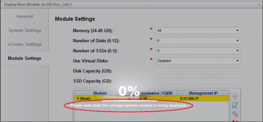
Figure 9-127 Module deployment started
12. When the module deployment process is complete, a window opens in which it is indicated that the module was not equipped, as shown in Figure 9-128. In the case of module repair activities, this behavior is normal and can be ignored.
|
Note: Equipping a module is necessary only if a new module is added to the system. Module replacement does not include adding modules.
|

Figure 9-128 Module was not equipped message
13. On the VMware ESXi server, the deployment process tasks are available for review in the Recent Tasks pane at the bottom of the window, as shown in Figure 9-129. The following main steps are shown:
a. Deployment of the OVF (Open Virtualization Format) template. This step requires the most time because it transfers about 400 MB of data to the module.
b. Establishing the VMware ESXi data store and RDM mapping files for the local HDDs.

Figure 9-129 VMware deployment tasks
14. After the deployment process is complete, the module must be tested and phased into the system to complete the module repair. By using the IBM XIV Management GUI, browse to the System view for the IBM Spectrum Accelerate system and right-click the module to show the menu. Select Test to being the component test of the replacement module, as shown in Figure 9-130.

Figure 9-130 Test the replaced module
15. The IBM XIV Management GUI now shows a view that indicates that the module entered the Initializing state. During initialization, the module undergoes various tests to verify that all required components are present and ready to be used. Within a matter of minutes, the module state changes from Failed to Initializing and the red triangles turn yellow, as shown in Figure 9-131.

Figure 9-131 Module:1 in initializing state
|
Note: Allow the module to complete the testing process and have a state of Ready. This process can take time because of the battery of tests that are being conducted on the module.
|
16. Right-click the module and select Phase in, as shown in Figure 9-132. This step is the last step of the manual recovery actions.

Figure 9-132 Module:1 phase in
|
Note: The phase in process is run in the background and completes after all the data on the system is redistributed to account for the new disk. The amount of time it takes to complete the phase in process can span many hours, depending on the amount of data, number of modules and disks, and the interconnect bandwidth of the system.
|
17. The phase in process continues until the system reaches the Full Redundancy state, as shown in Figure 9-133.

Figure 9-133 Module disks phasing in (redistributing)
Figure 9-134 shows a typical pattern of a test and phase in of a module. There is no view of the actions that were taken on the VMware ESXi server because the IBM Spectrum Accelerate system has no visibility to the underlying layers.

Figure 9-134 Phase in process steps
..................Content has been hidden....................
You can't read the all page of ebook, please click here login for view all page.