
Chapter 5: Core Revit Functionalities
Revit's core functionalities are the native Revit tools that do not use visual programming or additional plugins to manage model geometry and data.
We can gain productivity with Revit's core functionalities by planning ahead using the best workflows in a project and understanding their key functionalities. We need to think critically about how we will spend our time in Revit to become more efficient and analyze possible consequences, if we decide to use a specific workflow.
Before we start a specific task, we need to research quality information to ensure that we have enough details to successfully complete the task and think about why we have decided to use a specific process, as well as its benefits. We need to focus our time and energy on the workflow, which will significantly impact our tasks and deliver the required results.
Adopting the best Revit practices while you fully understand the problem you wish to solve will improve your effectiveness in BIM projects.
This chapter will provide you with knowledge about the best practices for schedule management and how to use Revit Keynote for specification. We will also look at Design Options, Revit Phasing, Scope Boxes, Worksharing, and drawing production best practices.
The following topics will be covered in this chapter:
- Understanding schedule management
- Keynote for the project specification
- Design Options, Revit Phasing, and Scope Boxes
- Worksharing and drawing production best practices
Understanding schedule management
You can use Revit schedules to create a list of components from your model that automatically update when the model changes.
In Revit, six schedule types are available:
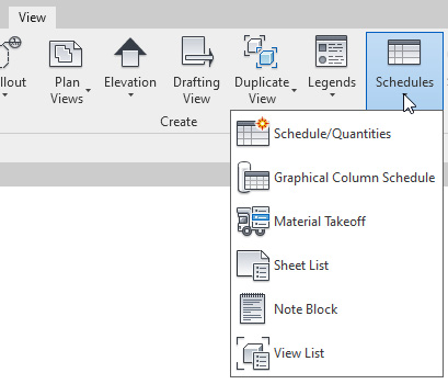
Figure 5.1 – Revit schedule types
Let's look at these in detail:
- Schedule/Quantities
This schedule type is the most used schedule to quantify elements in the model. You can find multiple object categories here, such as Curtain Panels, Doors, Furniture, Rooms, Walls, Windows, and others.
- Graphical Column Schedules
Graphical Column Schedules are used to visualize a column's height, size, and material in a chart.
- Material Takeoff
The Material Takeoff schedule type calculates the materials in the project. We can use it to estimate quantities and for support cost analysis.
- Sheet List
The Sheet List schedule type lists all the sheets in the project. It can provide an overview of all project sheets.
- Note Block
The Note Block schedule type helps make annotation text more efficient, and it gets updated across multiple views.
- View List
The View List schedule type lists all the views that are available in the project.
Now, we will present multiple processes that support Revit schedule management. We have divided the Revit schedule processes into Basic and Advanced to cover multiple levels of experience.
Basic Workflow
In the Basic Workflow, have the following processes, which help improve productivity.
Editing tools
We can find most of the editing tools in the Properties section. We can choose to edit Fields, Filter, Sorting/Grouping, Formatting, Appearance, and more:
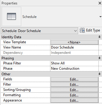
Figure 5.2 – Revit schedule editing tools
Freeze the Schedule Header
When we need to scroll a schedule up and down and keep the schedule header visible, we can use the Revit Freeze Header tool:

Figure 5.3 – Revit schedule – Freeze Header
Zoom IN and OUT of a Schedule
In the latest Revit versions, we can zoom IN and OUT of schedules.
If you open any Revit schedule, you can use Ctrl + "+" to zoom in and Ctrl + "-" to zoom out the schedule. However, the most practical process is to hold the Ctrl key and rotate the mouse wheel to zoom into the schedule.
Tip
To return to 100% zoom, just press Ctrl + 0.
Highlight Rows with Different Colors
In this workflow, we can highlight alternate rows with different colors. Follow the steps shown in the following image:

Figure 5.4 – Highlighting rows with different colors
Here, we can see rows with alternate colors that facilitate reading the schedule:

Figure 5.5 – Schedule rows with different colors
We can also turn on this feature by clicking on Stripe Rows:

Figure 5.6 – Schedule – Stripe Rows
Highlight in Model
This tool is useful for highlighting a particular door, room, or other Revit component in the model. We need to select a row and click Highlight in Model:
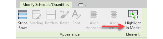
Figure 5.7 – Highlight in Model
Adding Images to Families and Display in Schedules
We can add images of objects to be associated with Revit families and display them on a schedule. Follow these steps to do this:
- Select a furniture chair family in the project and click Edit Family.
- Click on the box to select an image file (*.JPG). We must use the Type Image parameter:

Figure 5.8 – Type Image parameter
- Click …, select the image, and click OK. Load the family back into the project.
- Add the Type Image parameter to the schedule:
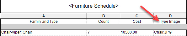
Figure 5.9 – Type Image parameter in the schedule
- Add Furniture Schedule to the sheet; you will see the product image:
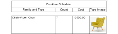
Figure 5.10 – Furniture Schedule with product image
We can also use the Image parameter to add images to be displayed in schedules:
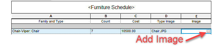
Figure 5.11 – Using the Image parameter
With this, we can control the image inside the Revit project instead of inside the Revit family.
Design Options in Schedules
In this workflow, we can display the quantities of objects from Revit Design Options in schedules. You must have Design Options in your project to use this workflow and select which options we want to display in the schedule.
Open the Revit schedule and follow these steps to change the specified Design Option:

Figure 5.12 – Design Options in Revit schedules
Schedules for Existing and New Phases
We can also create schedules for specific Revit phases, such as Existing or New Construction.
We can open the schedule and select the required Revit phase in Properties:

Figure 5.13 – Revit phases in schedules
Calculate Totals
We can calculate the totals in a schedule to find the total internal area of a building, specific floor, or total quantities.
To calculate totals, follow these steps:
- Let's edit a room schedule and select the Area parameter to calculate the totals in the Formatting tab:

Figure 5.14 – Calculate totals
- In the Sorting/Grouping tab, select Sort by: Level and tick the Footer and Grand Totals options:

Figure 5.15 – Calculate totals
After clicking OK, we will be able to see the total area that's been calculated.
Advanced Workflow
In the Advanced Workflow, we can resolve more difficult tasks in the project.
Conditional Formatting
Conditional Formatting is a process that's used to compare data and highlight a specific value based on its assigned rules.
Let's say we want to identify rooms with an area greater than 100 m2. Here, we can use the Conditional Formatting option to do this.
Follow these steps to work with Conditional Formatting:
- Open a room schedule that contains the Area parameter.
- In the Formatting tab, select the Area parameter and click Conditional Format…:
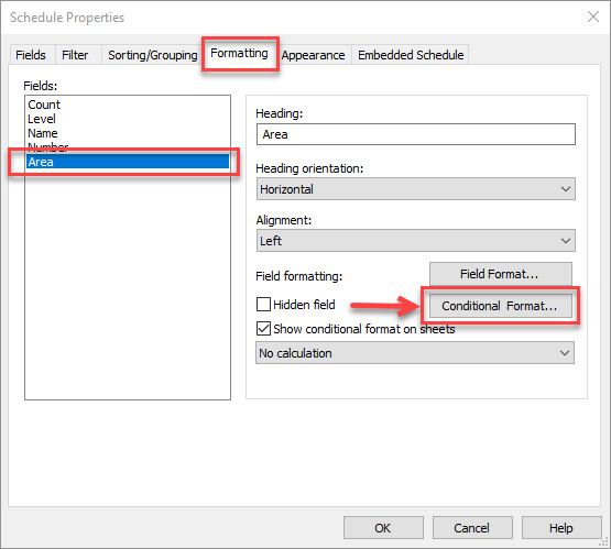
Figure 5.16 – Conditional Format…
- Select the Greater Than option, type in 100, select a Background Color, and click OK:
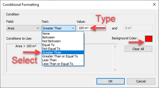
Figure 5.17 – Conditional Formatting options
We will see all the areas that are greater than 100 m2 highlighted in red:

Figure 5.18 – Areas highlighted with Conditional Formatting
Calculated Fields
We can create new parameters in the schedules with formulas and calculate the percentage.
Follow these steps to calculate the total area percentage:
- Create a room schedule with the following fields: Count, Level, Name, Number, and Area.
- Click on Edit… next to Fields and click on fx, labeled Add Calculated Parameter in the following diagram:
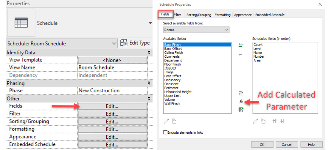
Figure 5.19 – Add Calculated Parameter
- Type in Area Percentage as the parameter's name, select Percentage, and click OK:
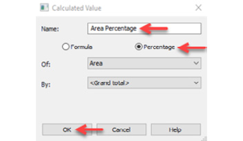
Figure 5.20 – Calculated Area Percentage
- Now, let's format the Area Percentage units so that they include two decimal places. In the Formatting tab, select Field Format, change Rounding to 2 decimal places, and click OK:

Figure 5.21 – Field Format with 2 decimal places
We will see Area Percentage calculated in the schedule:
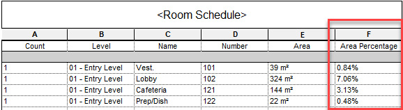
Figure 5.22 – Area Percentage calculated with two decimal places
We can also use Calculated Fields to add formulas and calculate multiple values, such as the following:
- Cost per area or calculate the general cost.
- Compare your designed areas with the client's requirements for areas.
- Use formulas to add construction tolerances.
- Calculate the weight per square meter and other functionalities.
To conclude, we have learned about schedule management's key aspects that can support the creation of efficient schedules in Revit. In the next section, we will learn about Revit Keynote, which is used for the project specification. This speeds up the process of adding text annotations.
Keynote for the project specification
Keynote is an essential feature for assigning a project specification to element types, individual families, and materials. These processes will save you a lot of time adding notes to your Revit project.
Before you can use Keynote, the project team needs to decide which construction specification standards will be implemented.
In the UK, the construction industry has used the Common Arrangement of Work Sections (CAWS) codes for many years, but it is no longer maintained. Projects are increasing their usage of Uniclass 2015 codes for the specification.
In North America, the construction industry may use OmniClass, which is equivalent to Uniclass, or MasterSpec as the specification system.
Companies may use other specification systems as a project requirement.
We can find the Keynote tool in the Annotate tab:

Figure 5.23 – Revit Keynote
Before you can annotate objects with Keynotes, you need to receive the Keynote text file (*.txt) from your project specification team or use Autodesk's text file and edit it as necessary.
Click on Keynoting Settings to find the text file's (*.txt) location:

Figure 5.24 – Revit Keynote text file (*.txt)
The file path's location is C:ProgramDataAutodeskRVT2021LibrariesUKRevitKeynotes_GBR.txt.
In Keynoting Settings, we can also click Browse to locate the text file.
The Keynote text file needs to be copied to your project folder and renamed as required. Usually, the filename will have project code + project name + keynotes in the filename's description.
We can visualize the specification code by clicking View:

Figure 5.25 – Visualizing the Keynote text file (*.txt)
When the Keynote file is updated during the project, we need to click on Reload to reload the Keynote file.
Keynote types
There are three ways we can add keynotes:
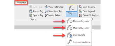
Figure 5.26 – Keynote options
Let's look at these in detail:
- Element Keynote
We can apply the Element Keynote to component and system families, including walls, floors, roofs, and other Revit families.
The Element Keynote will use the Keynote type parameter to add the specification code as keynote text:

Figure 5.27 –Keynote type parameter
We can select the keynote specification code from the list of Keynotes:
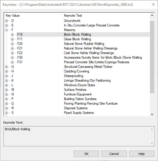
Figure 5.28 – Keynote type parameter
- Material Keynote
In the Material Keynote, we can add the specification for the material instead of the whole family, as in the previous method:

Figure 5.29 – Material Keynote
This method is useful when we want to add the specification to individual materials such as bricks, plasterboards, glazing, and others.
- User Keynote
The User Keynote method is not frequently used as the keynote specification is not associated with Revit components.
We can still use the keynote specification list to add annotations to drawings, but it will lose its intelligence and connections with Revit components.
Annotating drawings with Keynote
The Revit Keynote process will improve our efficiency of annotating drawings because the specification will be associated with objects. If we change the keynote text, it will automatically update in all views and drawings. Keynote's intelligence is essential to increasing productivity when producing and annotating drawings.
The process of adding Keynote is simple – we can adopt one of the three aforementioned methods and select a Revit component. Follow these steps to add a keynote:
- Let's click Element Keynote and select a wall in a plan view.
- We will see a question mark symbol. Upon clicking a second time to place the annotation, we will be able to select the specification's keynote text:
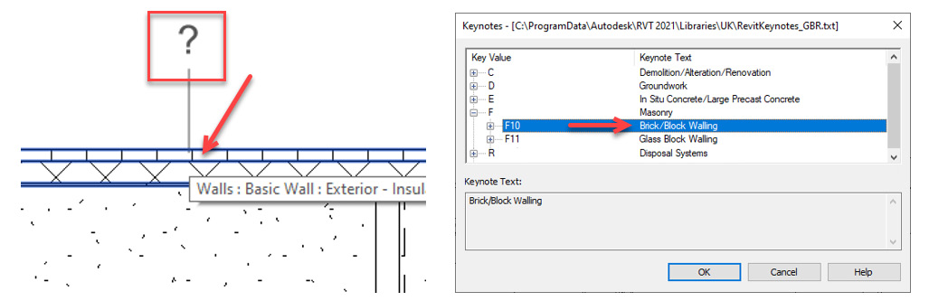
Figure 5.30 – Selecting the keynote text
- After clicking OK, we will see the Keynote assigned to the wall:
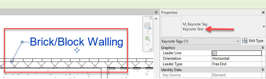
Figure 5.31 – Keynote assigned to the wall
To conclude, we have learned how to improve productivity and efficiency to annotate drawings with Keynote. In the next section, we will learn about the best practices of Revit's Design Options.
Design Options
Revit's Design Options let you have more than one design solution in the same Revit file. We can switch between Design Options, which helps us design meetings and with client's presentations.
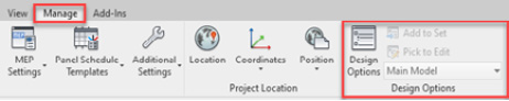
The process of creating Design Options is relatively simple, and we will focus on the best practices for managing Design Options to improve our productivity and efficiency. We can find the Design Options tool in the Manage tab | Design Options:
Tip
When using Design Options, it is better to have "hosting" and "element hosted" in the same Design Option; for example, a wall (hosting) and a door (hosted).
Let's learn about the best practices for managing Design Options in Revit.
Naming Design Options
Revit Design Options should be named based on your company standards and avoid using the default naming conventions such as "Option 1," "Option 2," and so on.
When we provide our Design Options with meaningful descriptions, we improve team communication and help team members save time identifying which Design Options needs to be selected or updated. We can rename an Option Set, as well as individual options:
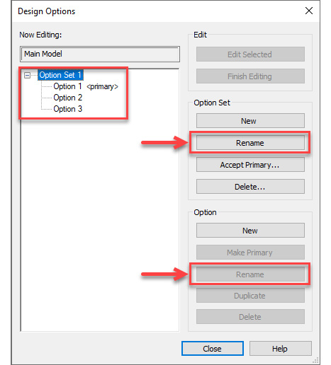
Figure 5.33 – Rename – Design Options
Design Options Visibility
When we want to display a specific Design Option in a Revit view, we can overwrite the Primary Option and display another Design Option. This process helps us print or show multiple designs.
By working with the Enscape Revit plugin, we can show the rendering of multiple design options in real time very quickly.
To select which Design Options we want to change the visibility of on a view, follow these steps:
- Open the view that you want to change the Design Option for.
- Under Properties, click on Visibility/Graphics Overrides (we can use the VV or VG shortcuts to do this:

Figure 5.34 – Overwrite the Primary Design Option
- Under the Design Options tab, select the required Design Option:

Figure 5.35 – Overwriting the primary Design Option
This process will allow us to change Primary Option to another Design Option, such as Extended Kitchen Area or Open Space, as shown in the preceding screenshot.
It's worth mentioning that the <Automatic> option will display the Primary Option.
Now, let's learn how to do the same process when we're working with Linked Files. If you have multiple Linked Files and you want to change the Design Option, follow these steps:
- Under Properties, click on Visibility/Graphics Overrides (or type VV or VG as a shortcut).
- We will see a new tab called Revit Links. Click on Revit Links and then By Host View:

Figure 5.36 – Selecting By Host View
- In the Basics tab, select Custom:

Figure 5.37 – Selecting Custom to enable this process
- In the Design Options tab, select <Custom> from the drop - down menu and select <Automatic> to change the required Design Option from a Linked file:
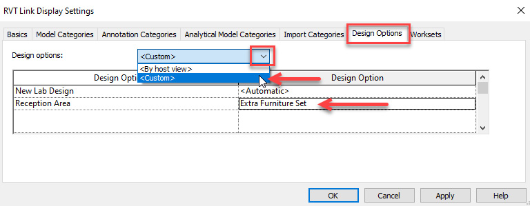
Figure 5.38 – Changing a Design Option from a Linked file
Schedule Design Options
We can create a Revit Schedule to show the quantities that are provided in Design Options. If we don't change these settings, Revit will always display the quantities in the Primary Option.
To create a schedule and display a different Design Option, open the Revit Schedule and follow the steps highlighted in the following image:

Figure 5.39 – Changing the Design Options for Revit schedules
Empty Design Options
We may need to create an empty Design Option when we don't need to show new geometry in the Primary Option. In this situation, the Primary Option will be empty, but the other Designs Options will have geometry.
Increasing Performance With Design Options
Multiple Design Options in a Revit file can reduce performance, and it is essential to remove unused Design Options and views frequently.
We need to consider what is included in a Design Option wisely so that we have good Revit performance. If the Design Option is a large portion of a building, we may consider creating a new Revit file to link instead of creating a Design Option.
Before removing Design Options, we advise that you back up the Revit file with all the Design Options in case the project team needs to return a specific design option in the future.
After removing the unused Design Options, we recommend running the Purge command to remove unused families. This reduces the file size and improves performance.
Issuing Revit Models Without Design Options
When you're issuing Revit files to consultants, all the Design Options need to be removed to keep the Revit files optimized for good performance.
If required, we can keep specific Design Options based on whether the project team agrees.
In this section, we have learned about the best practices surrounding Design Options to gain productivity. In the next section, we will learn about Revit Phasing.
Revit Phasing
Revit phases are an excellent function for working with existing buildings as they allow us to distinguish elements from different Phases and Phase Statuses, such as Existing, New, Demolished, and so on. It also helps us control their visibility.
In Chapter 3, Revit Templates and Standards, we showed you how to implement Revit Phases for Revit templates. In this section, we will present the best practices for using Revit Phases.
Depending on your project's size, we advise having one Revit file for the Existing Phase and another Revit file for the New Phase. Although we may use just one Revit file with both Phases for a single house project, we can gain productivity by using separated files for each Phase in medium and large projects.
Revit File with Only the Existing Phase
This Revit file will only contain the surveyed model for the existing building, and it will only be used to demolish objects.
We can use the Demolish tool from the Modify tab and select objects as required:
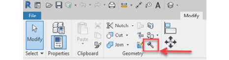
Figure 5.40 – The Demolish tool
Revit File with Only the New Phase
This Revit file will contain only the New Phase with new objects. The design team links the Revit file containing the Existing phase to this file, which only contains the new design.
This workflow proposes a clear separation between the Existing and New phases, which can help design teams gain productivity. It helps save you time managing objects from different Phases. It will also increase productivity when we need to create schedules or provide Asset Management data that only comes from the Revit file that contains the New phase.
Once we've done this, we can link the Revit file containing the Existing phase to the Revit file containing the New phase and use it as a background to develop the design:

Figure 5.41 – Linking the Revit file containing the Existing phase to the New phase
We can add multiple Phases to a project, but it is common to only see the Existing and the New phases being used in various projects.
Phase Filters
The Phase Filters that were originally created in Revit are not intuitive and are barriers to understanding and usability, so we advise deleting rows 2 to 7:
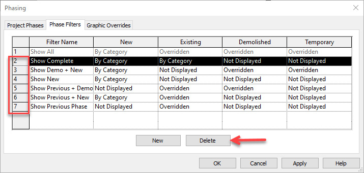
Figure 5.42 – Revit Phase Filters to be deleted
We can increase productivity by recreating new Phase Filters as required in our project, thus facilitating usability. The Phase Filter description is essential to keeping things simple.
We suggest the following naming convention:
Sequential number + description + graphic overrides description
Some examples are as follows:
- 01-Existing-By Category
- 02-New-By Category
- 03-Demolition-By Category
- 04-Existing and New-By Category
- 05-Existing and New-Overridden
- 06-Existing and Demo-Overridden
- 07-New and Demo-Overridden
In Phase Filters, we can create multiple combinations and control Phase Filter overrides:

Figure 5.43 – Revit Phase Filters with new naming conventions
In Phase Filters, there are three options we can choose from: By Category, Overridden, and Not Displayed.
When we select a specific Phase Filter, it will display its Graphic Overrides:
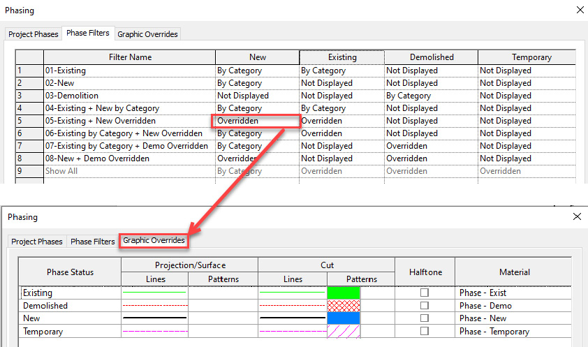
Figure 5.44 – Phase Filters and Graphic Overrides tabs
We can change Phase Filter and Phase in the Properties section as required by View. This is a quick way to update any view that is not displaying correct information:

Figure 5.45 – Changing the Phase Filters and Phase by View properties
Phase – Graphic Overrides
Graphic Overrides can be updated based on your company standards, and we can choose different colors to represent each Phase Status. The following Phase Statuses are available:
- Existing
- Demolished
- New
- Temporary
The following screenshot shows the options for changing the Graphic Overrides options:

Figure 5.46 – Revit Phases – Graphic Overrides settings
Tip
"Demolished" is the Phase Status of an object and not a Revit Project Phase.
When working with Phases and Graphic Overrides, we may notice components that are not in the correct Phase. To resolve these issues, we can select the components and change their Phase in the Properties section:

Figure 5.47 – Changing a Revit Phase
Displaying multiple phases from Linked files
Let's learn how to display multiple phases from Linked files in the same view. If we have multiple Linked files and we want to display various phases, then we must follow these steps:
- Under Properties, click on Visibility/Graphics Overrides (we can use the VV or VG shortcut here):

Figure 5.48 – Changing a Revit Phase
- We will see a new tab called Revit Links. Click Revit Links and then By Host View:

Figure 5.49 – Changing a Revit Phase By Host View
- In the Basic tab, select Custom and select the required Phase or Phase filter from the drop - down menu:
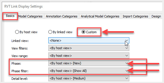
Figure 5.50 – Changing the linked Revit Phase or Phase Filter
In this section, we learned about how to manage Revit Phases to gain productivity. In the next section, we will learn about Scope Boxes, which help control the crop region of multiple views.
Using Scope Boxes
Scope Boxes can increase efficiency by applying a specific crop region to multiple views and control Levels and Grids extensions.
Scope Boxes are created in the Floor or Ceiling Plan views, but they are visible in multiple views and can be adjusted as required.
To create a Scope Box, select the Scope Box tool from the View tab:
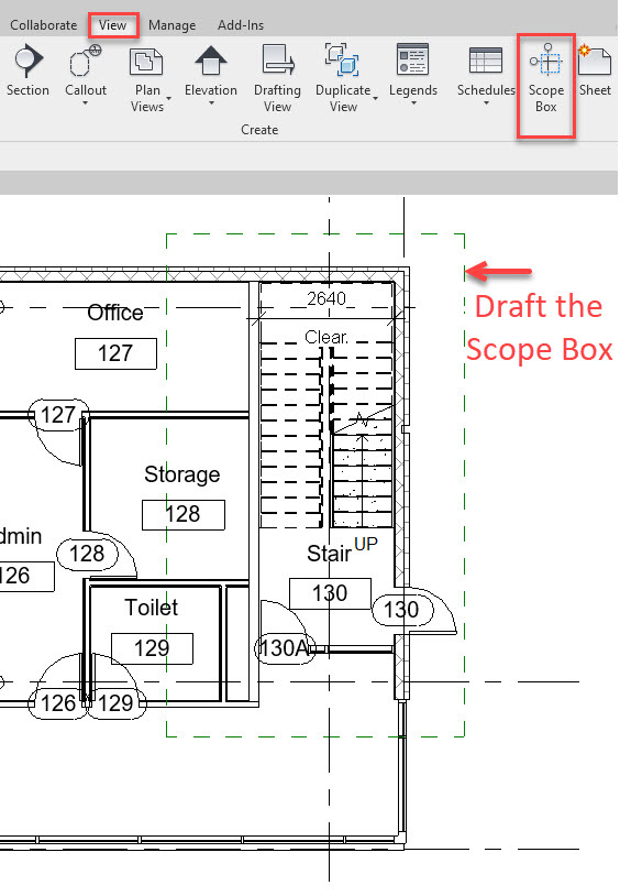
Figure 5.51 – Drafting the Scope Box in a plan view
After adding the Scope Box, we need to select and name it. Usually, the name should be a description of the area that you are cropping:
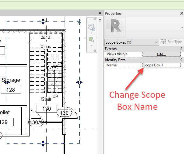
Figure 5.52 – Changing the Scope Box's name
Once the Scope Box has been created, we can select it from Properties to crop its view:
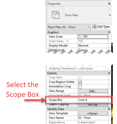
Figure 5.53 – Selecting and applying the Scope Box to a view
Now, we can select multiple views from the Project Browser menu and apply the same Scope Boxes:

Figure 5.54 – Selecting and applying the Scope Box to multiple views
If we need to edit the Scope Box area, we need to select the None option to make the view crop region editable:
Tip
Tick the Annotation Crop option to hide annotations outside the Scope Box.

Figure 5.55 – Ticking the Annotation Crop option to hide annotations outside the Scope Box
Rotating a Scope Box
Rotating a Scope Box can increase our productivity if we are working in a building wing that is not horizontal or vertical. After rotating the Scope Box, we can draft in Revit using horizontal and vertical axes, which is easier than drawing an angle. Follow these steps:
- To start, we need to create a Scope Box and rotate it as required:

Figure 5.56 – Creating a Scope Box and rotating it as required
- Apply the Scope Box to a view. You will need to zoom out and find the rotated view:

Figure 5.57 – Horizontal view with a rotated Scope Box
As we can see, the view is rotated horizontally and can carry on working in this view as required. Now, if we want to rotate the view in a different direction by using Scope Boxes, we need to follow these steps:
- Select the Scope Box. We will see the Scope Box rotation symbol, which is at the top right:

Figure 5.58 – Scope Box rotation symbol
- Use the Rotate tool to rotate the Scope Box as required. In the following image, we can see that the Scope Box rotation symbol is at the bottom left before we assign the Scope Box to a view. Once we've assigned the Scope Box to a view, the view will be rotated so that the rotation symbol is at the top right:

Figure 5.59 – Before and after rotating the Scope Box
In this workflow, we can see that after assigning the Scope Box to a view, the view will rotate to place the rotation symbol at the top right.
In this section, we learned how to use a Scope Box to increase productivity. In the next section, we will learn about Worksharing in Revit.
Worksharing
Worksharing in Revit is a process that allows multiple users to work simultaneously in the same Revit file.
We can collaborate with multiple users by adopting the Central and Local files workflow.

Figure 5.60 – Synchronizing with Central and Local files
How to create a Revit Central file
Let's learn how to create a Revit Central file. Follow these steps:
- Save the initial Revit file in the correct folder and with the appropriate naming convention. In Chapter 4, Starting a Revit Project Efficiently, we learned how to start a Revit project and set up the project's coordinates, so this will be the initial file that contains the correct coordinate system.
- In the Collaborate tab, click on Collaborate:

Figure 5.61 – Collaborate tool
- Let's assume that we are working in your private network and not using the Autodesk BIM 360 cloud platform. Select the Within your network option and click OK:
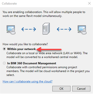
Figure 5.62 – Collaborating within your network
- Click Save in the Quick Access bar:

Figure 5.63 – Save
- A new window will appear. Click Yes:
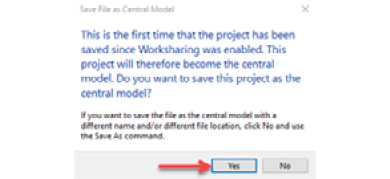
Figure 5.64 – Enable Worksharing
- Click on the following option to synchronize:

Figure 5.65 – Synchronize with Central
- Tick the User-Created Worksets option and click OK:
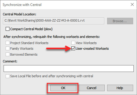
Figure 5.66 – Synchronize with Central
Now we've created a Revit Central file, we should close it.
Tip
We should never work in the Central file as it will cause problems with Worksharing, and the Local files will stop working.
We can now invite other users to collaborate in the same file by creating their Revit Local files. it's useful to create the project Worksets as required.
We will learn about Revit Worksets later in this section.
How to create a Revit Local file
Let's learn how to create a Revit Local file, which is the working file that users will be continually creating to collaborate and work on the project.
Each team member will have their own Local file to work in, and we will make a new Local file every time we want to open a Revit file that is using Worksharing. You need to have a Revit Central file to create a Revit Local file. The Local file should be saved on your computer and not on the company drivers' network.
To create a Revit Local file, follow these steps:
- Start Revit.
- Click Open and browse to locate the project's Central file. Then, select it. The Create New Local option will be automatically selected. Click Open:
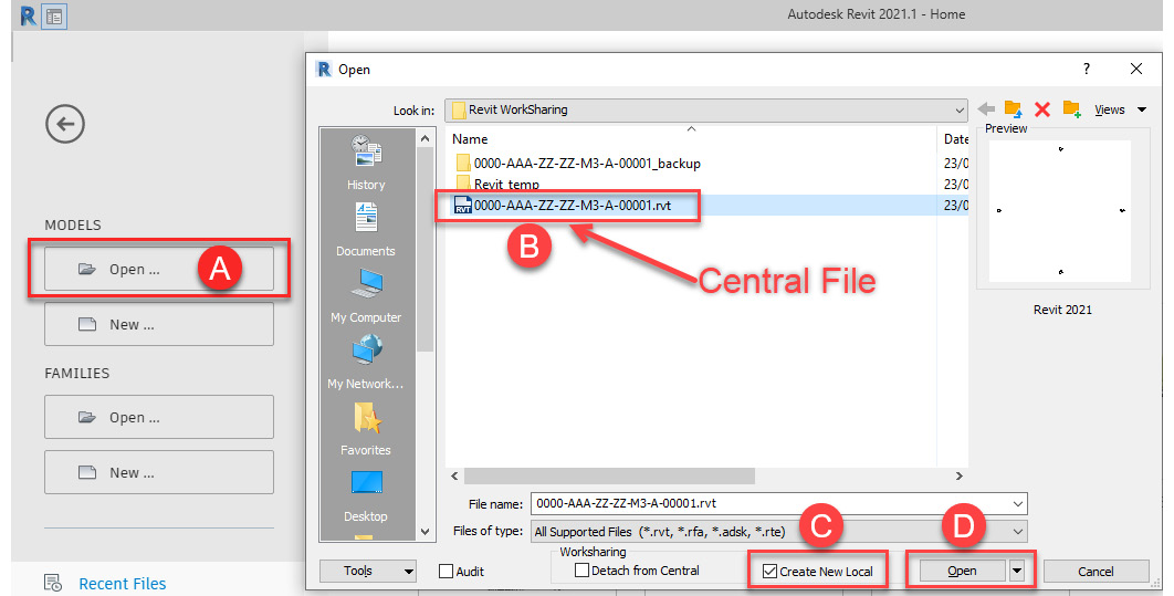
Figure 5.67 – Creating a Revit Local file
Now that the Revit Local file has been created, we can see our username or Autodesk ID in the filename:

Figure 5.68 – Revit username
We should repeat this process to create a new Local file every time we want to work on a project with Worksharing enabled and Central files.
After creating the Local file, we can work in the Revit file, but we need to Synchronize to save our work back to the Central file as necessary. There are two options for synchronizing, as shown in the following image:
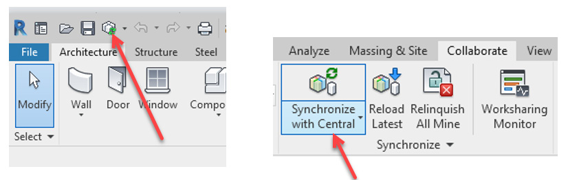
Figure 5.69 – Synchronizing to the Central file
We should Synchronize every 30 minutes or every time we make a significant change to the model. This will "relinquish" the objects that you have control over back to the Central file so that other users can have access to those objects.
Best practices for Worksharing
The following best practices for Worksharing will help you avoid issues and maintain good Revit performance.
Worksets
Worksets is a tool that allows us to create a collection of objects that we can unload (Close) and reload (Open) and control the visibility of in a view.
There are two main benefits of Worksets:
- Improve Revit performance: When objects are unloaded (Closed), Revit will perform faster.
- Improve your performance: Control the object's visibility to hide unnecessary geometry to improve your performance when working on a specific task.
A list of typical worksets can be found in the following file, which you can find in the dataset for Chapter 3, Revit_Template_Check_List.xlsx:

Figure 5.70 – Worksets List
The process of creating worksets is simple. Follow the steps shown in the following screenshot:
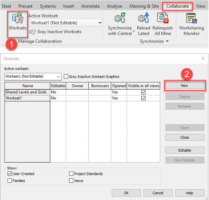
Figure 5.71 – Creating Worksets
The following are the best practices for managing worksets:
- Create one Workset for every linked model. This will help unload unnecessary links. There is also another option for unload links called For me under Manage Links:

Figure 5.72 – Option to unload links
- Create one Workset for all CAD/DWG files. Note that these files will be linked instead of imported.
- Avoid creating a large number of worksets. Less than 20 Worksets should be able to support most project types.
- Close the worksets that you don't need so that Revit performance improves.
- When you're creating a Local file, selecting which Worksets we want to close by choosing the Specify… option will make Revit open the file quicker:
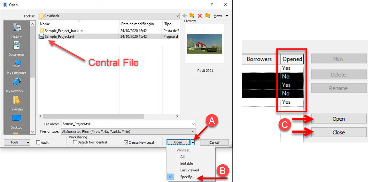
Figure 5.73 – Closing Worksets when creating a Local file
We can make the Specify… option the default option by recreating the Central file with the Save As option:

Figure 5.74 – Setting the Specify option as the default
- Revit components must be added to the correct workset, which will increase productivity and help control visibility and performance.
- Keep a good naming convention for Worksets.
- Levels and Grids should be on the Shared Levels and Grids workset.
- You can control the Workset's visibility by using a specific view:

Figure 5.75 – Controlling the Workset's visibility in a specific view
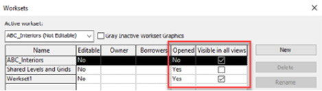
Figure 5.76 – Controlling the Workset's visibility across the project in multiple views
- Synchronize with the Central file frequently to relinquish objects from Worksets.
- Avoid deleting or renaming the default worksets:
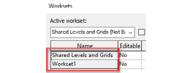
Figure 5.77 – Default Workset
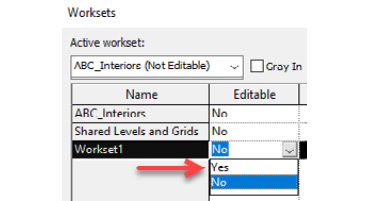
Figure 5.78 – Avoid making the Workset editable
- The Worksharing Display Settings option enables us to color code Worksets:

Figure 5.79 – Color-coding Worksets
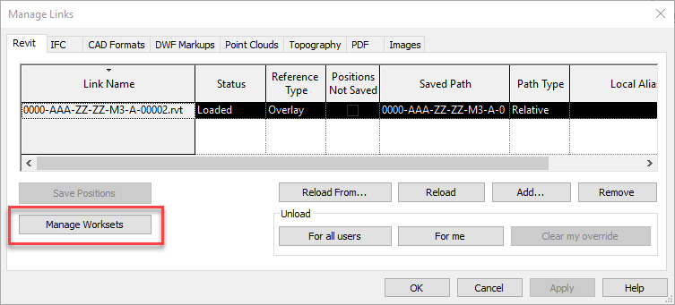
Figure 5.80 – Managing Worksets from linked files
Tip
The quickest way to access Manage Worksets is by going to the Project Browser, right-clicking, and selecting Manage Worksets:
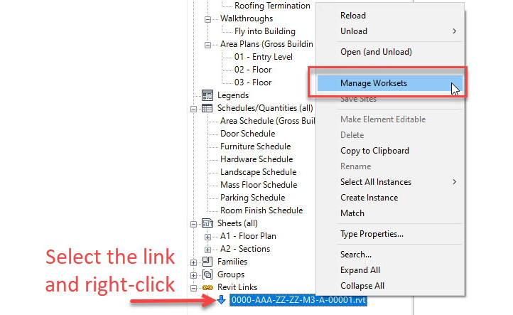
Figure 5.81 – Selecting Manage Worksets
Local File Saving Path
The Local file should be saved on your local computer on its local hard drive, not on your company's network drives:
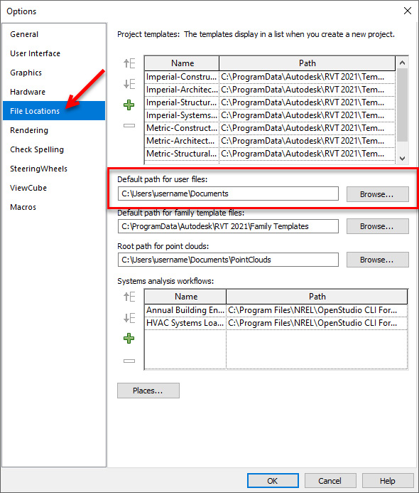
Figure 5.82 – Path for Revit Local files
We recommend creating a dedicated folder to save the Local files in, such as Revit_20XX_Local_Files (where 20XX is the Revit version), so that the Revit files aren't mixed up with other files located in the Documents folder.
The default path for the user files is C:Users<username>Documents Revit_20XX_Local_Files.
Username
The Revit Username is used to identify your Local file. The Autodesk license that utilizes Single Sign-On (SSO) automatically defines this Username based on your Autodesk profile:

Figure 5.83 – Username
Worksharing Monitor
Worksharing Monitor is used to identify users in the model and choose the best time to synchronize them. This helps save time if we're wait for other users to complete this process:
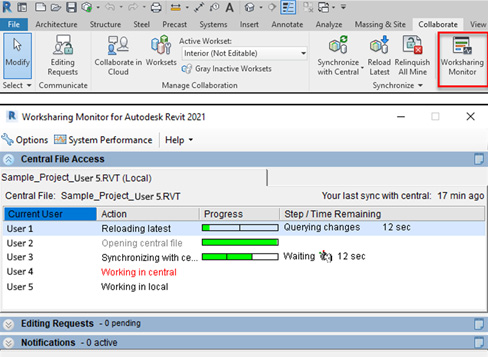
Figure 5.84 – Identifying users in the model with Worksharing Monitor
Central File Maintenance
The Central file needs to be audited and compacted from time to time to improve its performance and reduce any risk of file corruption. The following points are essential for managing Central Files:
- Audit Central files from time to time:

Figure 5.85 – Auditing a Central file
- When you're synchronizing the Local file, Compact the Central file from time to time:

Figure 5.86 – Compact Central Model (slow)
- If necessary, use the Restore Backup option to roll back changes that were made to the Central file:

Figure 5.87 – Restore Backup
- We can find our synchronization history under the Show History option, which helps us identify the last person to synchronize the model and its comments:
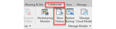
Figure 5.88 – Show History
- Recreating the Central file requires all users to be out of the project. This can also be applied to other maintenance tasks.
- To open the Central Model for maintenance, untick the Create New Local option:

Figure 5.89 – Opening the Central file
- There are two options for issuing Revit models: click Open and select Detach from Central or select the Transmit model(s) tool from the Add-ins tab:

Figure 5.90 – Issuing Central files
Local files
The following points are essential for managing Local files:
- We should create a new Local file every time we want to open the Revit file.
- Always work from the Local file.
- Never open an old Local file or use the icons on Revit's opening screen:
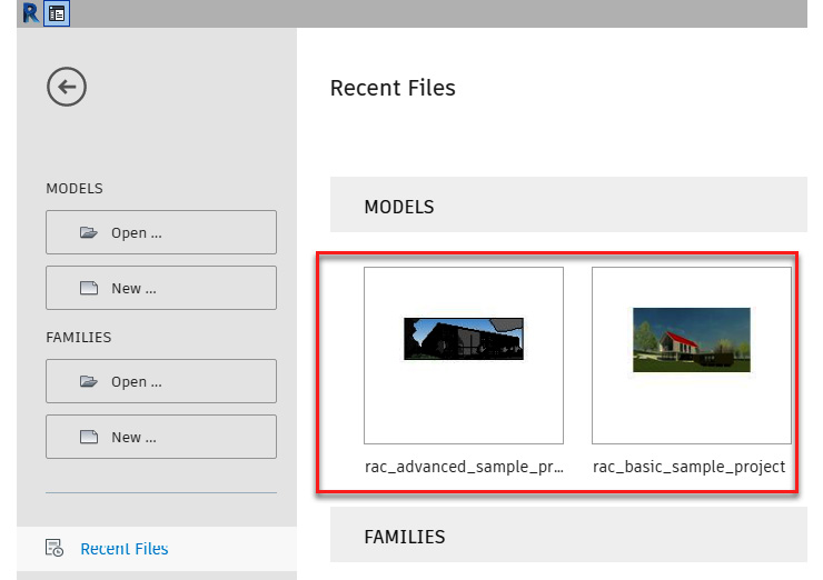
Figure 5.91 – Recent Files – Revit opening screen
- Synchronize frequently. We recommend doing so every 30 minutes or every time you make a significant change to the model.
- Avoid keeping the Local file open and inactive for a long period of time. It may slow down the Local files of your team, and it will take longer to synchronize. If you're going to a meeting, lunch, or leaving the company in the evening, close your Local file.
- Synchronize the Local file before closing it. We can also save time if we choose Relinquish All Mine first before choosing to Synchronize:

Figure 5.92 – Relinquish All Mine
- If we want to close the file without saving, select the Relinquish all elements and worksets option:
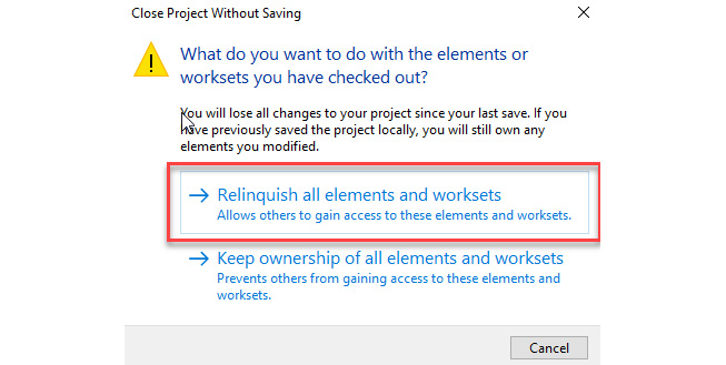
Figure 5.93 – Relinquish all elements and worksets
- Follow the Revit Recommended Settings options from Chapter 1, Introduction to Productivity in Revit, to model economically and keep the file sizes small.
- Replacing the Consultants model with a new version that must keep the Revit file with the same name to avoid losing your overwriting settings. When you receive a new file, the filename needs to be identical and not have an issue date. The filename must not have been revised.
You may be wondering, how can we identify which model revision is linked to our model?
We create folders for each revision (P01, P02, and so on), and when we link the Revit files from these folders, we can check the revisions in the file path by going to Manage Links:

Figure 5.94 – Identifying the Consultants model
Upgrading Central Files
Before we can upgrade Revit files to a new Revit version, we need to consider a few factors:
- If the project is at a late stage or in the Construction stage, consider working in the same version and not upgrading. That being said, if the required version is not available in the Autodesk Portal to be downloaded, you may need to ask for dispensation from Autodesk to use an old version of Revit.
- Before the upgrade, you must get the agreement of the whole team.
- Ensure that the Revit plugins you can used in the project can work in the new Revit version.
- Upgrade a Revit Detached copy to run the tests. If the tests run without problems, we can upgrade the main Central file. Select the Detach from Central and Audit options:
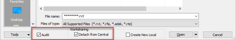
Figure 5.95 – Select the Detach from Central and Audit options before the upgrade
- Confirm that all the Revit versions involved in the upgrade have the latest Revit release updates.
- Start upgrading the linked files and then the main file, which contains all the links. If you upgrade the main file first, it will take longer to complete the process as each link needs to be upgraded in the background. We can also remove the links before upgrading.
- After upgrading, check the Revit file for lost geometry and data.
- If we are upgrading legacy files from many years ago, you may wish to upgrade to the latest version directly. If you find any problems, you can upgrade the file to an old version and move it to a more recent Revit version, every 2 or 3 versions, until you get to the required version.
In this section, we learned how to create Central file and Local files, as well as the best practices about Worksharing in Revit.
In the next section, we will learn about drawing production.
Drawing production
Efficient drawing production is an essential skill if you wish to master Revit and deliver a set of PDF and DWG files as project deliverables.
We can increase productivity for drawing production by focusing on three best practices:
- Plan the drawing list.
- Work with a good Revit template.
- Control drawing visibility.
Plan the Drawing List
At the beginning of each stage, we must plan the drawing list to be produced and avoid creating drawings as the project continues to be developed.
When we have a list of drawings, the project team or the BIM coordinator can quickly create all the sheets with the correct names, numbers, statuses, and other information. This process is essential for gaining productivity in delivering drawings. We can automate this process to create multiple sheets directly in Revit, or we can use the Dynamo and Revit plugins to speed up this process.
The key point is to make it clear what deliverables will be produced to the design team and assign team members responsibilities regarding drawing production.
Once the drawings sheets have been created, the project team or the BIM coordinator can populate most of the sheets with Revit views, even if the views haven't been completed or are very basic. As the project develops, the drawing sheets will start to take form, and the project manager can print the set of drawings to verify your progress.
This initial drawing set is called Cartoon Set, which helps you plan project deliverables. The Cartoon Set increases efficiency as we can ensure that the drawing set includes all the necessary information to be delivered.
As the projects are developed, the Cartoon Set will become a complete set of drawings, which helps ensure that we meet our deadlines smoothly and efficiently.
Tip
Creating multiple drawing sheets at the last minute before the deadline is a bad idea!
Work with a Good Revit Template
The drawing's production efficiency will depend on the Revit template's quality, which will include line weight, view templates, title sheets, and other Revit settings.
In Chapter 3, Revit Templates and Standards, we learned how to create and improve the Revit template.
The industry and organization standards included in the template will promote consistency across the project(s) and align them with the graphical and technical standards.
Control Drawing Visibility
We can control the drawing visibility in multiple ways, such as by using View Templates and other techniques, but a few processes can help improve productivity so that we can create drawings in PDF and DWG format.
The following can help you improve performance:
- Control the View Range settings to limit what Revit needs to calculate as geometry beyond what's necessary. The Primary Range Bottom and View Depth can be used to limit the calculated geometry, which will improve performance:
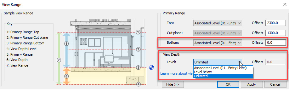
Figure 5.96 – View Range settings
- Control Far Clip Offset to display the required area only. Revit will increase performance when we limit the calculated geometry:
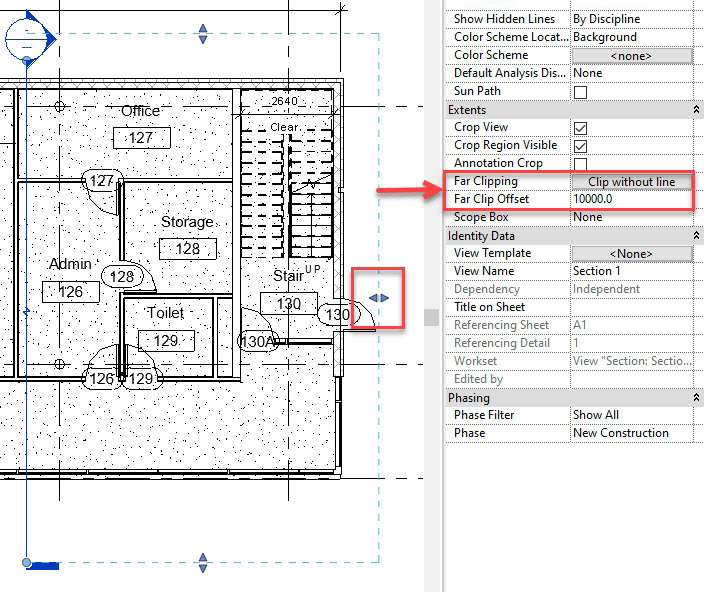
Figure 5.97 – Far Clip Offset
- Shadows will increase the time to create PDF files. Turn off shadows if they are not required.
- Check if the linked files are necessary for a specific view. Revit's performance will increase if we unload the unnecessary links.
- Ensure we have installed the latest printer driver or plugin installed to print PDF files. In Chapter 9, Enhancing Productivity with Plugins, we will learn more about Revit plugins.
In this section, we learned about three factors that can affect productivity when we're producing drawings in Revit.
Summary
In this chapter, we learned about the Revit core functionalities and best practices to improve efficiency when working with schedules and keynotes for construction specifications. The schedule workflows were divided into Basic and Advanced to help cover the essential processes for managing schedules.
In Revit, keynotes are used to assign construction specifications to Revit components, thus increasing productivity and consistency when we're annotating drawings.
We then explained the best practices and workflows for Design Options, Phasing, and Scope Boxes, which help us to be more efficient in our daily activities when we're working with Revit. We also learned about workflows for Worksharing so that we can collaborate with multiple users working simultaneously in the same file.
After that, we presented the three main factors for increasing productivity during drawing production, including defining the drawing list, working with a good Revit template, and controlling the drawing's visibility.
In the next chapter, we will cover visual programming with Dynamo and learn how to automate specific tasks in Revit.