
Active Intelligent Control
Abstract
In this chapter, principles and classifications of active intelligent control systems are introduced firstly, and basic contents of the active mass control system and active tendon control system, including the basic principles, the mathematical model, structural analysis, and engineering examples are presented. Finally, other active intelligent control systems are introduced briefly.
Keywords
Active intelligent control; active mass control; active tendon control
Active intelligent control was started in the 1950s, but the systemic research and practical application in civil engineering structures was started around 1990. The most common active control devices are active mass damper (AMD) system and active tendon control system. AMD system and active tendon control system will be introduced in detail based on the generally accepted principles and classifications.
3.1 Principles and Classification
3.1.1 Buildup of Systems
As described in Chapter 1, Introduction, active intelligent control system consists of sensor system, control system, actuator system, and other components. Sensor system measures the external disturbances or structural response information, and transmits them to the control system. The control system calculates the required active control forces based on a given control algorithm, and outputs control signals to the power drive system (converted by the control force through the control loop), then provides desired control forces on the structure to reduce the responses of the structure with the help of an external energy source. Buildup of systems includes buildup of the main frame and each system, and the main frame is generally built as shown in Fig. 1.9.
In the buildup of active intelligent control system, optimal control forces applied to structures are required to be determined in accordance with different working modes. There are two kinds of working modes, i.e., feedforward control (installing sensors on the foundation) and feedback control (installing sensors on the inner structure). The feedforward control mode is relatively simple, and the control forces can be adjusted real time in accordance with the excitation information, while the responses of structures are not reflected in the control process. Open-loop control system is the common control form for the feedforward control mode, and the schematic diagram is shown in Fig. 3.1(A). The feedback control mode is adjusting the control forces real time in accordance with responses of structures. Closed-loop control system is the common control form of the feedback control mode, and the schematic diagram is shown in Fig. 3.1(B). In addition, the two working modes can also work simultaneously by adjusting the control force, according to outside interference and comprehensive information, in order to achieve the goal of reducing structural dynamic responses.

3.1.2 Basic Principles
As described in Section 2.1, the equation of motion of the active intelligent control system can be written as Eq. (2.1), and the state-space equation can be expressed as Eq. (2.5), the control force ![]() can be expressed as
can be expressed as
(3.1)
where ![]() and
and ![]() are the feedback gain matrix of system state and a feedforward gain matrix of outside interference, respectively. Substituting Eq. (3.1) into Eq. (2.5), it can be obtained as
are the feedback gain matrix of system state and a feedforward gain matrix of outside interference, respectively. Substituting Eq. (3.1) into Eq. (2.5), it can be obtained as
(3.2)
Comparing Eq. (2.5) and Eq. (3.2), it can be seen that the values of structural dynamic property and exciting force change from ![]() and
and ![]() to
to ![]() and
and ![]() because of the action of control force. From the above result, it can be seen that the ideal controlled state of structure will be realized if the increment can be continuously and actively changed to keep it in the optimal state at all time. The modern cybernetics methods described in Chapter 2, Intelligent Control Strategies, can be adopted to realize the goal of ideal active control.
because of the action of control force. From the above result, it can be seen that the ideal controlled state of structure will be realized if the increment can be continuously and actively changed to keep it in the optimal state at all time. The modern cybernetics methods described in Chapter 2, Intelligent Control Strategies, can be adopted to realize the goal of ideal active control.
3.1.3 Classification
The active control system shown in Fig. 1.9 can be divided into three kinds of control modes according to the working mode of the controller.
1. Open-loop control
The control system adjusts the active control force, according to the external excitation information.
2. Closed-loop control
The control system adjusts the active control force, according to the structural response information.
3. Open/closed-loop control
The control system adjusts the active control force, according to the integrated information of the external excitation and the structural response.
The commonly used active, intelligent control devices include the following:
1. Active mass damper
The AMD is the most effective device to control the dynamic responses of high-rise buildings and slender civil structures, which mainly consists of tuned mass damper (TMD) and actuator.
2. Active mass driver
The active mass driver is similar to the AMD, but it requires no tuning of the primary structure, and the stroke demand on the actuator is less than that of the AMD.
3. Active tendon system
The active tendon system (ATS) generally consists of prestressed tendons connected to structures and actuators, and the control force is always provided by electrohydraulic servomechanisms.
4. Aerodynamic appendage
Aerodynamic appendage is a control device for the tall buildings under wind load, which applies the wind energy to eliminate the external energy.
5. Pulse generator
Pulse generator always means the gas pulse generator, the control force is provided by the release of air jets based on pulse control algorithms.
3.2 Active Mass Control System
3.2.1 Basic Principles
AMD is one of the most effective device to control the dynamic responses of high-rise buildings and slender civil engineering structures, which is derived from the passive TMD. The use of actuators and active control algorithms in AMD control system overcome some drawbacks of TMD: the sensitivity to tuning error, the time interval of full operation, and incapacity in high mode [72].
The AMD control system commonly consists of sensor, controller, and AMD device. The basic control frames of AMD control system are shown in Fig. 1.9. When the AMD control system is working, the sensors collect information of outside interference or (and) response of the structure, and give a feedback to the controller. Then the active control force is calculated by the controller in accordance with a kind of active control algorithm. Finally, the actuator drives the inertial mass and applies the control force on structures. So, the control of structural vibration is achieved effectively.
Generally, the AMD system includes inertial mass, stiffness element, damping element, and actuator connected to the top of the structure as shown in Fig. 3.2. Figs. 3.2 (A)–(C) show the standard AMD system, AMD system without stiffness and damping elements, and AMD system combined with TMD, respectively [27].
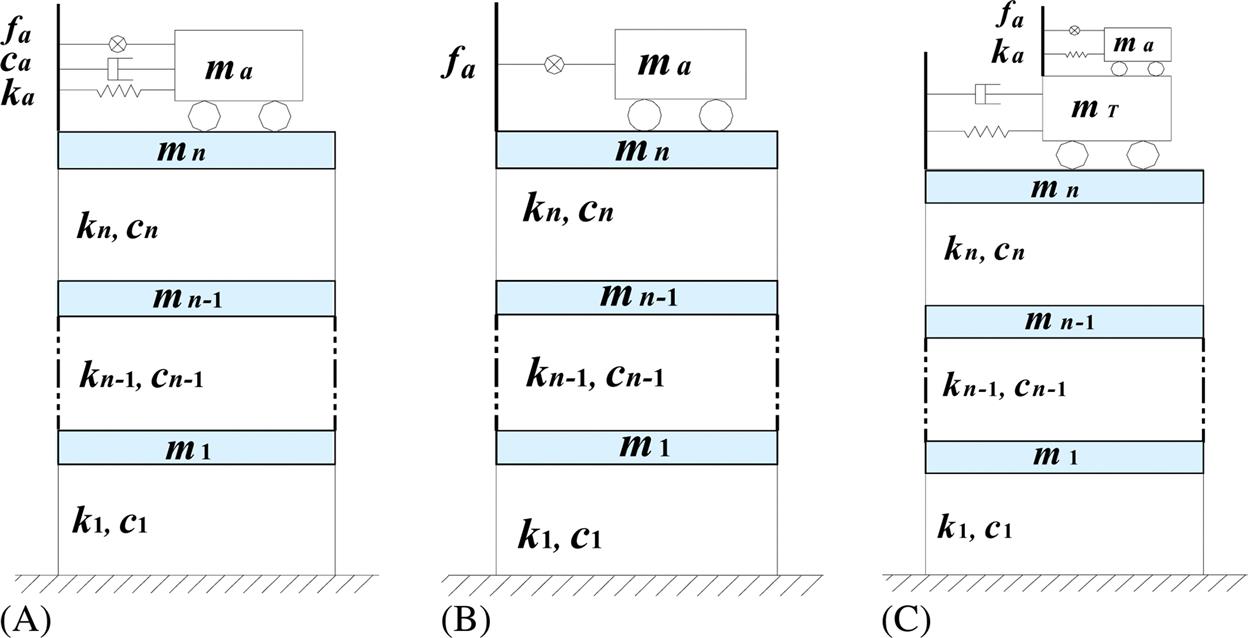
For the standard AMD system, the system is firstly designed as a TMD system without active control actuator. That is to say, under the premise of a given inertial mass, the system should meet the relationships of optimal frequency ratio and optimal damping ratio of a TMD system. Then, based on the designed TMD system, the active control force of the active control actuator is calculated according to the active control algorithm. This design method of the AMD system has two advantages:
1. The AMD system has the reliability of fail-safe: the TMD system will display the passive control effect when the active control actuator fails or stops working.
2. In larger environment disturbance, the active actuator is working while actually the AMD is a system with spring and damper, which has the better control effect and higher control robustness compared to the TMD system. Moreover, when the environmental disturbance is small, the working state changes from AMD to TMD, so the active actuator stop working to save energy and extend the life of the active control actuator.
3.2.2 Construction and Design
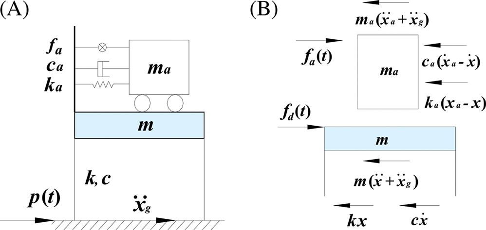
As obviously seen, the construction of a standard AMD system should include four parts, i.e., the inertial mass, the stiffness element, the damping element, and the actuator. Here, the design of a standard AMD system installed on a single freedom structure will be introduced as an example. Fig. 3.3 shows a standard AMD system, the equations of motion of the controlled single-freedom structure can be expressed as
(3.3)
(3.4)
where m, c, and k are the mass, damping coefficient, and stiffness of the structure, respectively. p(t) is the disturbance of the system. ![]() ,
, ![]() , and
, and ![]() separately are the displacement, velocity, and acceleration of structure relative to ground.
separately are the displacement, velocity, and acceleration of structure relative to ground. ![]() is the acceleration of the ground. ma, ca, and ka separately are the mass, damping coefficient, and stiffness of the AMD system.
is the acceleration of the ground. ma, ca, and ka separately are the mass, damping coefficient, and stiffness of the AMD system. ![]() ,
, ![]() , and
, and ![]() separately are the displacement, velocity, and acceleration responses of the AMD system relative to ground. fa(t) are the driving force applied to the inertial mass by the actuator. fd(t) is the active control force provided by the AMD system to the controlled structure, which can be written as:
separately are the displacement, velocity, and acceleration responses of the AMD system relative to ground. fa(t) are the driving force applied to the inertial mass by the actuator. fd(t) is the active control force provided by the AMD system to the controlled structure, which can be written as:
(3.5)
From Eq. (3.3) to Eq. (3.4), the equations of motion of the AMD control system can be rewritten as:
(3.6)
 (3.6)
(3.6)
It can be seen from the right part of Eq. (3.5) that the active control force applied to the structure of the standard AMD system includes the driving force, the damping force, and the elastic force; the stiffness and damping elements of AMD can limit the displacement of inertial mass to some level, and output force is prorated to each device in the vibration process. In addition, the active control force is equal to the inertial force of inertial mass. Therefore the vibration control effect almost depends on the weight of the inertial mass. Generally, it will get the better vibration control effect for taking inertial mass with larger weight.
It can be seen from Eqs. (3.5) and (3.6) that there are four important design parameters for the AMD control system: the driving force, the inertial mass, the damping coefficient, and the stiffness.
As mentioned in Section 3.2.1, there are two steps for designing the AMD control system. In the first step, assuming the active control actuator does not work and the control system can be designed as a TMD system. In the whole system, the structure mass m, stiffness k, and damping coefficient c can be calculated, and the natural frequency of the TMD system is ![]() , the damping ratio is
, the damping ratio is ![]() . Setting
. Setting ![]() is the mass ratio of the AMD system and the structure, then these parameters of the control system ma, ka, and ca can be calculated through Eq. (3.7) [73]:
is the mass ratio of the AMD system and the structure, then these parameters of the control system ma, ka, and ca can be calculated through Eq. (3.7) [73]:
(3.7)
 (3.7)
(3.7)
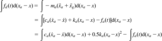
Secondly, the driving force ![]() should be designed according to a particular control algorithm. The two ends of Eq. (3.5) are integrated by
should be designed according to a particular control algorithm. The two ends of Eq. (3.5) are integrated by ![]() , then
, then
(3.8)
 (3.8)
(3.8)
It can be seen from Eq. (3.8) that the work done by the control force applied to the structure is related to the motion of the inertial mass. That is to say, a part of vibration energy of the structure will be converted to the kinetic energy of AMD system. Eventually, the control force applied to the structure will balance the vibration energy to achieve the purpose of structural vibration control. In addition, the work done by the control force is equal to the difference between the external energy and the energy of damping, elastic deformation of AMD system. That is to say, the damping element and the stiffness element of AMD system will consume and absorb a part of vibration energy of AMD system or external energy. Therefore the control effect can be improved by increasing the external energy import.
If there are no stiffness element and damping element in the AMD system, the equations of motion of the AMD control system can be expressed as
(3.9)
In addition, the control force applied on the structure is
(3.10)
Eq. (3.10) shows that when the AMD system has only inertial mass without stiffness element and damping element, the driving force of the AMD actuator equals to the control force, also exactly equals to the inertia force of the inertial mass.
3.2.3 Mathematical Models and Structural Analysis
In the AMD control system, the key point is how to calculate the control force ![]() and make it close to the driving force
and make it close to the driving force ![]() , which involves the control strategy and control device design. The AMD control system is installed on the top of a structure with n degrees of freedom as shown in Fig. 3.4. Here, the
, which involves the control strategy and control device design. The AMD control system is installed on the top of a structure with n degrees of freedom as shown in Fig. 3.4. Here, the ![]() means the earthquake acceleration
means the earthquake acceleration ![]() and the wind load
and the wind load ![]() , the equation of motion of the AMD structural control system can be expressed as
, the equation of motion of the AMD structural control system can be expressed as
(3.11)
where ![]() ,
, ![]() , and
, and ![]() separately are the mass matrix, damping matrix, and stiffness matrix of AMD control system.
separately are the mass matrix, damping matrix, and stiffness matrix of AMD control system. ![]() ,
, ![]() ,
, ![]() separately are the displacement vector, velocity vector, and acceleration vector of the AMD control system.
separately are the displacement vector, velocity vector, and acceleration vector of the AMD control system. ![]() is the position matrix of AMD control force.
is the position matrix of AMD control force. ![]() is the AMD control force vector, which is equal to
is the AMD control force vector, which is equal to ![]() in this model.
in this model. ![]() is the position matrix of the wind-load vector.
is the position matrix of the wind-load vector.

Assuming ![]() , then the state-space equation of the motion of the AMD control system can be expressed as
, then the state-space equation of the motion of the AMD control system can be expressed as
(3.12)
where ![]() ,
, ![]() ,
, ![]() ,
, ![]() .
. ![]() is the measurement matrix,
is the measurement matrix, ![]() is the measurement vector.
is the measurement vector.
In Eqs. (3.11) and (3.12), ![]() actually is the driving force of AMD system, that is to say, structural vibration control can be realized by actively changing the driving force in the design process. Here, taking
actually is the driving force of AMD system, that is to say, structural vibration control can be realized by actively changing the driving force in the design process. Here, taking ![]() to express the driving force
to express the driving force ![]() . The driving force
. The driving force ![]() in Eq. (3.12) can be calculated by any kind of active control algorithm described in Chapter 2, Intelligent Control Strategies. Here, the well-known linear quadratic regulator (LQR) is chosen as the active control algorithm, and the corresponding performance index including response of structure and auxiliary mass is given by
in Eq. (3.12) can be calculated by any kind of active control algorithm described in Chapter 2, Intelligent Control Strategies. Here, the well-known linear quadratic regulator (LQR) is chosen as the active control algorithm, and the corresponding performance index including response of structure and auxiliary mass is given by
(3.13)
where ![]() and
and ![]() separately are the positive semi-definite and positive-definite weight matrices, which are the control parameters in the AMD system design. The optimal driving force, minimizing the performance index based on LQR algorithm is expressed as:
separately are the positive semi-definite and positive-definite weight matrices, which are the control parameters in the AMD system design. The optimal driving force, minimizing the performance index based on LQR algorithm is expressed as:
(3.14)
where ![]() is the gain matrix,
is the gain matrix, ![]() is the positive-definite solution of the following matrix Riccati equation:
is the positive-definite solution of the following matrix Riccati equation:
(3.15)
So, the state-space equation of the AMD control system is transformed to
(3.16)
Eq. (3.16) can be solved by any kind of the numerical methods of solving linear differential equations, such as ![]() method,
method, ![]() method. However, there is a more commonly used method, such as the differential equation solver of function lsim and function ode in MATLAB, to solve the state vector of AMD control system.
method. However, there is a more commonly used method, such as the differential equation solver of function lsim and function ode in MATLAB, to solve the state vector of AMD control system.
Eq. (3.14) can be rewritten as:
(3.17)
where ![]() and
and ![]() are the sub-matrices of the gain matrix
are the sub-matrices of the gain matrix ![]() . Eq. (3.17) shows that the AMD control system applies elastic force and damping force on the structure, that is to say, the AMD control system actually decreases the structural dynamic response by changing the stiffness and damping of the structure. Moreover, a set of AMD device is typically installed on the top of the structure, it can be observed that the AMD control system only changes the nth row elements of the stiffness and the damping matrices by taking Eq. (3.17) into Eq. (3.11).
. Eq. (3.17) shows that the AMD control system applies elastic force and damping force on the structure, that is to say, the AMD control system actually decreases the structural dynamic response by changing the stiffness and damping of the structure. Moreover, a set of AMD device is typically installed on the top of the structure, it can be observed that the AMD control system only changes the nth row elements of the stiffness and the damping matrices by taking Eq. (3.17) into Eq. (3.11).
The design of the AMD control system includes two aspects: one is the design of AMD system parameters, such as inertial mass ma, damping coefficient ca, stiffness ka, and so on, which have been discussed in Section 3.2.2. The other one is AMD control parameter design, such as the maximum driving force and the maximum stroke of inertial mass. These two kinds of parameters are usually coupled, and the latter depends on some particular parameters of the control algorithm (e.g., the weight matrix ![]() and
and ![]() of LQR algorithm).
of LQR algorithm).
The driving force of the AMD control system can be calculated by LQR algorithm, as seen in Eqs. (3.13) and (3.14), and the weight matrix ![]() and
and ![]() greatly influence the driving force, the structural response, and the AMD inertial mass strike. Generally, the greater the
greatly influence the driving force, the structural response, and the AMD inertial mass strike. Generally, the greater the ![]() is, and the smaller the
is, and the smaller the ![]() is, the smaller the structural responses and the greater of driving forces. Moreover, in order to make sure the AMD control system can effectively work, the weight matrix
is, the smaller the structural responses and the greater of driving forces. Moreover, in order to make sure the AMD control system can effectively work, the weight matrix ![]() and
and ![]() should be designed for different disturbance levels, which avoids to be damaged due to large stroke of inertial mass and large driving force under the strong disturbance.
should be designed for different disturbance levels, which avoids to be damaged due to large stroke of inertial mass and large driving force under the strong disturbance.
The purpose of designing the control device is to provide enough driving force to be close to the desired control force. However, the different control devices with different working principle can provide different control effects to the AMD control system. The typical forms of AMD control device are pendulum, rubber pad, rail-type, and so on. Similarly, for these devices of rubber pad and rail-type, equations of motion and control forces which can be obtained from Eq. (3.4) to Eq. (3.5) or from Eq. (3.9) to Eq. (3.10) according to the different working principles.
3.2.4 Experiment and Engineering Example
AMD was proposed to control the structural vibration in 1980 [29]. In the past three decades, more and more experiments and applications of the AMD control system were conducted.
In 1987, Aizawa conducted a shake-table experiment of a four-story model fame installed an AMD, and achieved satisfactory control effect [74]. An active control experiment of AMD system that placed on top of a three-story model steel frame was also conducted by Kobori in 1987 [75]. In the work of Soong in 1988, an AMD was placed on top of a 1:4 scale six-story model steel fame, and the active control experimental results showed the effectiveness of the AMD control system [76]. On the other hand, the first engineering application of the AMD control system in the world was conducted in Japan in 1989 [77], the controlled structure is 11-story office building and the AMD is designed to control the lateral and torsional responses of structure acted by wind load and earthquake. Subsequently, AMD control systems are applied into a lot of high-rise buildings and slender civil structures, especially in Japan.
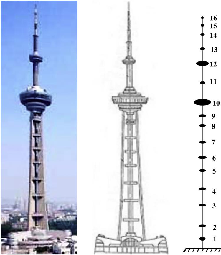
As a typical case of the engineering project, the wind vibration problem of Nanjing TV tower has been solved by using the AMD control system for the first time in China [78–79]. Nanjing TV tower, height 310.1 m, is located in the western suburbs of Nanjing city, the main structure is made up of three prestressed concrete hollow legs with rectangular section as shown in Fig. 3.5. There are two sightseeing platforms located in the tower at the heights of 200 m and 240 m, and the masses of the two platforms are 10000 t and 1000 t, respectively. The analysis results showed that the periods of the tower for the 1st, 2nd, and 3rd mode shape separately are 6.20 s, 2.10 s, and 1.14 s. The bearing capacity and the horizontal displacement of the tower can meet the requirements under the fundamental wind pressure of 0.5 kN/m2 or earthquake intensity of 8 degree. However, the acceleration calculated is 0.2 m/s2 which exceeds the human body comfort level limit 0.15 m/s2. Therefore wind vibration control is needed to conduct to meet the requirement of comfort level. Considering the stiffness above the big platform is far less than the stiffness of the main structure, applying control force on the small platform is a good choice to get a better control effect.
The AMD control system layout of Nanjing TV tower is shown in Fig. 3.6. An electro-hydraulic servo actuator is arranged in the annular site each angle of 120 degree, with the length of 6.5 m, the maximum stroke of 750 mm and the maximum output force of 100 kN. Thus the three driving forces provided by actuators can form two horizontal forces and a torque, so the translation and rotation of TV tower can be controlled successfully. However, the dynamic response of Nanjing TV tower is dominated by the first mode shape, so the AMD system is used to reduce the wind vibration of the first mode shape of the TV tower, and the driving force is calculated according to the LQR control algorithm. The final analysis results are shown in Table 3.1.

Table 3.1
The analysis results of the small turret
| Conditions | Displacement (x/mm) | Acceleration ( | Diving Force (Fa/kN) |
| Uncontrolled | 137 | 31.8 | — |
| AMD control | 89 | 16 | 157.2 |

It can be seen from Table 3.1 that the displacement and acceleration of the small platform are all obviously reduced by using the AMD control system. The controlled result meets the requirement of human body comfort level. So, the AMD control system used in Nanjing TV tower can achieve the desired performance target. Besides, the driving force is not very large, which proves the high efficiency of AMD control system. Recently, Zhou conducted a hybrid mass damper (HMD) control strategy to control the wind-induced vibration of Canton Tower. The HMD consists of two AMD subsystems driven by multiple linear motors with maximum capacity of 18 kN, and some measures are taken to consider the velocity limitation and stroke limitation of AMD. The actual test results show the AMDs can implement the control force synchronously and have a very small time delay which can meet the requirement of vibration control for the Canton Tower [80].
3.3 Active Tendon System
3.3.1 Basic Principles
ATS was proposed by Freyssinet in 1960, which is one of the most widely used active control methods applied in flexible structures, high buildings, and bridges [81]. Active tendon consists of prestressed tendons and actuators, and the prestressed tendons with cross form are always installed between every pair of neighboring floors. The electrohydraulic servomechanism generates the driving force to change the tension of prestressed tendons; as a result, the active control force generated by tendons is applied to the controlled structure. A lot of tests and simulations show the ATS has an excellent control effect on horizontal vibration or torsional vibration of structures.
Actually, the control principle of ATS is similar to AMD, when the structure is subjected to earthquake or wind loads, the structure will deviate from the equilibrium position. Meanwhile, sensors installed on and near the structure measure the information of structural response and external excitation, and transmit signals to the controller. The controller calculates the active control force, according to a particular active control algorithm, and commands the actuator to change the tension of tendons. Finally, some horizontal control forces are applied to the structure, so that the control of structural vibration is achieved effectively.
Besides the excellent control effect, the ATS has some special advantages. Existing tendons can be used or modified as active tendons that few additions or modifications need to be done for an as-built structure, and the additional installation space is unnecessary because of making use of the existing structural members, which is attractive for the efficiency retrofits and strengthening of existing structures [42,81]. On the other hand, active tendon control can accommodate both continuous-time and pulse control algorithms as the ATS can be conducted in the pulsed mode and the continuous-time mode [42,81]. Like other active control mechanisms, ATS has the same drawback that the actuator needs to be supported by a strong external energy, in addition, it is more sensitive to the delay.
3.3.2 Construction and Design
Active tendon consists of prestressed tendons and actuators, the commonly used actuator is electro-hydraulic servo actuator, the prestressed tendon has oblique form and cross form according to the arrangement of the tendon, the widely used ATS in civil engineering is shown in Fig. 3.7.

Fig. 3.7(A) shows the ATS designed by Soong et al. for controlling the structural vibration under seismic loads in 1988, which is also the first generation Benchmark model for structural vibration control [81,82]. Two pairs of diagonal prestressed tendons are installed on the first layer of three-story steel frame, and a connecting frame is used to connect electro-hydraulic servo actuator and the steel frame.
Fig. 3.7(B) shows the ATS designed by Abdel-Rohman for controlling the structural vibration under wind loads in 1983 [30]. The device consists of four prestressed tendons connected to the top corners of the structure, one pass down through pulleys on each side of structure to cover the most flexible region. Four actuators are installed at the certain level to connect the four prestressed tendons, so that the active control can be achieved through tightening or releasing the prestressed tendons.
Fig. 3.7(C) shows the ATS designed by Yang for controlling the structural vibration under wind loads in 1983 [83]. This device combines the features of the above two ATSs, the diagonal prestressed tendons, controllers, and actuators are installed in the space between adjacent floors, the arrangement starts from the top of the structure, and ends in a certain level, ensuring that the most flexible region of structure is controlled.
The determination of the active control force depends on the mathematical model of ATS and the active control algorithm selected. Here, the ATS in Fig. 3.7(C) is chosen as an example to explain the design of active control force, and the stress analysis of a story unit with a pair of prestressed tendons is shown in Fig. 3.8, and the corresponding equation of motion and force-displacement relation are given by
(3.18)
(3.19)
where ![]() ,
, ![]() , and
, and ![]() are, respectively, the mass, damping coefficient, and stiffness of ith story unit.
are, respectively, the mass, damping coefficient, and stiffness of ith story unit. ![]() ,
, ![]() , and
, and ![]() are, respectively, the displacement, velocity, and acceleration of ith story unit relative to the ground.
are, respectively, the displacement, velocity, and acceleration of ith story unit relative to the ground. ![]() is the resultant shear force in all the columns of ith story unit,
is the resultant shear force in all the columns of ith story unit, ![]() is the active control force provided by prestressed tendons of ith story unit.
is the active control force provided by prestressed tendons of ith story unit.

Substituting Eq. (3.19) into Eq. (3.18), the equation of motion of ith story unit can be rewritten as
(3.20)
Considering the force mechanism of every story unit is similar, all the equations of motion are assembled as the equation of the system, and the active control force in the equation of motion can be deleted for the story unit without prestressed tendons. Introducing the boundary conditions of real structure, the equation of motion of the controlled structure with ATS can be written as Eq. (2.1), and ![]() is the control force vector provided by prestressed tendons. In order to use active control algorithm to conduct the active control, the equation of motion of the controlled structure is rewritten as Eq. (2.5).
is the control force vector provided by prestressed tendons. In order to use active control algorithm to conduct the active control, the equation of motion of the controlled structure is rewritten as Eq. (2.5).
Here, the active control force is designed based on pole assignment method described in Section 2.3, and the control algorithm adopts the full-state feedback approach, so the active control force can be expressed as
(3.21)
where ![]() is state feedback gain matrix. Substituting Eq. (3.21) into Eq. (2.5), and the external excitation is ignored, then the state-space equation can be rewritten as
is state feedback gain matrix. Substituting Eq. (3.21) into Eq. (2.5), and the external excitation is ignored, then the state-space equation can be rewritten as
(3.22)
where the gain matrix ![]() is calculated according to the steps described in Section 2.3.
is calculated according to the steps described in Section 2.3. ![]() is designed as
is designed as
(3.23)
The state of the controlled structure is calculated according to the above equations using function ode in MATLAB. However, the control force is just the optimal force applied to the controlled structure in the horizontal direction, not the tension force derived from the prestressed tendons. As the prestressed tendons are arranged in the space between adjacent floors with some certain angles, the force needs to be decomposed according to geometry knowledge. On the other hand, the operation of the actuator that changing the tension force of prestressed tendon is based on the relationship between force and axial deformation of prestressed tendon, so the establishment of the relationship is essential, and the initial prestress of prestressed tendon should also be considered. After the above considerations and operations, the ATS can control the structural vibration in practice.
3.3.3 Experiment and Engineering Example
ATS, as an effective method for structural vibration control, is popular in civil engineering due to easy operation and simple construction, and experiments about ATS were conducted in 1980s. Some control experiments of ATS for some small-scale structural models were performed by Roorda in 1980 [84], the effect of time delay on active control effect was studied, and the problems about the actuator dynamics and placement of sensors were also proposed. From 1986 to 1989, the experiments of ATS were conducted systematically by Soong et al., which consisted of three stages, single-story steel frame, three-story steel frame, and six-story steel frame models, control force is applied by an electrohydraulic servomechanism [85], the experiment results of adopting LQR algorithm and independent modal control were also compared and were both satisfactory. In 2001, the vibration test of cable-stayed bridge model with active piezoelectric tendons was conducted by Bossens and Preumont to demonstrate the control effect of ATS, and a large-scale mockup equipped with hydraulic actuators was tested to demonstrate the practical implementation of ATS [85]. A vibration measurement of a beam with a cable mechanism and the motor was conducted by Nudehi et al. in 2006, the results showed the first two modes of the beam can be effectively controlled [86]. A control experiment on a frame structure with cable actuators was tested by Issa et al. to verify the effectiveness of the control scheme in 2010 [87]. However, ATS requires much more energy and a plurality of actuators that make it difficult to be implemented in an engineering project.
Soong et al. and Takenaka Company in Japan installed an ATS in a full-scale dedicated test structure in Tokyo in 1990, in order to control the structural dynamic response under artificial excitation and actual ground motion [88]. The test structure is a symmetric two-bay, six-story building with the mass of 600 t as shown in Fig. 3.9.

In detail, the structure is a steel frame which is composed mainly of rectangular tube columns, W-shaped beams, and reinforced concrete stab. The fundamental periods in strong direction and weak direction are 1.1 s and 1.5 s, which is the typical case of high-rise building. The active control system consists of digital controller, sensors, hydraulic servo actuators, and braces, and the diagonal braces are installed in the first story of the building, which can expand and contract to control the structural response. The measured stiffness of the braces in x-direction and y-direction are 98.4 KN/mm and 73.8 KN/mm.
The active control algorithm adopted the simplified three-velocity feedback control based on linear optimal control theory, which requires smaller control force, but more power is required. The peak responses of the sixth floor are generally reduced in the x-direction, but less affected in the y-direction, and the root mean square responses are reduced in all cases, which indicates an overall reduction of vibration amplitudes throughout the motion.
3.4 Other Active Control System
Besides the above two main active control systems, some different forms of active control systems are applied in civil engineering, such as an active support system, pulse generator system, and active aerodynamic wind deflector system. The active support system is similar to the ATS, so the related analysis and research are not introduced in the following. The pulse generator system and active aerodynamic wind deflector system will be introduced to display the different working forms of active control systems.
3.4.1 Form and Principles
The pulse generator system is designed to reduce the gradual rhythmic buildup of structural response caused by resonance case [89]. Generally, pulse generator releases air jets to generating short-interval and high-energy pulses, and the magnitude and direction of control pulse depend on the particular control algorithm. Compared to other control systems, it has the advantage of a low-energy input and better real-time operation, and is more effective for critical state control. The pulse generator system usually consists of sensors, controllers, actuators, and pneumatic power supply, Fig. 3.10 shows a pulse generator system designed by Miller in 1988 [89]. The actuator consists of two commercially available solenoids, and the compressed air flow through the nozzle to generate the control pulse. When the structure is subjected to external excitation, the sensors collect the information of structural responses. Once the thresholds at some specified positions are exceeded, the generator will be triggered to generate control pulses. The amplitude of the pulse depends on control algorithm which minimizes the defined cost function; in addition, the direction of control pulse can also be adjusted to achieve a more effective control effect.

Active aerodynamic wind deflector system suppresses wind-induced vibration of the structure by changing the area of windshield to adjust the suffered wind pressure, which meets the requirements of structural safety and human comfort. Obviously, the aerodynamic control needs less energy supply since the active control force is derived from wind power, so the distinct disadvantage is that the control system only controls the vibration induced by wind. Active aerodynamic wind deflector system consists of sensors, controllers, actuators, and appendages (or windshield). Klein designed a simple aerodynamic appendage that reduces wind-induced vibration of tall building, as shown in Fig. 3.11 [90]. Fig. 3.12 shows an aerodynamic flap system designed by Gupta and Soong in 2000 [91]. The working principle of active aerodynamic wind deflector system is similar to the other active control system, but the generation of the control force is special. The actuator adjusts the area and the direction of appendages (or windshield) to exploit the wind power, the suffered wind pressure on the appendages (or windshield) as the control force is applied to the controlled structures.


3.4.2 Analysis and Tests
For the structure controlled by the pulse generator system, the rhythm buildup of structural responses can be destroyed by the control pulse with suitable magnitude and direction. So, the magnitude and direction of control pulse are the main parameters of the control system. Assuming the structure is subjected to earthquake excitation, the generators are distributed through the controlled structure that the direction of control pulse is determined. When some specified thresholds are exceeded, the pulse generator will be activated, and the optimal control pulse is determined that keeps the cost function minimal over a relatively short time segment Topt. The structural response can be assumed that the stochastic component is superimposed on deterministic component, and the purpose of the control is to minimize the deterministic component, the control pulse vector can be expressed as
(3.24)
where ![]() is the amplitude vector of control pulse,
is the amplitude vector of control pulse, ![]() is an arbitrary time history. Neglecting the mean value of the earthquake excitation during the period t0 to T0 = (t0 + Topt), the structural responses are given by solving the following equation of motion
is an arbitrary time history. Neglecting the mean value of the earthquake excitation during the period t0 to T0 = (t0 + Topt), the structural responses are given by solving the following equation of motion
(3.25)
Considering the initial conditions and applying the modal approach, the final structural responses can be written as
(3.26)
where the matrices are related to the time, and the meaning and the elements in the matrices are mentioned in reference [89]. Because the earthquake excitation is regarded as zero-mean random process in Topt, the structural responses do not depend on the earthquake excitation, the variance of displacement responses can be expressed as
(3.27)
The final control pulses are determined by selecting the appropriate cost function, the kinetic energy of the controlled structure is selected as the cost function
(3.28)
It is worth noting that the above approaches are based on the linear model, the nonlinear characteristic of structure is not considered. The solution based on modal approach is not applicable to solve the nonlinear problem of control pulse, but a very simple and reliable method for nonlinear structure to determine the optimal control pulse is presented by Masri [92].
For the active aerodynamic wind deflector system, the area of the windshield is the main parameter. Here, the active aerodynamic bidirectional system designed by Gupta is used to explain the determination of the area of flaps and angular amplitude of rotation, which is shown in Fig. 3.13.

The system consists of two flaps (or appendages) which rotates about the leading edge of the controlled structure, the exposed area of flaps suffers wind pressure to produce drag forces, so the along-wind motion of structure is controlled. The equation of along-wind motion of structure can be expressed as:
(3.29)
where AP(t) is the exposed area of flaps, which is a function of time, S is the control switching function which guides the flap operation, and the meanings of the above symbols are explained in the reference [91]. On the other hand, the system also works as the vertex generator to produce the vortices with the optimal frequency and phase. This feature can be exploited to reduce the potentially hazardous vibration caused by the resonance case, so the across-wind motion of the structure is also controlled. The equation of across-wind motion of structure can be expressed as:
(3.30)
where v(t) is the actuator feedback and the influence of the system on the across-wind motion of the structure, the meanings of the other symbols are also explained in Ref. [91]. In addition, the switch function introduces bidirectional coupling in the two vibratory directions through the control term. The control approach in the across-wind motion is derived from the dissipative effects of parameters, and the control algorithm belongs to the closed-loop feedback algorithm, the above v(t) is the feedback of wake, and the feedback proposed by Fujino et al. [93] can be adopted. The switch function proposed by Klein et al. [90] can be adopted to control the along-wind motion of the structure, and the direction of the sway of controlled structure determines the working condition of the switch function. For bidirectional control of structure, a modified switching function is proposed to achieve a satisfactory control effect [91].
Traina et al. conducted a pulse control on the six-story frame using pneumatic, hydraulic, and electromagnetic actuators, and the experimental results demonstrated the feasibility, reliability, and robustness of the pulse control [94]. Soong and Skinner conducted a wind tunnel experiment on a 1:400 scale elastic model installed aerodynamic appendages, and the result showed a significant reduction in the structural responses [81]. Gupta also conducted a wind tunnel experiment on a rigid model and a flexible model installed active aerodynamic control device, the results showed that the across-wind motion can be controlled effectively, and the assumptions in the mathematical model were also verified [91]. Kobayashi conducted a wind tunnel experiment on the sectional model of a bridge with the control wings, these wings provide aerodynamic forces with adequate phase and amplitude, the test results showed the flutter speed was increased by a factor of two [95]. Nissen adopted an active aerodynamic appendage system to control the wind-induced oscillation in long suspension bridges, the analysis showed that the critical wind speed for flutter instability and the divergence was increased by the active control [96].