ISP Service Pricing, Service-Level Agreements, and Technical Characteristics
In addition to evaluating the availability of services, customers should consider pricing and technical characteristics of an offered service before selecting a service provider. Although technical characteristics in particular might seem intimidating, they have enormous implications for the reliability and ease of use of the provider that you eventually select. Technical issues that this section addresses include backbone characteristics, circuit demarcation, and dedicated hosting.
ISP Service Pricing
Prices for services can vary dramatically between ISPs, even for the same services and within the same geographical regions. The provider's relative strength and amount of investment in a particular area often determine the price of a given service. For example, a provider that has established Frame Relay service will probably give you a much better price than a provider that has just begun deploying Frame Relay service. On the other hand, the new provider might be more competitive because it doesn't have an investment in legacy infrastructure required to accommodate the service and can take advantage of new platform densities and provided service capabilities.
Because of this and many other factors, getting the same price from different providers does not necessarily mean you're getting the same services. For example, with dedicated access, some providers include the CPE (discussed in more detail later in this chapter), such as a router and CSU/DSU (Channel Service Unit/Data Service Unit), as part of the product. Others charge you an extra fee for the CPE, or require that you arrange for it yourself, which can make the bottom line substantially different. You might find that you'll save a significant amount of money if you supply CPE yourself, or perhaps it might be more appealing for you to pay the provider to supply and/or manage the CPE.
Large companies often purchase national and international Internet and other communications services from a single provider. A bundled solution from a single provider usually means better control and coordination of services between the different regions of the same network. Some providers offer consolidated billing plans for all their services, national and international, and often provide significant discounts to clients who purchase multiple services, such as long distance and Internet access. This bill consolidation means one invoice and one check, which is considered a plus for many companies. Of course, if the convenience of consolidated billing or common services is not an important issue, companies might find better deals for national and international services from different service providers.
Service-Level Agreements
Many service providers today are also creating very competitive SLA/SLGs (Service-Level Agreements/Service-Level Guarantees) that define a basis for guaranteed performance and availability when using their services. Ensure that the details of these agreements, as well as penalties for failure to comply, are clearly defined. Also, ask the provider how the guarantees are currently monitored and whether exception reports (failure to comply with the guaranteed level of service) are automatically generated and followed through on, or whether notifying the provider of exceptions is the customer's responsibility.
These guarantees usually address acceptable percentages of packet loss and delay incurred on their network, as well as access circuit availability and maintenance and/or outage notification time lines.
Commitments a service provider makes in SLAs can be a true service differentiator; however, identifying violations and collecting penalties might prove quite challenging.
ISP Backbone Selection Criteria
An ISP's backbone network encompasses many important technical characteristics, including the following:
-
Physical network topology
-
Network bottlenecks and subscription ratios
-
Level of network and individual network element redundancy
-
Interconnections with other networks, including distance to destinations and traffic exchange agreements
This section is aimed at both customers and designers of ISP networks. Customers should certainly evaluate these characteristics when choosing a provider; they are far more important than pricing when attempting to predict service quality. Architects should consider the potential benefits and pitfalls associated with these characteristics when setting up or expanding their networks.
Physical Connections
Customers should investigate the provider's physical network topology, and the provider should be able to provide a recent map of the network with every connection indicated. With respect to connections, a healthy physical topology is one that can provide consistent, adequate bandwidth for the entire traffic trajectory, even in the event that single or multiple connections become unavailable. The existence of high-speed backbone links such as OC12 and OC48 does not by itself guarantee high-speed access for the customers. Your traffic might enter the provider's network from a low-speed backbone connection, or a high-speed but severely oversubscribed backbone connection. These are all things that will affect the quality of your connection.
Potential ISP Bottlenecks and Subscription Ratios
The provider's network is only as strong as its weakest link. There are two potential ISP bottlenecks: oversubscription of backbone trunks and small tail circuits leading to a POP or downstream customer. A provider should not recklessly oversubscribe its connections. ISPs that attempt to save money by overloading their routers or connections will end up losing credibility in the long run.
Oversubscription occurs when the cumulative utilization of multiple links exceeds the bandwidth of the pipe used to carry the traffic to its destination. A provider selling 20 T1s at a POP and connecting to a NAP via a T1 link will experience a bottleneck at the NAP connection. As illustrated in Figure 2-3, a common rule of thumb is a 5:1 ratio—there should be no more than five T1 links for each T1 backbone connection. Subscription ratios vary based on the product being offered. Typically, dedicated hosting providers often use 8:1 or even 10:1 ratios. These values are usually based on past experiences and projected utilization, but if they are not carefully selected and managed, they can quickly result in congestion.
Figure 2-3. An ISP's Weakest Link Limits Performance

Another example of a potential bottleneck is high-speed sites trying to access information from low-speed sites. A Web server located at a site connected to the Internet via a 56 kbps link can be accessed at a maximum aggregate speed of only 56 kbps, regardless of the speed of the links used by the persons accessing the site. Figure 2-4 illustrates a client with T3 access to the Internet that will be limited to no more than 56 kbps when accessing the Web server. Also note that if other users are attempting to access the site at the same time, everyone must share the 56 kbps connections.
Figure 2-4. Access Speed Is Limited by the Smallest Bandwidth

It's important that providers monitor and manage link utilization in their networks. Before committing to purchasing services from an ISP, customers should ask potential providers the following questions:
-
How do you manage link utilization?
-
At what thresholds do you begin to provision additional capacity?
-
What are typical subscription ratios (available capacity:utilized capacity) for this service?
-
What are typical subscription ratios for your backbone network and interconnection points?
-
What is the theoretical bottleneck for this service?
Level of ISP Internet Access Redundancy
Murphy is out there, ready to make your life miserable. Whether because of bad weather, carrier problems, or just plain bad luck, an ISP's connection to a NAP, another provider, or another POP will become unavailable at some point, potentially resulting in the inability to reach all or a set of destinations. A redundant network enables traffic to utilize an alternative path to reach those destinations until the problem has been corrected. A well-designed ISP network has POPs connected to multiple NAPs, other provider networks, and multiple other POPs, as illustrated in Figure 2-5.
Figure 2-5. A Redundant Network Provides More Reliable Connectivity
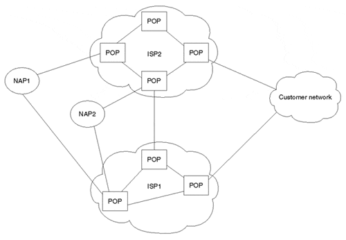
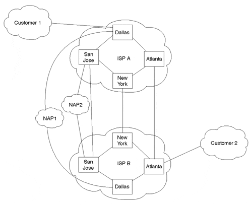
It's important to understand that peering and interconnection redundancy to other networks are usually provided on a global basis. In other words, if a connection to a provider becomes unavailable via the primary traffic exchange point, the next closest exchange point will be selected. The idea behind this is to not provision redundant capacity from the same location to another network, but to ensure that enough spare interconnection and backbone capacity exists to accommodate failures in one (or more) locations in the network. With this approach, provisioning more interconnection and NAP circuits in more geographically optimal locations can offset costs of the redundant connections, benefiting the network during both normal operation and failure scenarios by providing this redundancy on a global versus POP-by-POP basis. Figure 2-6 illustrates a less-than-optimal connectivity model, and 2-7 illustrates a redundant interconnection model.
Figure 2-6. Less-Than-Optimal Connectivity Model

Figure 2-7. Redundant Interconnection Model
A provider's sparing plan should also be considered when discussing redundancy. Most providers keep an on-site supply of critical hardware components and manage spare equipment as a ratio of working:spare. The number of spare components usually depends on the critical nature of the component, as well as the component's theoretical 4848MTBF (Mean Time Between Failures).
Some providers choose to outsource the sparing services, normally to vendors who maintain geographically dispersed depots and share the inventory among several customers. Although this approach does potentially increase MTTR (Mean Time To Repair) when problems occur—and sometimes results in availability constraints of popular components—it's certainly better than no sparing plan at all.
Distance to Destinations
A typical misconception is that customers should be concerned only with the number of IP hops—that is, the number of IP routers—required to reach a given destination network through their ISP. In the past, it was somewhat true that more IP hops tended to introduce more potential for packets to be delayed, misdirected, or garbled. Today, however, many ISP backbone networks are based on MPLS (Multiprotocol Label Switching), ATM, or Frame Relay technologies, which result in many device hops at Layer 2 but are transparent to IP path-detection tools such as traceroute.
A smaller number of IP hops to a destination via a given network may very well indicate a better path to the destination than via a network with more IP hops. However, understanding what technologies intermediate networks are based upon is important before making any such assumptions. For example, it might be more desirable to take several through high-speed links than to travel over a single low-speed link.
As you know by now, the Internet is a conglomeration of overlapping backbone networks connected via exchange points and direct interconnections. Evaluating the number of network or AS hops (the number of routing domains traversed) to a given set of destinations is a reasonably good idea. The distance to destinations will depend on how many destination networks purchase connectivity from the provider and how well the provider is connected to other networks. Smaller providers might connect to only one NAP, or they might not connect to any NAPs at all. Larger providers often connect to other networks via both the NAPs and direct interconnections.
Traffic Exchange Agreements
It's an absolute requirement that ISPs be part of traffic exchange agreements, which are usually negotiated bilaterally on a peer-by-peer basis. Given the architecture of the Internet today and the little regulation governing who should interconnect how (directly or at which NAPs), it's entirely up to ISPs how to approach the traffic exchange model.
For years, ISPs have tossed around ideas regarding settlements associated with interconnecting networks, but arguments about who pays whom and how the costs should be measured have produced little consensus. As discussed in Chapter 1, "Evolution of the Internet," larger ISPs are beginning to move more and more traffic to a more distributed direct interconnection model, utilizing NAPs only to connect to smaller providers. Larger ISPs are also becoming much more strict regarding whom they'll peer with at the NAPs. That information is often protected by a mutual NDA (Nondisclosure Agreement) executed between both parties.
Although potential providers likely won't be very keen about the idea of releasing specifics of traffic exchange agreements with other networks, they usually are willing to provide aggregate available capacity numbers and other useful information regarding interconnections and peering policies. How a provider connects to other networks could be the single most important piece of information regarding potential throughput characteristics of a connection you purchase.
Demarcation Point
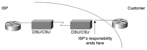
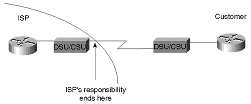
Finally, in addition to pricing, backbone, and interconnection issues, customers should consider demarcation point (DP) issues when selecting an ISP and executing an agreement. A demarcation point is the point that differentiates the provider's network and responsibilities from the customer's network and responsibilities. This is particularly true in a service provider's dedicated hosting environment. It is important to understand the difference between the responsibilities of the provider and those of the customer. Demarcation points are defined down to the cables and connectors to make sure that no disagreements occur in case of equipment or network problems. Figure 2-8 illustrates a typical demarcation point between an ISP network and a customer network.
Figure 2-8. Demarcation Point

Different providers define the demarcation point differently, usually depending on who is paying for the equipment and access line, where the equipment is located, and who manages it.
Customer Premises Equipment
Customer premises equipment (CPE) usually includes the router, the CSU/DSU, the cabling, and often an analog modem for OOB (out-of-band) access for monitoring and management. ISPs typically offer the customer a choice of buying the CPE and access line, buying just the access line, or just paying a monthly fee with all equipment and access needs taken care of by the ISP. As with most everything, any arrangement is available at the right price. ISPs usually are responsible for maintaining equipment or packages that they provide. ISPs usually have predefined packages that include the CPE and/or access. If the customer does not want to take the package, he would be required to choose equipment that has been preapproved by the ISP. The customer would then be responsible for troubleshooting and maintaining his own equipment. The provider is always available to solve problems, usually for an extra fee. Figures 2-9 through 2-11 illustrate some examples of ISP packages.
In the scenario illustrated in Figure 2-9, the ISP is responsible for the access line and the CSU/DSU all the way up to the CSU's serial connector at the customer location. Restrictions might be imposed on the customer premises router to meet some memory or software revision guidelines.
Figure 2-9. Example: ISP Provides Access and CSU/DSU; Customer Provides Router
In the scenario illustrated in Figure 2-10, the ISP has provided everything, and its responsibility ends at the LAN port on the router at the customer's premises.
Figure 2-10. Example: ISP Provides Access, Router, and CSU/DSU

In the scenario illustrated in Figure 2-11, the customer provides the CPE and the access line. The provider's responsibility ends at the POP's wiring closet, where the ISP interconnects with the carrier's central office.
Figure 2-11. Example: Customer Provides Everything
Router Collocation
Collocation is the act of placing one party's equipment on another party's premises. An example of collocation is putting the customer's router at the provider's site or hosting center, as illustrated in Figure 2-12. The customer motivations for such a collocation scheme would be to have the ISP provide faster access speeds or local monitoring of the equipment, or perhaps to give the customer better control of access bandwidth utilization.
Figure 2-12. Collocation Example: Customer Router Located at ISP Site

The opposite of the situation described in Figure 2-12 is for the ISP to collocate its own POP router at the customer's site, as illustrated in Figure 2-13. Usually in this case, the ISP would purchase the access line and the router and would charge the customer a fee for the entire service.
Figure 2-13. Collocation Example: ISP Router Located at Customer Site

