
In the first project of this chapter, we are going to learn how to control all the modules we assembled before from a cloud dashboard, using the aREST framework we already used in this book.
First, let's configure all the modules. We are going to start with the LED dimmer module, which is the easiest to configure. Here is the complete code for this module:
// Import required libraries
#include "ESP8266WiFi.h"
#include <PubSubClient.h>
#include <aREST.h>

// Clients
WiFiClient espClient;
PubSubClient client(espClient);

// Unique ID to identify the device for cloud.arest.io
char* device_id = "6g37g4";

// Create aREST instance
aREST rest = aREST(client);

// WiFi parameters
const char* ssid = "wifi-name";
const char* password = "wifi-pass";

// The port to listen for incoming TCP connections
#define LISTEN_PORT           80

// Create an instance of the server
WiFiServer server(LISTEN_PORT);

void setup(void)
{
  // Start Serial
  Serial.begin(115200);

  // Set callback
  client.setCallback(callback);

  // Give name and ID to device
  rest.set_id(device_id);
  rest.set_name("dimmer");

  // Connect to WiFi
  WiFi.begin(ssid, password);
  while (WiFi.status() != WL_CONNECTED) {
    delay(500);
    Serial.print(".");
  }
  Serial.println("");
  Serial.println("WiFi connected");

  // Start the server
  server.begin();
  Serial.println("Server started");

  // Print the IP address
  Serial.println(WiFi.localIP());

}

void loop() {

  // Handle REST calls
  rest.handle(client);

}

// Handles message arrived on subscribed topic(s)
void callback(char* topic, byte* payload, unsigned int length) {

  // Handle
  rest.handle_callback(client, topic, payload, length);

}
There are several things you need to modify in this code. You need to substitute the Wi-Fi name and password for your own. You also need to modify the device ID of the device, so it has a unique identifier on the network. Finally, you can also modify the name of the device, for example to add some data about where the module is located in your home.
Once that's all done, upload the code to the board, and then move on to the next device: the motion sensor.
For this module, the code is nearly the same, we just need to add some lines to constantly measure the state of the motion sensor and make it available on the cloud. For that, we first define a variable that will host the motion sensor state:
int motion;
Then, we expose this variable to aREST:
rest.variable("motion", &motion);Next, inside the loop() function of the sketch, we simply measure the state of the motion sensor:
motion = digitalRead(5);
After modifying the same parameters as for the LED module (Wi-Fi credentials, device ID, and name), upload the code to the board.
Finally, let's deal with the sensor module. For this one, you will need to import the DHT library:
#include "DHT.h"
Then, you will need to define which pin the sensor is connected to:
#define DHTPIN 5
#define DHTTYPE DHT11
After that, create an instance of the sensor:
DHT dht(DHTPIN, DHTTYPE, 15);
We also create two variables that will hold the value of the measured temperature and humidity:
float temperature;
float humidity;
In the setup() function of the sketch, we initialize the DHT sensor:
dht.begin();
We also expose those variables to the aREST API:
rest.variable("temperature",&temperature);
rest.variable("humidity",&humidity);
Finally, inside the loop() function of the sketch, we measure the temperature and humidity of the sensor:
humidity = dht.readHumidity();
temperature = dht.readTemperature();
Again, modify the required parameters inside the sketch and upload it to the board. Note that to power all the modules, you can, for example, use either an external battery or a breadboard power supply; you do not need to have one FTDI cable per module.
It's now time to control all our boards from the cloud! First, go over to the aREST dashboard website:
Create a new dashboard for your home automation system:

Inside this dashboard, switch to edit mode and add the first element that will hold the temperature measurement. Make sure to enter the correct ID of your temperature and humidity module:
Next, do the same for humidity, and you should get the following result:

We are now going to add the LED dimmer module. As we want to be able to control the intensity of the LED light, create a new element with the Analog option:
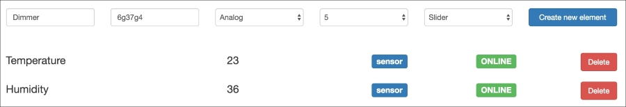
You should now be able to control the intensity of the LED via a slider inside the dashboard:

Finally, create a new element for the motion sensor:

You should end up with a dashboard that has all the elements of the simple home automation system we just built:

Congratulations, you just built a complete home automation system based on the ESP8266, which you can now control from the cloud. You can of course add more modules to the system, and control them from the same dashboard.
We are now going to build another project based on the same hardware we have already built in this chapter. This time, we are going to make an alarm system based in the cloud, using the ESP8266 module along with the PIR motion sensor.
I will show you how to do it with just one PIR sensor, but you can of course add more modules that will be dispersed around your home or any building you wish to monitor. To do that, we are going to again use IFTTT, which will send you a text message every time motion is detected by any of the motion sensor modules.
Let's first see how to configure a given module. As it's code that is very similar to what we already saw earlier in this book, I will only highlight the most important parts here.
You need to set the key that is linked to your Maker channel on IFTTT:
const char* host = "maker.ifttt.com";
const char* eventName   = "motion_detected";
const char* key = "key";
Then, inside the loop() function of the sketch, we read the status of the motion sensor:
bool motion = digitalRead(5);
We then check whether any motion was detected:
if (motion) {If that is the case, we build a request that we will send to IFTTT:
String url = "/trigger/";
    url += eventName;
    url += "/with/key/";
    url += key;
We then actually send this request to the IFTTT servers:
client.print(String("GET ") + url + " HTTP/1.1
" +
                 "Host: " + host + "
" +
                 "Connection: close

");
    int timeout = millis() + 5000;
    while (client.available() == 0) {
      if (timeout - millis() < 0) {
        Serial.println(">>> Client Timeout !");
        client.stop();
        return;
      }
    }
After that, we read the answer:
while(client.available()){
    String line = client.readStringUntil('
');
    Serial.print(line);
 }
We then wait for a long time before sending new alerts; otherwise we'll just send a lot of messages to your mobile phone:
delay(10 * 60 * 1000);
Now, grab the code (for example from the GitHub repository for the book), modify it with your own credentials, and upload it to the board.
Now, head over to IFTTT to create a new recipe:
As the trigger channel, select the Maker channel:

As the event, insert motion_detected, which is also what we put in the code:

As the action channel, we'll select SMS here, as it will be the fastest way to contact you in case an alarm is triggered by your motion sensor:

You can insert whatever you wish as the message, for example:

Now, create the recipe and activate it. You should see that whenever you pass your hand in front of the sensor, it will almost immediately send an alert message to your phone. If you wish to stop your alarm system, it's then as simple as deactivating the recipe on IFTTT.
You can of course add more sensors to the system, making each publish the same alert on IFTTT. Therefore, whenever any sensor detects motion, you will receive an alert on your phone.
In the last part of this chapter, we are going to play a bit more with IFTTT. This time, instead of using the motion sensor, we'll see how to use the different trigger channels of IFTTT to create nice automation flows to control the LED module. Of course, remember that you could replace the LED with any appliance you wish to control, for example a lamp.
The Maker channel of IFTTT can also be used as an action channel, and this is what we are going to use here. We will use it to call the aREST API whenever a given condition is triggered.
We are first going to configure the module again, so it can receive commands from the cloud. This is the part of the code before the setup() function:
// Import required libraries
#include "ESP8266WiFi.h"
#include <PubSubClient.h>
#include <aREST.h>

// Clients
WiFiClient espClient;
PubSubClient client(espClient);

// Unique ID to identify the device for cloud.arest.io
char* device_id = "6g37g4";

// Create aREST instance
aREST rest = aREST(client);

// WiFi parameters
const char* ssid = "wifi-name";
const char* password = "wifi-pass";

// The port to listen for incoming TCP connections
#define LISTEN_PORT           80

// Create an instance of the server
WiFiServer server(LISTEN_PORT);
This is the setup() function of the code:
void setup(void)
{
  // Start Serial
  Serial.begin(115200);

  // Set callback
  client.setCallback(callback);

  // Give name and ID to device
  rest.set_id(device_id);
  rest.set_name("dimmer");

  // Connect to WiFi
  WiFi.begin(ssid, password);
  while (WiFi.status() != WL_CONNECTED) {
    delay(500);
    Serial.print(".");
  }
  Serial.println("");
  Serial.println("WiFi connected");

  // Start the server
  server.begin();
  Serial.println("Server started");

  // Print the IP address
  Serial.println(WiFi.localIP());

  // LED pin to output
  pinMode(5, OUTPUT);

}
Finally, here is the loop() function of the code:
void loop() {

  // Handle REST calls
  rest.handle(client);

}

// Handles message arrived on subscribed topic(s)
void callback(char* topic, byte* payload, unsigned int length) {

  // Handle
  rest.handle_callback(client, topic, payload, length);

}
Now, modify the important credentials (Wi-Fi name and password, and device ID) in the code, and upload it to the board.
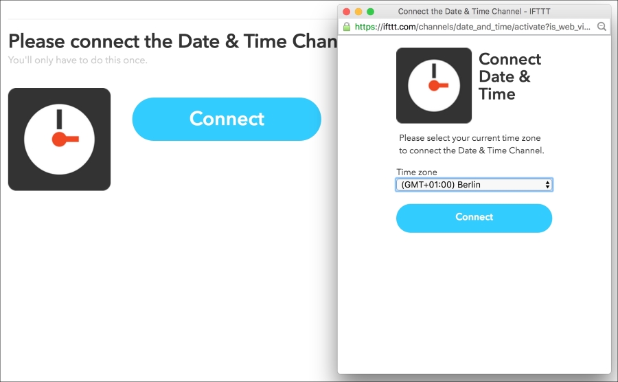
Then, go back to IFTTT. The first thing we are going to do is to make a project to light up the LED at a given time (for example, when it's becoming dark outside), and then it off again at another time (for example, when you go to bed).
For that, create a new recipe with Date & Time as the channel. You might need to connect it first if you have never used it before:
For the trigger type, select Every day, and enter the time at which you want the LED to turn on.
Then, for the action channel in IFTTT, select the Maker channel, and then select Make a web request. This will allow IFTTT to send a command to the aREST.io cloud server.
As the request, enter the following parameters, of course changing the device ID with the one you used inside the sketch:

Now, do the same with the time you want the LED to turn off, for example at 11.30 PM:

Choose the same action channel as earlier:

For the web request, enter the same parameters as before, but this time with the command to switch pin number 5 to LOW:

Now, validate the recipe:

It's now time to see the recipe in action! Make sure the ESP8266 board is correctly configured, and also that the recipes are activated in IFTTT. Whenever the time conditions are met, you should immediately see the LED turn on or off. You can, of course, modify the times inside the recipes to test them.
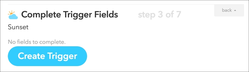
Now, let's play with another trigger channel to see how powerful IFTTT is. You can, for example, use the Weather channel to check whether it's sunset, to automatically turn on the LED at this time without having to enter a fixed time.
To do so, create a new recipe and select the Weather channel, which you need to connect to:

To connect the Weather channel, you simply need to enter your current location:

As the trigger type, I chose to trigger the even at sunset:
As the action channel, I selected the Maker channel, as I did earlier:

Also, just as in the previous recipe, I decided to turn the LED on whenever the recipe is triggered:

You can now see the newly created recipe:

You should now see that whenever sunset approaches, the LED will automatically turn on. You can of course play with more conditions inside IFTTT, and even use the Maker channel as both the trigger and the action channel, to link the different modules of your home automation system via IFTTT.
In this chapter, we built the different components of a home automation system based on the ESP8266, and we saw how to control everything from the cloud. We first created a cloud dashboard to control all the devices from a single interface. Next, we used IFTTT again to create an alarm system that automatically sends you alerts on your phone whenever motion is detected. The easiest way to build your own system based on this project is to simply add more modules, so it suits the needs you have in your own home. For example, it is really easy to add several motion sensor modules so you can have a complete alarm system deployed in your home, and that you can manage using a simple web browser.
In the next chapter, we are going to use the ESP8266 for a completely different application: building a mobile robot that we will control from the cloud.